Comparative Study of Longitudinal Shear Design
Criteria for Composite Slabs
Estudo Comparativo dos Critérios de Dimensionamento
ao Cisalhamento Longitudinal em Lajes Mistas de Aço
e Concreto
J. M. CaLixto a [email protected]
G. BrenDoLan b té[email protected]
r. PiMenta c [email protected]
© 2009 IBRACON
a Structural Engineering Department, College of Engineering, Federal University of Minas Gerais, [email protected], Av. do Contorno 842
- 2º andar, 30110-060 - Belo Horizonte, MG, Brazil.
b METFORM S. A., té[email protected], Av. Roberto Bertoletti 851– 12040-470 - Taubaté, SP, Brazil. c CODEME S. A., [email protected], BR 381 – Km 421– 32530-000 - Betim, MG, Brazil.
Received 8 January 2009; Accepted 16 March 2009; Published 26 June 2009
abstract
resumo
ABNT NBR 8800 (2008) prescribes two longitudinal shear design criteria for composite slabs with ribbed decking: m-k method and par-tial interaction method. The m-k method is considered the worldwide standard method. In this method, the longitudinal resistant shear strength is obtained from linear regression of test results. The partial composite method is an alternative to the m-k method and shall be used only for composite slabs with a ductile behavior. In this scenario, the objective of this paper is to compare these two methods with respect to test results of full size composite slabs employing steel-deck MF 50 manufactured by METFORM. The analysis of the comparative study shows good correlation between the two methods with respect to the prediction of the ultimate strength of the tested composite slabs.
Keywords: composite slabs, ribbed decking, longitudinal shear.
A ABNT NBR 8800 (2008) permite dois critérios para avaliação da força cortante longitudinal resistente última em lajes mistas de aço e concreto: método m-k e método da interação parcial. O método m-k é o método considerado internacionalmente como padrão para o cálculo dessa força cortante longitudinal resistente. Neste método, a resistência das lajes é obtida por regressão linear dos resultados de ensaios realizados com fôrma de uma mesma espessura. O método da interação parcial, por outro lado, surge como alternativa ao método m-k, para melhor explorar o
comportamento dúctil dos peris de fôrma de aço disponíveis no mercado, os projetos de mossas mais bem elaborados e a utilização de vãos
maiores. Dentro deste cenário, o objetivo deste trabalho é fazer uma análise comparativa entre estes dois critérios. Para atingir este objetivo, lajes
mistas, em escala natural e com diferentes dimensões de vãos e altura total, foram construídas e testadas, na condição de simplesmente apoia -das. A fôrma de aço incorporada utilizada foi o steel-deck MF 50 fabricado pela METFORM. A análise dos resultados revela valores similares da força cortante longitudinal resistente última entre os dois critérios para a fôrma de aço incorporada utilizada.
1. introduction
ABNT NBR 8800 (2008) prescribes two longitudinal shear design criteria for composite slabs with ribbed decking: m-k method and partial inter-action method. The method m-k is considered worldwide the standard method for the calculation of the longitudinal resistant shear force. In this method, this longitudinal shear force in composite slabs is calculated by a semi-empiric equation, which relates the nominal shear strength with the experimental parameters obtained from tests performed on decks of the same thickness. The partial interaction method was developed as an alternative to the method m-k for ribbed decks with a ductile behavior and/or with better-designed embossments and slabs with larger spans. Although more laborious than the method m-k, the partial interaction method also allows the inclusion of reinforcing bars in the positive bend-ing moment regions as well as the contribution of shear connectors lo-cated on the girders supporting the composite slabs.
Based on this scenario, the objective of this paper is to present a comparative analysis between these two design criteria. To reach this objective, full size simple supported composite slabs with dif-ferent total heights and spans were built and tested at Federal Uni-versity of Minas Gerais (Brendolan, 2007). The employed ribbed decking was steel-deck MF 50 manufactured by METFORM. It is worth mentioning that similar studies to the one presented herein
were done by Lopes and Simões (2008) and Calixto et al. (1998).
2. evaluation Methods for
the Longitudinal Shear Strength
2.1 The m-k Method
In this paper, it is used the expression prescribed by ABNT NBR 8800 (2008) given by equation 1.
where:
VRis the longitudinal shear strength force, in N, corresponded to a composite slab width of 1000 mm;
b is the composite slab width, set equal to 1000 mm;
f
d
is the distance, in mm, between the centroidal axis of theproiled steel sheeting and the extreme iber of the composite slab
in compression;
A
F,fe is the effective cross-sectional area of proiled steel sheeting,in mm2, corresponded to a width of 1000 mm;
s
L
is the shear span, in mm; andm andk are empirical factors, derived from tests, for design shear resistance.
The method consists in rewriting equation 1 in the form
k
X
m
Y
=
⋅
+
, where and . Inthis last relation, Vut is the longitudinal resistant shear force, per meter of width, obtained from the experimental tests. With the val-ues of X and Y a linear regression analysis, employing the least square method, is done from which the m-k parameters are ob-tained. This analysis is always done separately for each thickness
of proiled steel sheeting.
2.2 The Partial Interaction Method
ABNT NBR 8800 (2008) also presents the partial interaction meth-od and suggests the use of EUROCODE 4 (2004) procedures. These procedures are presented next.
Partial interaction between the concrete and the steel sheeting al-ways occurs in composite slabs fabricated with steel deck MF 50. In this situation, there exists a relative horizontal displacement be-tween these elements, which in turn generates two neutral axes: one in the concrete and another in steel sheeting. The normal stress
126 IBRACON Structures and Materials Journal • 2009 • vol. 2 • nº 2 According to Johnson (1994), this procedure has been vali-dated through experimental tests with the lever arm z given by equation 7.
Based on the experimental result of each composite slab
test-ed, the degree of shear connection η can be evaluated. With
this value, the compressive normal force Nc ( = η Ncf) being transferred from the steel sheeting to the concrete along the shear span can then be calculated. Thus, the resistant shear
stress τuis determined by equation 8.
where b is the width of each composite slab tested and L0 is the length of the overhang, which in this case is equal to 50 mm. If the effect of friction in the support regions is considered, EUROCODE 4 (2004) recommends a modification on equation 8, which is given by equation 9.
where Vut is the ultimate resistant shear force obtained from each experimental test and µ is the coefficient of friction set equal to 0.5.
The degree of shear connection for each composite slab tested was determined using the real dimensions of the slabs and steel sheeting as well as the actual concrete and steel strength measured during the experimental program. The con-crete compressive strength fcm, according to EUROCODE 4 (2004), is the mean of the measured values during the tests. The magnitude of the bending moment corresponds to the ulti-mate value measured in each slab test at the section under the point load. The value of this moment includes the effects of the ultimate load applied by the hydraulic ram, of the composite slab self-weight and of the weight of the loading apparatus.
Tested Composite Slabs Characteristics
For this study, eight composite slabs were tested. The charac-teristics of each slab are presented in table 1.
The profiled sheeting used was steel deck MF 50
manufac-tured by the METFORM S. A. Its cross-sectional details and
dimensions are shown in figure 2. This steel sheeting has a trapezoidal form with embossments, which provide the me-chanical interlock mechanism for the composite interaction with concrete flange. In this study, steel sheeting with nomi-nal thickness of 1.25 mm was employed. The profiled effective cross-sectional area AF,ef is equal to 1587 mm2 per meter of width. The steel employed in the manufacturing of sheeting
had average yield strength of 345 MPa and a modulus of elas
-ticity of 200233 MPa.
Ready-mixed concrete was used in casting the composite slabs. The specified characteristic compressive strength (fck) was equal to 20 MPa. At each slab test, the concrete com-pressive strength was evaluated; the measured values were always larger than the specified strength.
visualization and better understanding, these forces were divided
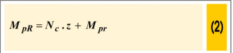
as illustrated in igures 1.d and 1.e. The tensile normal force Nat in the sheeting is divided into the forces Na and Nac, where Na equil-ibrates the compressive force Nc in the concrete, while and Nac counteracts the normal compressive force in the superior region of the steel sheeting. Combining the effects of these forces, the nomi-nal resistant moment can be determined using equation 2.
Figure 1.e shows that the equal and opposite normal forces Nac generate the resistant bending moment Mpr which is the effective plastic resistant moment Mpa of the steel sheeting, reduced by the effect of the tensile normal force Na = Nc. The relationship between Mpr/Mpa and Nc/Npa depends on the sheeting geometry and,
accord-ing to EUROCODE 4 (2004), can be calculated by equation 3.
The compressive normal force Nc in the concrete shown in igure
1.d is smaller than Ncf : therefore, the height of compressive stress block in the concrete is given by to equation 4.
The lever arm z is variable and depends on the relation Nc/Npa.
For intermediary situations, where , the lever
arm z can be calculated according to equation 5.
where evvaries with respect to Nc/Npa ratio. The value of ev can be estimated by the linear relationship shown in equation 6.
4. test Set-up and instrumentation
The loading apparatus consisted of steel beams as shown in ig
-ure 3. A hydraulic ram, attached to a steel frame, was used to ap -ply load to the system of steel beams. Each composite slab was tested as simply supported with two line loads equidistant from the end supports. Under each line load, rubber pads were used to dis-tribute the loads uniformly. Any undesirable longitudinal restriction was eliminated by the roller and pin supports acting together with the spherical hinge under the hydraulic ram.
The loading scheme was monotonic. Midspan delections and
end slips at both supports were measured at each load step.
Strains in the upper and lower portion of the steel sheeting at
midspan were also evaluated. A computerized data acquisition system was used.
In each test, a pre-load was initially applied to the composite slab.
After the removal of this pre-load, the irst displacement and strain
128 IBRACON Structures and Materials Journal • 2009 • vol. 2 • nº 2
5. test results and analysis
In all the tests, the irst visible cracks formed in the proximities of the
line loads. From this instance on, extensive cracking was noticed in between the two line loads.
A typical load versus midspan delection relationship is shown in ig
-ure 4 for two different specimens: Series A prototype 2 and Series B
prototype 4. The analysis of these results indicates that both slabs have initially a larger stiffness. With increasing loads, cracking on the concrete occurs reducing the slabs rigidity and consequently
generat-ing larger midspan delections for the same load increment. The limit established by EUROCODE 4 (2004) for the maximum delection in
service (span/250) is equal to 7.2 mm in this case. The corresponding
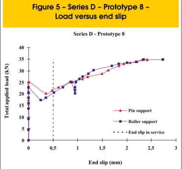
measured loads to this limit were about 37 kN for both specimens. The load versus end slip relationship for prototype 8 of Series D is pre
-sented in igure 5. This plot shows at irst null values for both end slips
indicating complete chemical bond and full composite action between the concrete and the steel sheeting. After the concrete has cracked, partial interaction occurs since the chemical bond is lost and the me-chanical interlock mechanism, provided by the embossments, is not strong enough to transfer the total shear stresses between the sheet-ing and the concrete. Consequently, there is a relative displacement
or slip between them. This behavior is characteristic of the proiled
steel sheeting used herein and was observed in all tests.
sheeting for prototype 5 of Series C. These strains were mea
-sured in the upper and lower ibers. Tensile strains have posi -tive values while compressive ones nega-tive. As expected, the
lower iber exhibited tensile strains up to failure. The upper iber, on the other hand, showed a reversal in its strain from
tension to compression. This compressive strain value in the
upper iber indicates the existence of a second neutral axis be
-low the sheeting top iber, which characterizes partial interaction behavior and the low shear transfer eficiency provided by the
embossments, used, which in turn cause the slip between the concrete and the steel-deck.
It is interesting to point out that the failure mode in all cases was shear bond. This rupture mode is characterized by the shear con-nection failure between the embossments in the sheeting and the concrete along the shear span. Although composite action was lost, the concrete, in no instant, became completely separated from
the steel sheeting as shown in igure 7. In other words, the shear
transfer mechanism provided by the embossments was capable of holding concrete and sheeting together even after the ultimate load was reached.
The composite slab test results are present in table 2. In the table, Pue corresponds to the ultimate applied load, SWslab the com-posite slab self-weight and VUT the ultimate shear force per meter of width.
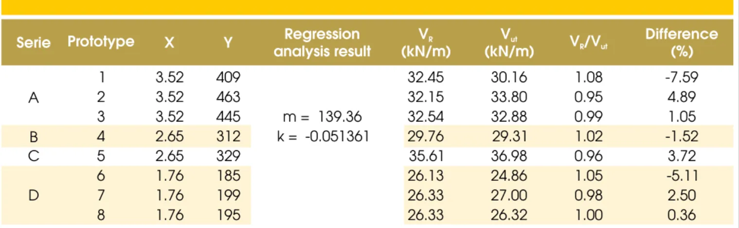
Based on those test results, the values of and
necessary to the m-k method were calculated
as previously described. The values of the slope m and of the intercept k of the equation
(
Y
=
m
.
X
+
k
)
were determinedby linear regression. Substituting these values in the equation 1,
the resistant shear force VR for each slab was calculated. These values are next compared to the test measured ones in order
to evaluate their correlation. Table 3 presents all these results
and comparison.
The Canadian Steel Sheet Building Institute (CSSBI, 2002) recom -mends that the ratio of the resistant shear force VRtotest mea-sured valueVUT for each specimen shall be between the limits from 0.85 to 1.15. If the VR/VUT ratios are outside these limits, m
andk must be reduced by 5 %. As it can be seen in the table 3, the found ratios in all cases are within those limits.
Before applying the partial interaction method, it is necessary ini-tially to determine the position of the neutral axis epand the value of the plastic moment Mpa of the steel sheeting. In determining the values, the concrete average compressive strength was set equal
to 30.5 MPa, while the yield strength and modulus of elasticity of the steel in the sheeting to 345 MPa and 200233 MPa respectively.
The position of the neutral axis epand the value of the plastic mo-ment Mpa were calculated according to ABNT NBR 14762 (2001) prescribed procedure. Due to the existence of the embossments, a reduction in the sheeting cross-sectional area was considered. The values determined for ep (measured from the lower iber) and Mpa were 25.7 mm and 10.11654 kNm/m, respectively.
The test result for each specimen as well as the degree of shear
130 IBRACON Structures and Materials Journal • 2009 • vol. 2 • nº 2
test ultimate bending moment under the line load. The mean value
for the resistant shear stress, τu, is equal to 0.1006 MPa, the
corre-sponded standard deviation, σ, equal to 0.0224 MPa; consequently, the variation coeficient is then equal to 22.3 %.
The validation of the value of the mean resistant shear stress τu
is made by the comparing each specimen ultimate resistant shear force determined with this stress with its test ultimate shear force. For the determination of each specimen ultimate resistant shear
force, equation 9 must be modiied into equation 10.
Thus, each specimen resistant bending moment is given by equation 11.
where the lever arm z is evaluated by the equation 7 and Mprby
the equation 3. In equation 3, Nc is taken according to the equation
10 and Npaequal to Ap . fy. The relation between this resistant mo-ment and the resistant shear force is equal to . Therefore, the calculated resistant shear force can be determined by the equation 12.
Table 5 presents the results of comparative analysis between the calculated resistant shear force determined according to equation 12, using the average value of resistant shear stressτuand friction
coeficient µ equal to 0.5, with respect to the test ultimate shear
procedures is equal to 4 %, which indicates that both methods pro-duce very similar results.
6. Concluding remarks
The overall analysis of the test results of the composite slabs built with steel-deck MF-50 revealed that initially there is a full
compos-ite action between proiled steel sheeting and the concrete. With
increasing loads, concrete cracking occurs accompanied by the breakdown in the chemical bond between the sheeting and the concrete. From this point onwards, partial interaction behavior is
observed since the proiled sheeting embossments are unable
to transfer the total shear stresses between the sheeting and the concrete. Consequently, there is a relative displacement or slip be-tween them. In all cases, the failure mode was by shear bond. Based on this failure mode, the m-k method and partial interaction method, prescribed by ABNT NBR 8800 (2008), for calculating the composite slab shear strength were analyzed. For determining the ultimate resistant shear force, the partial interaction method is an alternative to the m-k procedure especially when shear connectors or additional longitudinal reinforcing bars are used. The resistant shear forces were determined according to these two methods.
The ultimate resistant shear forces calculated by both methods are very similar indicating that both procedures provide safe and reli-able results.
7. acknowledgments
The authors would like to thank METFORM S. A. and Coordena
-ção de Aperfeiçoamento de Pessoal de Nível Superior (CAPES) for their support and inancial aid.
8. references
[01] ASSOCIAÇÃO BRASILEIRA DE NORMAS TÉCNICAS (ABNT) - nBr 8800 – “Projeto de estrutura de aço e de estrutura Mista de aço e Concreto de edifícios”, 2008, Rio de Janeiro, Brazil.
[02] ASSOCIAÇÃO BRASILEIRA DE NORMAS
TÉCNICAS (ABNT) - nBr 14762 – “Dimensionamento
de Estruturas de Aço Constituídas por Peris
Formados a Frio”, 2001, Rio de Janeiro, Brazil.
132 IBRACON Structures and Materials Journal • 2009 • vol. 2 • nº 2
com fôrma de aço incorporada”, Master’s
Dissertation in Structural Engineering, Federal
University of Minas Gerais, 2007, Belo Horizonte, Brazil. [04] CALIxTO, J. M., LAvALL, A. C., MELO, C. B.,
PIMENTA, R. J., e MONTEIRO, R. C., “Behaviour and Strength of Composite Slabs with ribbed Decking”,Journal of Constructional Steel Research,
v. 46, n. 1-3, p. 211-225, 1998, London,
United Kingdom.
[05] CANADIAN ShEET STEEL BUILDING INSTITUTE
(CSSBI) – “CSSBi S2-2002:Criteria for the testing of Composite Slabs”, 2002, Cambridge, Canada. [06] EUROPEAN COMMIITTEE FOR
STANDARDIZATION - eUroCoDe 4 – “Design of Composite Steel and Concrete Structures – Part 1.1: General rules and rules for buildings”, 2004, Brussels, Belgium.
[07] JOhNSON, R. P. - “Composite Structures of Steel and Concrete– vol. 1”, Blackwell Scientiic
Publications, Segunda Edição, 1994, Oxford, London,
United Kingdom.
[08] LOPES, E. e SIMõES, R., - “experimental and analytical Behaviour of Composite Slabs”, Steel
and Composite Structures, v.8, n. 5, p.361-388, 2008,