Attack Model
Implementation for a
Secure Onboard
Communication from
an Automotive ECU
Patrick Alexandre Almeida Grümer
Mestrado em Segurança Informática
Departamento de Ciência de Computadores 2019
Orientador
Pedro Brandão, Professor Auxiliar, Faculdade de Ciências da Universidade do Porto
Coorientador
Todas as correções determinadas pelo júri, e só essas, foram efetuadas.
O Presidente do Júri,
Abstract
Digital security is becoming increasingly more complex and thus important in the automotive industry. This research was part of a master’s dissertation work to evaluate the security measures
defined by the Automotive Open System Architecture (AUTOSAR) Security Concept for the
implementation of the authenticity, reliability, and integrity of the transmitted and received data over communication buses. It begins with a brief introduction about the evolution of the
automotive industry in recent decades, and follows-up with the AUTOSAR architecture and
Security concept; then, it provides a short explanation about the product security life cycle using the V-model development process. Subsequently, it poses some automotive security concerns and it presents solutions to them, in an attempt to improve the future of the automotive security.
In addition, an overview of the AUTOSAR module Secure Onboard Communication (SecOC)
is provided to understand how a secure communication based on authenticity, and integrity is established nowadays.
To identify security issues related with the communication bus of the in-vehicle network of the car, and to identify mechanisms which may mitigate these issues or discourage a potential threat, a pentesting framework was developed. Its aim is to evaluate the need of security measures in specific in-vehicle network protocols, and, if those security measures exist, audit their strength to detect poor implementation.
With this approach, we concluded that the nonexistence of security measures in the Scalable
service-Oriented MiddlewarE over IP Service Discovery (SOME/IP-SD) protocol could open up
a vector of attack. This absence of security enables an attacker to search, provide, or subscribe to a service, and, in the worst-case scenario, it allows him to terminate services provided by other
Electronics Control Units (ECUs) of the network. Furthermore, we concluded that although
there are some cases where security measures do exist, the poor implementation still enables any attacker the ability of performing a replay attack.
Resumo
A segurança digital está a tornar-se cada vez mais complexa e, portanto, importante na indústria automóvel. Este estudo fez parte de um trabalho desenvolvido numa dissertação de mestrado para avaliar as medidas de seguranças definidas pelo Automotive Open System Architecture
(AUTOSAR) Security Concept que garantem uma implementação da autenticidade, fiabilidade e
integridade dos dados transmitidos e recebidos através do barramento de comunicação. Inicia com uma breve introdução sobre a evolução da indústria automóvel nas últimas décadas, explicando
também a arquitectura e segurança do AUTOSAR. Em seguida, é dada uma breve explicação
sobre o processo de desenvolvimento de um produtos ou software seguros baseado no V-model. Além disso, são apresentadas as preocupações de segurança e algumas soluções para o futuro no ramo automóvel. Para terminar, é apresentada uma visão geral do módulo Secure Onboard
Communication (SecOC) do AUTOSAR, para se entender como uma comunicação baseada em
autenticidade e integridade é estabelecida actualmente.
Assim, para identificar problemas de segurança relacionados ao barramento de comunicação da rede dos carros e para determinar mecanismos que possam ser capazes de mitigar este tipo de problemas, foi desenvolvida uma framework de pentesting. Esta framework tem como objectivo avaliar a necessidade de medidas de segurança em certos protocolos e, se essas medidas de seguranças existirem, auditar a sua qualidade de implementação.
Com esta abordagem foi concluído que a inexistência de medidas de segurança no protocolo
Scalable service-Oriented MiddlewarE over IP Service Discovery (SOME/IP-SD) cria uma
oportunidade de ataque. A ausência de medidas de segurança permite a um atacante procurar, fornecer, ou mesmo subscrever a um serviço e, num cenário mais catastrófico, permite que termine
serviços de outros Electronics Control Units (ECUs) da rede. Por último, também foi concluído
que, embora existam alguns casos em que existem medidas de segurança, a fraca implementação das mesmas permite a um atacante executar um Replay Attack.
Acknowledgements
First, I would like to thank my University mentor Professor Pedro Brandão, and in particular my enterprise friend, and mentor Ivo Brandão for their invaluable advice and input. I have enjoyed our regular meetings, and it was crucial to the quality of my work. Also, I want to give a special thanks to my friend, and work colleague Paulo Martins for the support.
Seccond, I would like to thank everyone of my family, especially my father, sister, and cousins (Rodrigo Duarte, Susana Duarte, and Pedro Duarte), who made this dissertation a reality.
Third, I would like to thank to my girlfriend (Sofia Moreira), and all the close friends for all the support during this year. A special thank to João Salvado for the help in reviewing the dissertation.
Finally, I would like to give a special thank to all those who made this dissertation possible, and it should be noted that all that was accomplished is just the beginning.
Patrick Grümer, Braga, May 2019
Contents
Abstract i Resumo iii Acknowledgements v Contents ix List of Tables xiList of Figures xiv
Listings xv
Acronyms xvii
1 Introduction 1
1.1 Motivation and Problem . . . 2
1.1.1 Goals . . . 3
1.1.2 Outline . . . 3
2 Background 5 2.1 Evolution of Automotive Network topologies. . . 5
2.2 Automotive Protocols . . . 9
2.2.1 OSI Model . . . 9
2.2.2 Communication. . . 10 vii
2.3 AUTOSAR . . . 14
2.3.1 AUTOSAR Layered Architecture . . . 14
2.3.2 AUTOSAR Interfaces . . . 16
2.4 AUTOSAR Security concept . . . 18
2.4.1 AUTOSAR Communication Stack . . . 19
2.4.2 AUTOSAR Crypto Stack . . . 24
2.4.3 Security Extensions . . . 25
2.5 Security Engineering . . . 26
2.5.1 Product Security Life Cycle . . . 26
2.5.2 Assets . . . 27
2.5.3 Threat Analysis and Risk Assessment . . . 27
2.5.4 Secure Software Development . . . 31
3 State of the Art 33 3.1 Automotive Security concerns . . . 34
3.2 The Future of the Automotive Security. . . 35
3.3 Automotive Security Testing Techniques . . . 37
4 Secure Onboard Communication 41 4.1 Authentic I-PDU and Secure I-PDU . . . 42
4.2 Authenticator . . . 42
4.3 Freshness Value . . . 43
4.4 Safe and Secure Communication Concept . . . 43
4.4.1 End-to-End Protection. . . 44
4.4.2 Secure Onboard Communication - Authentication & Verification . . . 45
5 Core Test Framework - Information Gathering and Attacking 49 5.1 Hardware . . . 49
5.2 Network . . . 50
5.2.1 NMAP & Metasploit . . . 50
5.2.2 Network Analysis. . . 51
5.3 Core Framework . . . 52
5.3.1 The in-vehicle Network . . . 52
5.3.2 Test Specifications . . . 54
5.3.3 Core Framework Architecture . . . 55
6 Findings, results, and Data Analysis 57 6.1 Sniffing Attack . . . 57
6.2 ARP Spoofing Attack . . . 58
6.3 SOME/IP Service Discovery Attack . . . 59
6.4 Service Events Attack - Authenticity and Integrity . . . 61
7 Conclusions 63 7.1 Future Work . . . 64 A Wireshark Report 65 B Test Specification 71 Bibliography 75 ix
List of Tables
2.1 STRIDE . . . 30
2.2 Threat Analysis Example . . . 31
List of Figures
2.1 The growth in the use of electronic components in the automotive industry [33] . 6
2.2 Future domain based architecture [29] . . . 7
2.3 Ethernet backbone in domain architecture [40] . . . 8
2.4 The TCP/IP model vs The OSI model . . . 10
2.5 OSI Message flowing . . . 11
2.6 Protocols that are use in the automotive industry per Use Case . . . 13
2.7 First approach to the AUTOSAR layer organization . . . 15
2.8 AUTOSAR BSW layer organization . . . 16
2.9 Automotive Open System Architecture (AUTOSAR) Interface [2,78]. . . 17
2.10 Standardized AUTOSAR Interface [2,78] . . . 17
2.11 Standardized Interface [2,78] . . . 18
2.12 AUTOSAR Basic Software (BSW) detailed with the stacks . . . 18
2.13 Ethernet, Controller Area Network (CAN), Local Interconnect Network (LIN), FlexRay Stacks Flow . . . 22
2.14 Ethernet Stack Flow . . . 24
2.15 Ethernet Stack, and Crypto Stack Flow . . . 25
2.16 V-Model . . . 27
2.17 Generic risk model [50]. . . 28
2.18 Generic risk assessment process [50] . . . 28
2.19 Software Development Lifecycle (SDLife) Diagram [56] . . . 29
2.20 SDL [56]. . . 30
3.1 Internet-of-Things (IoT) [31] . . . 33
3.2 Future connected cars [48] . . . 34
3.3 Multi-Level Security Approach [79] . . . 36
3.4 4-Layer Cyber Security Solution [73] . . . 37
3.5 Automotive Security Solution [43]. . . 38
4.1 Secured Interaction Layer Protocol Data Unit (I-PDU) Structure [20] . . . 42
4.2 Message Authentication Code (MAC) generation [20] . . . 43
4.3 E2E Protection [11] . . . 44
4.4 Authentication Process [11] . . . 46
4.5 Authentication Process [11] . . . 47
5.1 Reference Design - MC33812 / S12P Small Engine Control [61] . . . 50
5.2 Host discovery, Port scanning, and Metasploit used in the in-vehicle network . . 51
5.3 Security Trust Boundaries [41] . . . 52
5.4 Man-in-the-Middle (MitM) attack . . . 53
5.5 Test Specification Sniffing . . . 54
5.6 Core Framework Design . . . 55
5.7 Core Framework Class Diagram with dependency’s . . . 56
6.1 Message events of the service . . . 59
B.1 Test Specification Sniffing . . . 71
B.2 Test Specification Address Resolution Protocol (ARP) Spoofing . . . 72
B.3 Test Specification SOME/IP SD . . . 73
B.4 Test Specification Replay Attack Events . . . 74
Listings
6.1 ARP Spoofing Report . . . 58
6.2 SOME/IP SD Report . . . 60
6.3 Events of the Services Simple Report . . . 61
A.1 SOME/IP SD Complete Report. . . 65
A.2 Events of the Services Complete Report . . . 67
Acronyms
ADAS Advanced Driver Assistant Systems
ADC Analog to Digital Converter
AES Advanced Encryption Standard
AES-CMAC Cipher-based Message
Authentication Code
AES-HMAC Hash-based Message
Authentication Code
API Application Programming Interface
APIs Application Programming Interfaces
ARP Address Resolution Protocol
AUTOSAR Automotive Open System
Architecture
BSW Basic Software
BswM Basic Software Mode Manager
CAL Crypto Abstraction Library
CAN Controller Area Network
CAN-FD Controller Area Network Flexible
Data-Rate
CDD Complex Device Driver
COM Communication Signal Based
Gateway
ComM Communication Manager
CRC Cyclic Redundancy Check
CryIf Crypto Interface
CSM Crypto Service Manager
DCM Diagnostic Communication Manager
DHCP Dynamic Host Configuration Protocol DHCP Dynamic Host Configuration Protocol
DoIP Diagnostic over Internet Protocol
DOS Denial of Services
DSRC Digital Short Range Communication
E/E Electric/Electronic
E2E End to End
ECU Electronics Control Unit
ECUs Electronics Control Units EEPROM Electrically Erasable
Programmable Read-Only Memory
EthIf Ethernet Interface
EthSM Ethernet State Manager
FV Freshness Value
FVM Freshness Value Manager
FVMaster Freshness Value management
Master ECU
HSM Hardware Security Module
HTA Hardware Trust Anchor
HTA Hardware Trust Anchors
HW Hardware
I/O Input/Ouput
ICMP Internet Control Message Protocol
IEEE Institute of Electrical and Electronics
Engineers
IKE Internet Key Exchange
IoT Internet-of-Things
IP Internet Protocol
I-PDU Interaction Layer Protocol Data Unit IPDU-M Interaction Layer Protocol Data
Unit Multiplexing
IPsec Internet Protocol Security
IPv6 Internet Protocol version 6
LdCom Large Data Communication
LIN Local Interconnect Network
LLC Logical Link Control
LSB Least Significant Bits
MAC Message Authentication Code
MAControl Media Access Control MitM Man-in-the-Middle
MOST Media-Oriented Systems Transport
MSB Most Significant Bits
ND Neighbor Discovery
NMAP Network Mapper
NVRAM Non-Volatile Random Access
Memory
OBD On-board Diagnostics
OEM Original Equipment Manufacturer
OSI Open System Interconnection
PCI Protocol Control Information
PDU Protocol Data Unit
PduR Protocol Data Unit Router
RTE Runtime Environment
S-box substitution-box
SD Service Discovery
SDL Secure Product Development
SDLife Software Development Lifecycle
SDU Service Data Unit
SecOC Secure Onboard Communication
SHE Security Hardware Extension
SoAd Socket Adaptor
SoConId Socket Connection Identified SOME/IP Scalable service-Oriented
MiddlewarE over IP
SOME/IP-SD Scalable service-Oriented
MiddlewarE over IP Service Discovery
SPN Substitution and Permutation
Network
StBM Synchronized Time-Base Manager
SUT System Under Test
SW Software
SW-C Application Software Component
SWC Software Component
SWCs Software Components TCP/IP Transmission Control
Protocol/Internet Protocol
TCP Transmission Control Protocol
TLS Transport Layer Security
Tsyn Time Synchronization
UDP NM User Datagram Protcol Network
Manager
UDP User Datagram Protocol
UDS Unified Diagnostic Services
V2V Vehicle-To-Vehicle
VFB Virtual Functional Bus
XCP Universal Measurement and
Calibration Protocol
XOR Exclusive OR
Chapter 1
Introduction
One of the most remarkable technological evolutions of the 20th century was the evolution of land-based transportation systems, in which the automotive vehicle became one of the central means of transportation.
In the past two decades, the electrification of the automotive vehicle transformed this system into a complex piece of technology. This led to an increase in the number of Electronics Control
Units (ECUs) present inside of a vehicle. A heterogeneous network ofECUs, sensors and actuators
that communicate over bus systems, provide most of the functionalities present in a vehicle, with the aim of increasing safety, security to create innovative functions in the automotive industry.
In 2003, automotive Original Equipment Manufacturer (OEM) and suppliers joined to create
a standardization initiative named Automotive Open System Architecture (AUTOSAR). The
goals of this standardization are the improvement of the Management of Electric/Electronic (E/E)
complexity associated with growth in functional scope; the flexibility for product modification, upgrade and update; scalability of solution within and across product lines; the improvement of
quality and reliability of E/E systems. These standardizations facilitate the creation of a basis
for future vehicle applications, solving current barriers between functional domains, enabling the
existence of heterogeneous networks of ECUs, sensors, actuators, and buses.
Almost all the new functions present in the vehicle, will require the collection of data from the physical environment, in order to make automotive operation decisions, and to execute on such decisions with physical consequences. Some of these innovations include, Advanced Driver
Assistant Systems (ADAS), Advanced fleet management, Smart transportation and Autonomous
driving. The goal of the next generation of vehicles is that driverless vehicles become a reality to achieve zero fatalities and/or collisions, improve traffic flow, and other benefits. This automotive innovation is driving the need for built-in security solutions and architectural design to mitigate emerging threats. The goal for automotive security products is to ensure that the new vehicle paradigm is protected and can operate to its full potential, even in a malicious operating environment.
Automotive networks andECUswere only accessible by direct physical contact inside the
2 Chapter 1. Introduction
vehicle. Now, an attacker can break into systems with little or no physical access [68]. If the
evolution of the automotive attackers goes towards larger and more sophisticated organizations,
as Internet attackers have, this may become the norm. The proliferation of ECUs linked by
common protocols increases the attack surface, making the vehicles more accessible to attackers. With in-vehicle networks carrying operational and personally identifiable information such as location, navigation history, call history, microphone recordings, protecting messages and data over the communication bus is critical for operational security, privacy, and consumer trust.
Common protocols, such as Controller Area Network (CAN), Local Interconnect Network
(LIN), Media-Oriented Systems Transport (MOST), FlexRay, automotive Ethernet, Bluetooth,
Wi-Fi, and mobile 5G, amplify the threats, as they increase the attack vectors. Security-enhanced
ECUs can interact with security enhanced networking protocols (in-vehicle or external) to
enhance authenticity, reliability, and integrity of the transmitted data. Also, the
hardware-assisted technologies, such as Hardware Trust Anchors (HTA) help to secure networks without
significantly impeding performance, latency, or real-time response.
This dissertation focus on the AUTOSARSecurity Concept, with emphasis on the Secure
Onboard Communication (SecOC). We propose a penetration test framework to exploit common
threats, and therefore validate the authenticity, reliability, and integrity of the transmitted and
receive data over communication buses [31,33,35,39,68,74].
1.1
Motivation and Problem
The automotive industry is poised to enter a new golden age, where the key factor is the sensitive
information shared between all ECUs. With the emergence of innovative vehicle functions,
leading to the continual increase in the complexity of the automotive industry, arises the demand for the security measures to prevent and mitigate threats, that aim, to take control over this information. Therefore, ensuring security of this information, unlocks the possibility to explore
this new world, and try to transform it in a more secure industry [41,51,52,57,72].
The main focus of this research is to understand if the use case SecOC is able to ensure the security of the data, when it is needed. So, when a message is sent over the Communication Stack, and security is required, the Crypto Stack is responsible for ensuring the security of the message. That way, it is essential to understand the process, and to obtain some answers such as:
1. What are the actual automotive security concerns? And the future Solutions? 2. How is sensitive data handled in the in-vehicle network?
3. Under this scope, are the security goals authenticity and integrity suitable?
4. How it works, and what kind of tools can be found in the module SecOC?
5. What kind of approach should a clueless player have in order to obtain some kind of knowledge about an automotive system?
1.1. Motivation and Problem 3 6. What kind of attacks should be performed to evaluate the demand, and/or strength of
security measures in the in-vehicle network?
1.1.1 Goals
The main goal of this dissertation is the verification of the security measures defined by the
AUTOSARSecurity Concept, for the implementation of the authenticity, reliability, and integrity of the transmitted and received data over communication buses. This will be instantiated in the implementation of a penetration test framework, to exploit common vulnerabilities in authenticity and integrity of data.
Also, an overview of a Secure Product Development (SDL) will be given, in order to,
understand the complete development process of a secure product.
With this in mind, the goal of this dissertation is to look into the capability of the use case,
SecOC and, by developing an automated framework to pentest the hardware in-vehicle network, verifying if the use case is able to ensure the needed security goals, that is, authenticity, and integrity of the data. Therefore, the main idea behind this framework is to be able to replicate well-known cyber-attacks in order to verify if it is possible to change the normal operation of the hardware.
1.1.2 Outline
It is possible to find six more chapters: Chapter 2: The background chapter gives an overview of the evolution of in-vehicle communication networks and protocols, a summarized view will be
given of theAUTOSARArchitecture and the chapter finishes with the development processes for
a secure product; Chapter 3: State of the Art, describes the current technological revolution that is occurring in the automotive industry, this chapter explores studies that are being conducted in the automotive industry, more specifically in the security area; Chapter 4: Secure Onboard
Communication, details the inner workings of the SecOC use case, providing an example of a
full duplex communication between two ECUs; Chapter 5: Core Test Framework - Information
Gathering and Attacking, will give some ideas of techniques used by hackers to obtain knowledge about the target where they are trying to find vulnerabilities. Besides that, it contains the details about the penetration test framework, that supports some of most common exploits to check authenticity and integrity of Data transmitted between two or more parties; Chapter 6: Findings, results, and Data Analysis, describes the outcomes of the test framework tool; Chapter 7: Conclusions, The conclusions of the research.
Chapter 2
Background
This chapter gives a brief history about the automotive industry. First, a brief introduction on the evolution of the automotive network topologies, following with an introduction to the
Automotive Open System Architecture (AUTOSAR) Initiative, providing a high level overview of
theAUTOSARarchitecture and the automotive networking protocols that are already integrated
in this architecture. Afterwards, an overview of the AUTOSAR Security Concept is given, to
introduce the cryptography stack architecture specified by AUTOSARwith more detail, showing
how the security concept fits within the AUTOSAR architecture. Lastly, an introduction to the
security engineering is given to show how the security concept impacts the development of a new product.
2.1
Evolution of Automotive Network topologies
It is important to go back in time to understand the evolution of the electronic components in cars. The complexity of automotive electronics skyrocketed in the late 80s, driven by environmental awareness and fuel optimization forcing the need for a larger number of Electronics Control
Units (ECUs). In 1986, Bosch developed Controller Area Network (CAN) [33] that was a vehicle
control network which had a huge impact on the industry and became the first standard for in-vehicle networking.
The following decades were marked by a rise in the the number of electronic components inside
the vehicle. Figure 2.1 illustrates this evolution by showing the cost of electronics components
inside of the car overtime. Three decades of research and development in automotive products along with other driving factors, contributed to the rise from 10% of overall costs in 1980s’ to an estimated cost of 35% in 2020.
6 Chapter 2. Background
Figure 2.1: The growth in the use of electronic components in the automotive industry [33]
.
The growth of electronics components in the car drove the topologies to change, new buses
were added for specific use cases, such as Media-Oriented Systems Transport (MOST), Local
Interconnect Network (LIN), FlexRay. However,CAN remained the prevailing bus system for
communication betweenECUsuntil recently. However, the communication demand has increased
dramatically in recent years, and vehicle manufacturers are now reaching the limits of vehicle
networking with CAN [44].
With the search for more communication and bandwidth growths, the complexity of the car network, the search for more security, safety and entertainment solutions implies the search
for more solutions. In fact, the existing vehicle control networks such CAN,LINand FlexRay
standards were not designed to cover these increasing demands in terms of bandwidth and
scalability. Communication solutions such as MOST, are available but expensive for a broader
usage in automotive networking systems. Ethernet and Controller Area Network Flexible
Data-Rate (CAN-FD) are being introduced to provide higher bandwidth and are taking over some of
the tasks of existing bus systems. The higher bandwidth is one aspect, but also of high relevance
is the introduction of new communication paradigms [33,39,44].
The adoption of the Ethernet bus and existing Ethernet protocols in the automotive industry,
fulfills the need for higher bandwidths. As quoted in the book Automotive Ethernet [33], Ethernet
"already proved over its 40-years lifespan its ability to change, evolve and support ever-increasing bandwidth while maintaining backward compatibility with higher-level protocols and software. In 2014, Bosch and other members formed an alliance called BroadR-Reach to push for standardized
and included as part of the Institute of Electrical and Electronics Engineers (IEEE) 802.3 Ethernet
2.1. Evolution of Automotive Network topologies 7 force, abbreviated 1TPCE(using “C”, the Roman numeral for “100”). The standardization is
now in progress under IEEE Project 802 designation" higher-level protocols and software [33].
In the coming years it is expected that Advanced Driver Assistant Systems (ADAS), navigation,
multimedia and connectivity systems will become a mandatory requirement in the automotive
industry and with that rises the complexity and the need for more bandwidth. Figure 2.2
describes the evolution that is already happening in the car network, presenting the modular
version, that is, a classic network of a car where every Electronics Control Unit (ECU) has its
own application, where it is possible to encounter several domains protected by its own gateway,
and where each ECUis able to run multiple applications. In the future it is expected thatECUs
exchange data with the cloud [40].
Figure 2.2: Future domain based architecture [29]
The in-vehicle network will evolve to meet the bandwidth and scalability requirements for the next-generation of cars. So, the future generation of the Ethernet can be explained in the following main points:
1. Generation 1: The first Ethernet applications for the automotive industry offers the
possibility of diagnostics over Internet Protocol (IP), that is, On-board Diagnostics (OBD),
and the update of ECU flash memories [40].
2. Generation 2: In the 2nd generation of automotive Ethernet, ADAS, infotainment, and
camera systems are used to increase safety [40].
3. Generation 3: In this last generation Ethernet is used as a network backbone. This generation, introduces the in-vehicle networks split by domain. Each domain contains an Ethernet gateway, that is a part of a bigger hierarchical domain. Thus, forming a backbone,
8 Chapter 2. Background here the communication between domains is made over Ethernet. Other buses, such as
CAN,CAN-FD,LIN, or FlexRay can co-exist in this topology, the only difference is that if two domains need to communicate between them, the communication will be forwarded
by the Ethernet gateway using the Ethernet bus. This idea is shown in the Figure 2.3[40].
Figure 2.3: Ethernet backbone in domain architecture [40]
Nowadays, a car is able to execute complex tasks in a harmonious way because it is composed of 100 microprocessors, or more, all networked together, running up to 100 million lines of code. All of this is possible thanks to the main operations of Ethernet. Furthermore, with the arrival of the Ethernet in the automotive industry, and the bandwidths close to 10gb/s in the upcoming
years will encourage the appearance of new functionalities such as [33]:
• ADAS;
• Hybrid vehicles; • Electric vehicles; • Active safety systems;
• Lower-cost and better-integrated radar and video systems; • Faster and improved stability control systems;
2.2. Automotive Protocols 9 • Surround cameras providing real-time video data to a central control system charged with
driving the car without human involvement.
On the other hand, when talking about disadvantages, the main focus is the growth of the complexity and one of the most important is the presence of potential vulnerabilities, although these vulnerabilities are in part mitigated and well know, it is essential to follow the best practice of implementation to avoid the appearance of these threats.
2.2
Automotive Protocols
This chapter gives an overview of the automotive networking protocols, focusing on the Automotive
Ethernet protocols. First, an introduction to the Open System Interconnection (OSI) model is
given. Thus, allowing a mapping of the protocols to different layers, In order to better understand the functionalities provided by each protocol, for each use case. Secondly, an overview of the
communication between two ECUs, the sender and the receiver, highlights the overhead on
the protocol control information in each layer, in order to illustrate how the data between two applications can be exchanged using Internet protocols.
2.2.1 OSI Model
One way to explain difficult concepts and complicated systems is by creating a model behind the
system. Networking models such as the OSIsimplifies the complexity behind the internetworks,
the model defines a set of layers and a number of concepts for their use, that make designing
and understanding network concepts easier. The OSImodel has 7 layers: [33,59]:
• Layer 1 or Physical Layer: The physical layer is responsible for data encoding, signaling, transmission and reception between interfaces. This is normally handled by a hardware component called transceiver;
• Layer 2 or Data Link Layer: Logical Link Control (LLC), Media Access Control
(MAControl)1, hardware addressing, error detection and handling low-level message framing, quality of service features and defining physical layer standards can be found in this layer. This is handled by a hardware component called controller;
• Layer 3 or Network Layer: The IP protocol lives at this layer, and the forward
mechanism can be found here. The routers in a network are operating at this layer because they are responsible with the task of addressing, routing and traffic control;
• Layer 4 or Transport Layer: The Transmission Control Protocol (TCP) and User
Datagram Protocol (UDP) protocol live at this layer, and this layer is responsible for
1
10 Chapter 2. Background
enabling end-to-end communication between application processes. Transport Layer
protocols are responsible for reliable transmission of data segments between points on a network, including segmentation, acknowledgment and multiplexing;
• Layer 5 or Session Layer: As its name suggests, it is intended for establishing and managing session between software processes;
• Layer 6 or Presentation Layer: At this layer the data is manipulated in order to transform it from one representation to another. Implementations of character encoding, character translation, data compression and encryption/decryption of data are some of the examples that can be undertaken in this layer;
• Layer 7 or Application Layer: The last layer is responsible for handling application protocols, and resource sharing, which implements the user applications other high-level
functions.It is possible to find the High Level Application Programming Interfaces (APIs)
and resource sharing, which implement user applications and other high-level functions.
Figure2.4shows the Transmission Control Protocol/Internet Protocol (TCP/IP) model has
its own derivation of the OSI model. This derivation shows that theTCP/IPmodel allocates
protocols up to the application layer.
The OSI Model 7 – Application Layer 6 – Presentation Layer 5 – Session Layer 4 – Transport Layer 3 – Network Layer 2 – Link Layer 1 – Physical Layer TCP/IP Model Application Layer Transport Layer Internet Layer
Network Access Layer
Figure 2.4: The TCP/IP model vs The OSI model
2.2.2 Communication
UsingOSIterminology, protocols based in packet switching use messages to communicate between
2.2. Automotive Protocols 11
with another it begins by creating at the application layer a Protocol Control Information (PCI)
and a payload, then this information is send out into the the next layer (Layer 6), which will
convert all this information into a payload and create its own PCI. This process repeats itself up
to the physical layer, where the data is sent out to the other device.
When thePCIarrives at the Transport Layer (Layer 4), the type of protocols changes and
the TCP/IP protocols begins. In the Transport Layer messages are know as segments, and have the identification of a port and a protocol, that will be used to guide the segment in the next layer. In the Network layer (Layer 3) messages are know has datagrams or packets, and
here the IP address comes up. After this long run, the Data Link Layer (Layer 2) defines the
latest details needed like theMAControladdress, that identifies the hardware that have establish
communication and have sent out the message. In the end, the message that will be send out, is know has a frame and has all the detailed needed to identify the destination and the origin of the message. When the message arrives the other device, will perform the reverse process to
redirect the message into the correct application address. Figure 2.5 show us this flow of the
information [33].
Figure 2.5: OSI Message flowing
Continuing this flow of information, when aPCIarrives the application layer depending on
the specific protocol that was used it will define the next path. Therefore, the following points gives an introduction to each protocol and the specific use case that it fulfills:
• Measurement, Stimulation and Calibration:
– Universal Measurement and Calibration Protocol (XCP): The XCP is a protocol
designed to have an efficient communication between a master and a slave, with the capability of providing the following features: Synchronous data acquisition
12 Chapter 2. Background (measurement); Synchronous data stimulation (for rapid prototyping); Online memory
calibration (read/write access); Calibration data page initialization and switching;
Flash Programming for ECU development purposes; various communications busses
are supported [27];
• Diagnostics Access:
– Unified Diagnostic Services (UDS): The UDSis a protocol that defines the diagnostic services requirements needed to establish a connection between a diagnostic tester
(User) and an on-vehicle ECU(ECU, Server). Therefore, the client is able to control
the diagnostic functions such as: Electronic fuel injection; automatic gear box; anti-lock
braking system; among other functions [46];
– Diagnostic over Internet Protocol (DoIP): The DoIPis a protocol that defines the diagnostic services requirements needed to establish a connection between an external
test equipment and vehicle electronic components using IP, additionally, TCP and
UDP are used here. Some of the features that can be find are: Vehicle network
integration (IP address assignment); vehicle announcement and vehicle discovery;
vehicle basic status information retrieval (e.g. diagnostic power mode); connection establishment (e.g. concurrent communication attempts), connection maintenance and vehicle gateway control; data routing to and from the vehicle’s sub-components;
error handling (e.g. physical network disconnect) [45].
• Communication:
– Scalable service-Oriented MiddlewarE over IP (SOME/IP) Transformer: TheSOME/IP
is a communication protocol that specifies an automotive mechanism for client/server communication which supports remote procedure calls, event notifications and the
underlying serialization/wire format [22,24].
• Service Discovery:
– Scalable service-Oriented MiddlewarE over IP Service Discovery (SOME/IP-SD): The
SOME/IP-SD is a protocol used to discover the availability of the services in the in-vehicle communication, and the control of the behavior of the event messages. Some of the features that can be find are: Locate service instances; Detect if service
instances are running; Implement the Publish/Subscribe handling [23].
• Network Management:
– UDPNetwork Manager: TheUDP Network Manager is a protocol that is responsible
to coordinate the changeover between normal operation and bus-sleep mode [26].
• Address Configuration:
– Dynamic Host Configuration Protocol (DHCP): The DHCPis a Protocol that is used
2.2. Automotive Protocols 13
framework that passes configuration information to host on a TCP/IPbased network
[64].
• Address Resolution, Signaling:
– Internet Control Message Protocol (ICMP): The ICMPis a protocol that is used to
provide the basic support of IP, therefore, error reports are generated to detect errors,
for example, in the datagram processing [47];
– Address Resolution Protocol (ARP): The ARP is a protocol responsible for all the management of the addresses that a machine have had contact with it. The protocol provides a table of dynamic or static addresses that defines the knows hosts based on
IP [38];
– Neighbor Discovery (ND): The ND is a next generation protocol for IP, it uses
ICMP andARP. It provides the following features: node address autoconfiguration;
discovery of other nodes in the local network; determination of addresses of other nodes; detection of duplicate addresses; maintenance of the information about the
other neighboring nodes that are active [76].
In summary, figure2.6illustrates several use cases used in the automotive industry, with the
allocation of the protocols in each use case. It is also possible to see an allocation of the protocols
on the layer provided by the OSImodel in order to better understand the protocol purpose.
Physical Data Link Network Transport Session Application Presentation Diagnostics Access Audio / Video Time Sync Communication Service Discovery Address Configuration Address Resolution, Signaling DoIP TP ISO 13400-2 TCP / UDP IPv6 /IPv4 UDP
IEEE 802.3 Ethernet MAC + VLAN (IEEE 802.1Q)
Ethernet Physical Layer UDS ISO 14229-5 SomeIP SomeIP-TP /SomeIP SomeIP Transformer SomeIP Service Discovery (Some/IP-SD) DHCPv4 DHCPv6 ICMPv4 ICMPv6 ARP NDP Use Case IEEE 1722 (AVB-TP) IEEE 802.1AS (gPTP) API Measurement, Stimulation and Calibration XCP UDP NM API Network Management 1 2 3 4 5 6 7
14 Chapter 2. Background
2.3
AUTOSAR
AUTOSARwas developed to create a common standardized software architecture for the
automot-ive industry. Therefore, this section will cover an explanation about theAUTOSARarchitecture,
and in addition, it will introduce the interfaces fromAUTOSAR, that are responsible for creating
an abstraction between components. This allows the standardization of communication between
the software components, that follows the AUTOSARspecification.
2.3.1 AUTOSAR Layered Architecture
In order to understand the AUTOSAR layers Architecture it is important to realize its
or-ganization abstraction. This high-level abstraction is based on a 3-layered architecture model,
that provides a mechanism for transmitting information between ECUs. Apart from that, the
AUTOSARstandard specifies the application layer implementation using a “component” concept.
Starting, with the Application Layer which is the topmost layer within anAUTOSARsoftware
architecture, and it is considered to be critical for all vehicle applications, it is essential to
understand the “component” concept of the application layer, that is the AUTOSARapplication
software component. A typical End to End (E2E) communications depends on each system. In
AUTOSAR, the implementation of the functionality for this system is done in a module called
Application Software Component (SW-C). The objective of these SW-Care done in the entity
called Runnable, which are basically the procedures that contain the actual implementation of
the software component. This layer is responsible to run the application on the ECU, and have
several important features such has [35,37,42]:
• It is not specified byAUTOSAR;
• Applications are developed by the supplier denominated Extensions, with have their own rules;
• Applications are ECUindependent, so they can be reusable in any ECU.
The Runtime Environment (RTE) creates an abstraction between the Application Layer and
the Basic Software (BSW). All the communications areECU-specific since they depend on the
specification of theECU to access the correct channel [35].
Lastly, it is possible to encounter the BSW, this layer is composed by the ECU specific
modules, and genericAUTOSAR modules. In this way, theBSW, can be divided into four more
layers: Service layer; ECU abstraction layer; microcontroller abstraction layer; and complex
2.3. AUTOSAR 15
• Input/Ouput (I/O): access to sensors, actuators and ECUonboard peripherals [2];
• Memory: access to internal/external memory; • Communication access to:
– Vehicle network systems;
– ECU onboard communication systems;
– ECU internal Software.
• System: Operation system, timers, error memory, ECUstate management, ECU watchdog
manager, services and library functions.
Hardware
Runtime Environment (RTE)
Application layer A UT O SA R Li br ar ie s Basic Software (BSW)
Figure 2.7: First approach to the AUTOSAR layer organization
In order to go into more detailed aboutBSW, and starting with the Service Layer, here it
is possible to find the needed basic software module, and the service layer is responsible for providing basic services to the applications. So, it is possible to find the following services: operational system; vehicle network communication and management services; memory services
(Non-Volatile Random Access Memory (NVRAM) management); diagnostic services (Including
UDS communication; error memory and fault treatment);ECU state management.
Reaching the middle point of the Basic Software Layer, the ECU Abstraction Layer, that
creates an abstraction between the higher software layers and the ECU hardware layout, it
offers an Application Programming Interface (API) to access peripherals and devices regardless
of the location (microcontroller internal/external) and their connection to the microcontroller (port pins, type of interface). In other words, an interface exists to abstract the communication between the hardware and software managing the drivers. Drivers can be describe as code that is used to control the access to an internal or external device. When they are internal devices they are located inside the microcontroller, and they can also be called internal driver (Internal
16 Chapter 2. Background
Internal Analog to Digital Converter (ADC)) or they can be outside of the microcontroller in
the ECU Abstraction Layer and called external devices.
Beyond that, when there are more elaborated drivers, the complex driver layer, in the right side is used to special functional and timing requirements for handling complex sensors and actuators.
In the lowest level of the Basic Software, the Microcontroller Abstraction Layer, that is, responsible of making the higher software layers independent of the microcontroller. As explained above, the internal drivers can be found here, which are software modules with direct access to
the microcontroller peripherals and memory mapped microcontroller external devices [2].
Hardware
Runtime Environment (RTE)
Application layer A UT O SA R Li br ar ie s
Microcontroller Abstraction Layer System Service
ECU Abstraction Layer Complex Driver
Figure 2.8: AUTOSAR BSW layer organization
2.3.2 AUTOSAR Interfaces
When it comes to hardware, software, peripheral, humans and/or a combination it is important
to think how they should communicate. AUTOSAR, creates an abstraction that makes it
possible for the interaction between two or more separate components. AUTOSAR interfaces
are provided by theRTE and creates an interface between Software Components (SWCs) and
the ECU firmware. These interfaces give the capability to read input values and write output
values [2,78]. AUTOSAR distinguishes between three types of interfaces:
• AUTOSARInterface: It is generated together with theRTEand it is an application-specific, that enables, data exchange in the application layer;
2.3. AUTOSAR 17 SWC: Left Door AUTOSAR Interface Door ECU
…
SWC: Left Contact AUTOSAR Interface RTE Standardized Interface Operating System St an d ar d ized In te rfa ce Standardized AUTOSAR Interface Services Standardized Interface Standardized Interface Communication Standardized Interface AUTOSAR Interface ECU Abstraction Standardized Interface Complex Device Drivers Standardized AUTOSAR interface Microcontroller Abstraction ECU HARDWARE AUTOSAR InterfaceFigure 2.9: AUTOSAR Interface [2,78]
• Standardized AUTOSAR Interface: It is provided by the BSW modules in the Service
Layer inside the modules ECU Manager and the Diagnostic Event Manager, and these
types of interfaces are used by the SWCsfor access toAUTOSAR Services;
SWC: Left Door AUTOSAR Interface Door ECU
…
SWC: Left Contact AUTOSAR Interface RTE Standardized Interface Operating System St an d ar d ized In te rfa ce Standardized AUTOSAR Interface Services Standardized Interface Standardized Interface Communication Standardized Interface AUTOSAR Interface ECU Abstraction Standardized Interface Complex Device Drivers Standardized AUTOSAR interface Microcontroller Abstraction ECU HARDWARE AUTOSAR InterfaceFigure 2.10: Standardized AUTOSARInterface [2,78]
• Standardized Interface: It is an interface given by the AUTOSAR standard as an API
written in C language. The interface abstraction provides a door between two options:
1. RTEand the Operation System;
18 Chapter 2. Background SWC: Left Door AUTOSAR Interface Door ECU
…
SWC: Left Contact AUTOSAR Interface RTE Standardized Interface Operating System St an d ar d ized In te rfa ce Standardized AUTOSAR Interface Services Standardized Interface Standardized Interface Communication Standardized Interface AUTOSAR Interface ECU Abstraction Standardized Interface Complex Device Drivers Standardized AUTOSAR interface Microcontroller Abstraction ECU HARDWARE AUTOSAR InterfaceFigure 2.11: Standardized Interface [2,78]
2.4
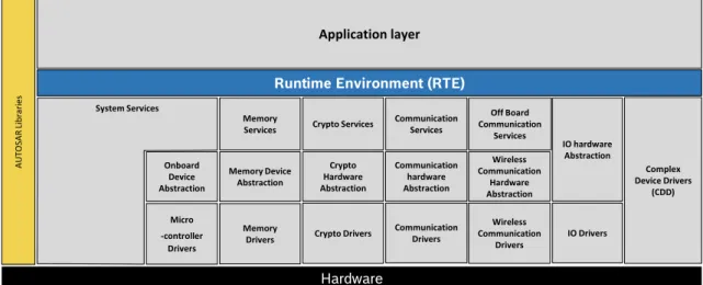
AUTOSAR Security concept
Within the BSW, it is still possible to go into more detailed, and divide it into stacks. The
communication stack is responsible for providing communication services in the BSW, and
when security is needed the Crypto Stack complements the work of the Communication Stack, providing cryptographic tools to ensure authentication based in authenticity and integrity of the messages.
Hardware
Runtime Environment (RTE)
Application layer A UT O SA R Li br ar ie s System Services Onboard Device Abstraction Micro -controller Drivers Memory Drivers Memory Device Abstraction Memory Services Crypto Drivers Crypto Hardware Abstraction Crypto Services Communication Drivers Communication hardware Abstraction Communication Services Wireless Communication Drivers Wireless Communication Hardware Abstraction Off Board Communication Services IO Drivers IO hardware Abstraction Complex Device Drivers (CDD)
2.4. AUTOSAR Security concept 19
2.4.1 AUTOSAR Communication Stack
AUTOSAR Communication Stack is composed by a set of modules that are responsible for providing the necessary tools for the communication of data, independently of the bus type (CAN,CAN-FD,LIN, FlexRay,MOSTor Ethernet).
The research focuses on the Ethernet specification; however, before approaching this specific bus, an introduction will be given of all the important modules that are common to every bus. In the Service layer, regardless of the bus, it is always possible to encounter the following modules:
• XCP: This protocol was introduce in the section 2.2.2, and it will only be mentioned again
in this section to notice, that depending on the bus, there is always a configuration possible.
So, it is always available a configuration for XCP in FlexRay, CAN and Ethernet. The
AUTOSAR XCPModule is located above the bus specific Interfaces in case of FlexRay
andCAN. On the other hand,XCPmodule Ethernet, is above the Socket Adaptor (SoAd)
[27].
• Synchronized Time-Base Manager (StBM): The purpose of the StBM is to provide a
definition of time to some BSW modules or to the applications to synchronize them. Two
main use cases are supported by the StBM[25]:
– Synchronization of Runnable Entities: Some entities need to start in a synchronous
method, for example, they need to start at the same time [25];
– Provision of absolute time value: A central module is responsible to manage and
maintain the definition of absolute time and passage of time [25];
– (Bus)Time Synchronization (Tsyn): Depending on the bus, it is important to notice
that, it is possible to find Tsynin FlexRay,CAN and Ethernet. This module handles
the distribution of time information over the specific bus.
• Protocol Data Unit Router (PduR): The PduR Router module provides services for
forwarding the Interaction Layer Protocol Data Unit (I-PDU)2 to the necessary service, that
is, Communication Signal Based Gateway (COM), Large Data Communication (LdCom),
PDU-Multiplexing, Diagnostic Control Manager,SoAd, or Secure Onboard Communication
(SecOC) [18]:
2Protocol Data Unit (PDU) is a single unit of information transmitted between two computer network parties.
TheAUTOSARuses the definitionI-PDUwhich is the same has thePDUbut adds the capability to exchange this
20 Chapter 2. Background
• Communication Signal Based GatewayCOM: The COMmodule is one of the last frontier
of the service layer. This module is responsible for transmitting or receiving data from the
RTE. The features that are offered by this module are [6]:
– provision of signal oriented data interface for the RTE;
– communication transmission control (start/stop ofI-PDUgroups);
– sending of signals according to transmission type as specified in the Virtual Functional
Bus (VFB) specification;
– guarantee of minimum distances between transmission requests; – monitoring of received signals (signals timeout);
– monitoring of transmited confirmations; – filter mechanisms for incoming signals; – different notification mechanisms;
– provision of initialization-values and update-Indications;
– packing and unpacking ofAUTOSARsignals to I-PDU to be transmitted;
– supporting large and dynamical length data types;
• Large Data CommunicationLdCom: Like theCOM,LdComis responsible for transmitting
or receiving data from theRTE, but in this case it is used when the size of the data is too
big, and the COMis not able to handle this kind of size. The features that are offered by
this module are:[17]:
– Provision of signal oriented data interface for theRTE;
– Provision of received signals toRTE;
– Support of large and dynamic length data types;
– Provision ofI-PDU oriented data interface towardsPduR. [17];
• Interaction Layer Protocol Data Unit Multiplexing (IPDU-M): TheIPDU-M module is
responsible to combine appropriate I-PDU from COM to new, multiplexed I-PDU and
send them back to thePduR. On receiver-side, it is responsible to interpret the content of
multiplexedI-PDU and provideCOMwith its appropriate separated I-PDU. TheI-PDU
multiplexing means using the samePCI of aI-PDU with more than one unique layout of
its Service Data Unit (SDU) [16].
• Diagnostic Communication Manager (DCM): The DCM is aBSW module of the
commu-nication layer. The module is responsible for the diagnostic service, that is, diagnostic requests from an external diagnostic tools during the development, manufacturing or service. Beyond that, it is responsible of ensure the diagnostic data flow and manages the diagnostic
2.4. AUTOSAR Security concept 21
• Basic Software Mode Manager (BswM): The BswM is the module that implements the
part of the Vehicle Mode Management and Application Mode Management concept that
resides in the BSW. It can be seen as a management framework module in which its
behavior depends on its configuration. The operation of the BswMbasic functionality can
be described by two different modes [5]:
– The Mode Arbitration: This module from the BswM is defined by a simple and
rule-based mode. This rules are composed of trivial Boolean expressions, and are
defined by the user in the configuration of theBswM. In the end, theBswMgenerates
an action list based on previous rule evaluation [5];
– The Mode Control: performs all the necessary actions based in the action list, that
was created in the arbitration mode [5].
• Communication Manager (ComM): The Communication Manager Module (COM Manager,
ComM) is a component of the BSW. The ComM module is responsible for managing
the communication services, and all the operations expected from the ComMmodule are:
allocation of necessary resources for the requested communication mode; switches to a communication mode as requested by the user; implement channel state machine for every channel to control more than one communication channel of an ECU.
– User Datagram Protcol Network Manager (UDP NM): TheAUTOSAR UDP NMis a
hardware independent protocol that can be used onTCP/IP based systems. Its main
purpose is to coordinate the transition between normal operation and bus-sleep mode of the network. In addition to the core functionality optional features are provided e.g. to implement a service to detect all present nodes or to detect if all other nodes
22 Chapter 2. Background HW Abstraction Layer Se rv ic e s Lay e r
Microcontroller Abstraction Layer
Runtime Environment (RTE)
PDU Router ComM NM UDP NM Et hS M Li nS M C anS M FrSM CanTP FrTP SoAd DoIP SD XCP XC P onC A N XC P onF r XC P onE th DCM COM LdCom IPDU-M DHCP UDP TCP IPv4 / IPv6 ARP ICMP NDP OS BswM
EthIf CanIf FrIf
Signal Based Gateway LinIf StbM C anT sy n Fr Tsy n Et hTsy n Application Layer
Eth Driver Can Driver FlexRay Driver Lin Driver
Security Extensions
Hardware
Figure 2.13: Ethernet,CAN,LIN, FlexRay Stacks Flow
Figure 2.13 presents various options in buses to be chosen to conduct a communication.
Ethernet is the main focus because the remaining are already well know and studies have been conducted, due to the seniority of these buses. In this way, now will be introduce the modules used by the Ethernet divided by levels of abstraction:
1. Communication Services [14,19,21]
• Protocols (IPv4/Internet Protocol version 6 (IPv6), UDP/TCP, DHCP): These
protocols are Ethernet related and are used to transmit data from the interface to the Socket Adaptor;
• Service Discovery (SD): In the AUTOSARcontext, a find is an operation to identify
available Service Instances and their locations. The main tasks of the SD Module
are managing the availability of functional entities called services in the in-vehicle communication as well as controlling the send behavior of event messages. This allows
sending only event messages to receivers requiring them. WithSDdifferentECUscan
offer Service Instances and find available Service Instances within the vehicle network.
AnECU can stop offering a Service Instance it was offering before. Service instances
are single implementations of a service that is defined by its service interface;
• SoAd: The SoAd enables I-PDU-based communication via the TCP/IP network.
ThereforeAUTOSAR I-PDUare mapped to socket connections which are configured
and maintained by SoAd. To use a socket connection for more than one I-PDU a
2.4. AUTOSAR Security concept 23
acceptance policy is specified to define whichTCP connections andUDPdatagrams
from remote nodes are accepted. Socket connections can be open automatically or manually via a request from the upper layer. For disconnection and recovery of a socket connection a policy is defined
For the abstraction of theTCP/IPcommunicationSoAddefines socket connections. A
SoAdsocket connection specifies a connection between a local socket (i.e. local address
identifier and local port) and a remote socket (i.e. remoteIPaddress and port), as well
as connection parameters like transport protocol, usage of the SoAd I-PDUheader,
buffer requirements, connection setup, transport protocol related parameters and so on. Each socket connection can be identified by a unique identifier, that is, a Socket
Connection Identified (SoConId).
• ComM:
– Ethernet State Manager (EthSM): AnECU can have different communication
networks. Each network has to be identified with a unique network handle.
TheComMrequests communication modes from the networks. It knows by its
configuration, which handle is assigned to what kind of network. In case of Ethernet, it uses the Ethernet state manager, which is responsible for the control flow abstraction of Ethernet networks.
2. Communication Hardware Abstration [13]:
• Ethernet Interface (EthIf): Provides to upper layers a hardware independent interface
to the Ethernet communication system comprising multiple different wired or wireless Ethernet controllers and transceivers. This interface shall be uniform for all Ethernet controllers and transceivers.
3. Communication Drivers [12,15]:
• Ethernet Driver: Provide to the upper layerEthIf a hardware independent interface
comprising multiple equal controllers. This interface shall be uniform for all controllers.
Thus, the upper layer EthIf may access the underlying bus system in a uniform
manner. The interface provides functionality for initialization, configuration and data transmission. The configuration of the Ethernet Driver however is bus specific, since it takes into account the specific features of the communication controller.
• Ethernet TransceiverDriver: Provide to the upper layerEthIf a hardware independent
interface comprising multiple equal transceivers. This interface shall be uniform for
all transceivers. Thus, the upper layer EthIf may access the underlying bus system
in a uniform manner. The configuration of the Ethernet Transceiver Driver however is bus specific, since it takes into account the specific features of the communication transceiver.
24 Chapter 2. Background HW Abstraction Layer Se rvi ce s Laye r
Microcontroller Abstraction Layer
Runtime Environment (RTE)
PDU Router ComM NM UDP NM Et hS M SoAd DoIP SD XCP XC P onF r XC P onE th DCM COM LdCom IPDU-M DHCP UDP TCP IPv4 / IPv6 ARP ICMP NDP OS BswM EthIf Signal Based Gateway StbM Et hTsy n Application Layer Eth Driver Security Extensions Hardware HTA
Figure 2.14: Ethernet Stack Flow
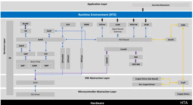
2.4.2 AUTOSAR Crypto Stack
The crypto stack is responsible for providing the necessary modules to ensure security of the communication. To better understand this stack a brief overview of the modules will be given:
1. Communication Services [9,20]:
• SecOC: Authenticity and integrity protection of sensitive data is necessary to protect the correct and safe functionality of the vehicle systems – this ensures that received
data comes from the rightECU and has not been modified;
• Crypto Service Manager (CSM): TheCSMshall provide synchronous or asynchronous
services to enable a unique access to basic cryptographic functionalities for all software
modules. The CSM shall provide an abstraction layer, which offers a standardized
interface to higher software layers to access these functionalities.
2. Communication Hardware Abstraction [8]:
• Crypto Interface (CryIf): The Crypto Interface module provides a unique interface to
manage different Crypto Hardware (HW) and Software (SW) solutions like Hardware
Security Module (HSM), Security Hardware Extension (SHE) or SW-based Complex
2.4. AUTOSAR Security concept 25
well asSWsolutions can be utilized by the CSM module based on a mapping scheme
maintained by Crypto Interface.
3. Communication Drivers [7]:
• Crypto Driver: The Crypto Drivers allow defining different Crypto Driver Objects
(i.e. Advanced Encryption Standard (AES) accelerator, SW component, etc), which
shall be used for concurrent requests in different buffers. For each hardware object a priority-dependent job processing shall be supported. A crypto software solution
(i.e. software-based CDD) can define interfaces identical to the Crypto Drivers for
interacting with the upper layers, which shall provide an interface to the applications.
HW Abstraction Layer Se rvi ce s Laye r
Microcontroller Abstraction Layer Runtime Environment (RTE)
PDU Router ComM NM UDP NM Et hS M SoAd DoIP SD XCP XC P onF r XC P onE th DCM COM LdCom IPDU-M DHCP UDP TCP IPv4 / IPv6 ARP ICMP NDP OS BswM EthIf Signal Based Gateway SecOC StbM Et hTsy n CSM CryIf Application Layer
Eth Driver Crypto Driver
Security Extensions
Hardware HTA
Crypto Driver (Sw Based) Ext. Crypto Driver
Figure 2.15: Ethernet Stack, and Crypto Stack Flow
2.4.3 Security Extensions
Security has come a long way since the initial introduction as a simple car feature. Today, the idea is to deviate from antiquated methods based on “security by obscurity”, and try to use
tools that are public domain but assure the security of the data. The AUTOSAR architecture
provides an abstraction, called security extensions, that provide a way to implement Original
Equipment Manufacturer (OEM) specific security measures for each ECU.
In conclusion,AUTOSARdoes not provide a specification for the software components that
implement the security measures, as it provides specifications for the security services to abstract
cryptographic primitives, leaving the possibility for the OEMto specify security measures which
26 Chapter 2. Background
2.5
Security Engineering
Within a world that is becoming more global and dependent on information technologies, system failures, theft or loss of data may cause an interruption, and should not be an option. Security events are costly, unpredictable and solving an incident carries out extra costs like: analyzing where the flaw is, and which systems are affected; fixing the vulnerability; reach out stakeholders and customers to explain the situation, resulting in loss of confidence by then; loss of reputation; In order to, avoid being affected these events, it is essential to understand the motivations, the several types of attackers or in more technical term Threat-Sources, that perform various
types of attacks, that in other words are called Threat Actions or Events [49]:
• Hacker or Cracker: Challenge, Ego and Rebellion access;
• Computer criminal: Destruction of information, illegal information disclosure Monetary gain, Unauthorized data alteration intrusion;
• Terrorist: Blackmail, destruction, exploitation, revenge;
• Industrial espionage: Competitive advantage, economic, espionage;
• Insiders: Curiosity, ego, intelligence, monetary gain, revenge, Unintentional errors and omissions.
Automotive industry is not different and is essential to encourage the implementation of even more demanding security policies in order to reduce this kind of events. In order to deal with this threat sources the product life cycle needs to adapted with a security mindset.
2.5.1 Product Security Life Cycle
The Security engineering is the core of any secure product. In fact, it is crucial to follow a globally accepted process that defines all the important steps, to ensure the development of a secure product.
In this section, it will be given an theoretical overview of V-Model process focusing on the essential points of the product security life cycle. The V-Model is a development process, and it is divided into three stages: Starting with the Project definition where it is defined the asset definition; Perform the Threats and Risk Assessment; Derivation of the Security Goals and Security Architecture and Mechanisms design & analysis. Lastly, there is the Project Test and Integration where after implementation, the mainly focus is in detect and mitigate bugs or vulnerabilities. With this in mind, the next subsections are intended to understand how each stage of development works.
![Figure 2.1: The growth in the use of electronic components in the automotive industry [33]](https://thumb-eu.123doks.com/thumbv2/123dok_br/19247893.974431/30.892.160.703.138.490/figure-growth-use-electronic-components-automotive-industry.webp)
![Figure 2.2: Future domain based architecture [29]](https://thumb-eu.123doks.com/thumbv2/123dok_br/19247893.974431/31.892.178.719.397.757/figure-future-domain-based-architecture.webp)
![Figure 2.3: Ethernet backbone in domain architecture [40]](https://thumb-eu.123doks.com/thumbv2/123dok_br/19247893.974431/32.892.158.737.268.649/figure-ethernet-backbone-in-domain-architecture.webp)


![Figure 2.9: AUTOSAR Interface [2, 78]](https://thumb-eu.123doks.com/thumbv2/123dok_br/19247893.974431/41.892.213.678.127.462/figure-autosar-interface.webp)