BJRS
RADIATION SCIENCES
03-1A (2015) 01-10Development and characterization of a new graphite
ionization chamber for dosimetry of
60Co beams
L. P. Neves
a; A. P. Perini
a; W. S. Santos
b; L. V. E. Caldas
baInstituto de Física, Universidade Federal de Uberlândia, 38408-100, Uberlândia-MG, Brasil
aInstituto de Pesquisas Energéticas e Nucleares, Comissão Nacional de Energia Nuclear, 05508-000, São
Paulo-SP, Brasil [email protected]
ABSTRACT
Ionization chambers are the most employed dosimeters for precise measurements, as those required in radiotherapy. In this work, a new graphite ionization chamber was developed and characterized in order to compose a primary standard system for the beam dosimetry of the 60Co sources. This dosimeter is a cylindrical type ionization chamber,
with walls and collecting electrode made of high-purity graphite, and the insulators and stem made of Teflon®. The
walls are 3.0 mm thick, and it has a sensitive volume of 1.40 cm3. The characterization was divided in two steps:
experimental and Monte Carlo evaluations. This new dosimeter was evaluated in relation to its saturation curve, ion collection efficiency, polarity effect, short- and medium-term stabilities, leakage current, stabilization time, linearity of response and angular dependence. All results presented values within the established limits. The second part of the characterization process involved the determination of the correction factors, obtained by Monte Carlo simulations. Comparing these correction factors values with those from other primary standard laboratories, the highest differences were those for the wall and stem correction factors. The air kerma rate of the 60Co source was
determined with this new dosimeter and with the IPEN standard system, presenting a difference of 1.7%. These results indicate that this new dosimeter may be used as a primary standard system for 60Co gamma beams.
1. INTRODUCTION
Primary air-kerma standards for 60Co beams are based on graphite-walled cavity ion chambers. These ionization chambers generally present cylindrical or plane-parallel design. Free-air ionization chambers are commonly utilized to measure the air kerma in x-ray beams produced with tube voltages of up to around 400 kV [1]. At higher photon energies, it is not possible to use free-air chambers, and cavity ionization chambers, or calorimeters, are employed.
In order to measure the air kerma at higher photon energies some cavity ionization chambers were developed. These ionization chambers present some advantages in relation to free-air chambers such as: small size, easy to use and they could measure multidirectional irradiation fields.
In the characterization process, of the cavity ionization chambers, some experiments and Monte Carlo simulations need to be undertaken. The experimental characterization tests are based on International Standards, while the Monte Carlo simulations are undertaken in order to determine the correction factors of the ionization chamber.
The Monte Carlo method has proven to be invaluable for radiation transport simulations, specially to determine the correction factors of the ionization chambers characterized as primary standards. Besides that, it is widely considered a reliable computational measure that can substitute a physical experiment where direct measurements are not possible [2].
In this work, a new graphite-cavity ionization chamber was developed and characterized. This new ionization chamber is part of a system of ionization chambers, intended to compose a primary standard system, for the 60Co source available at the Calibration Laboratory of the Instituto de Pesquisas Energéticas e Nucleares (IPEN) [3,4]. The experimental characterization was carried out using the IEC 60731 standard limits. The Monte Carlo simulation were undertaken in order to determine the correction factors of this new ionization chamber.
2. MATERIALS AND METHODS
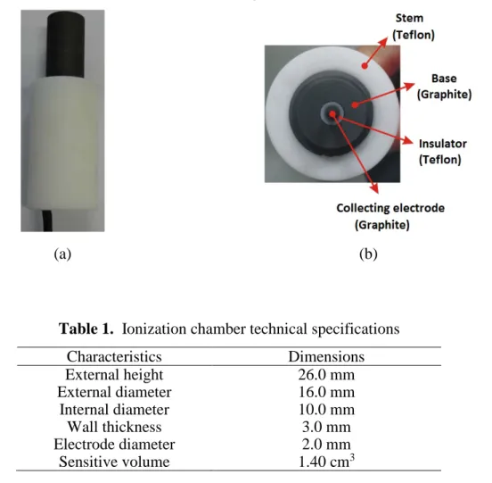
The graphite ionization chamber developed and characterized in this work is showed in Figure 1. The details of this ionization chamber are presented in Table 1.
Figure 1. Photo (a) and (b) Photo (without the wall) presenting details of the new graphite
ionization chamber developed at the IPEN. The main components are shown: stem, insulator, base and collecting electrode
(a) (b)
Table 1. Ionization chamber technical specifications
Characteristics Dimensions External height 26.0 mm External diameter 16.0 mm Internal diameter 10.0 mm Wall thickness 3.0 mm Electrode diameter 2.0 mm Sensitive volume 1.40 cm3
In the experimental measurements, the ionization chamber was attached to an electrometer, model UNIDOS E, PTW, Germany. As the chambers used in this work are unsealed, all
measurements were corrected to the reference conditions of temperature (20ºC) and pressure (101.3 kPa).
The irradiation conditions for the characterization tests were fixed at a reference field of 10×10 cm2 using a Gammatron II S80 irradiator unit.
The experimental uncertainties of all measurements obtained in this work are expanded uncertainties, obtained by the combination of types A and B uncertainties, using a coverage factor of 2.
The Monte Carlo simulations were carried out using the EGSnrc code [5] for radiation transport, in order to obtain the correction factors of the graphite ionization chamber. The spectrum utilized in the simulations was provided by the Secondary Standard Dosimetry Laboratory of Sweden [6]. The source spectrum of the Swedish laboratory was previously tested in the work of Neves et al. [7], and the results showed that it may be used to represent the equipment available at the IPEN.
The number of histories utilized in each simulation was 109. The uncertainties of all MC results are Type A uncertainties utilizing a coverage factor of 2.
3. RESULTS AND DISCUSSION
3.1. Saturation, Ion Collection Efficiency and Polarity Effect
The saturation curve was obtained with a 60Co gamma irradiator Gammatron II S80. This test
was carried out by varying the applied voltage on the ionization chamber from -400 V to +400 V, in 50 V steps, and taking ten measurements for each voltage. No significant changes
were observed in the collected charge, and therefore, the saturation was achieved in the whole tested interval (Figure 2).
Figure 2: Saturation curves of the new graphite ionization chamber developed at the IPEN for
60Co beams. The maximum uncertainty was 0.1%, and therefore not visible in the figure
The ion collection efficiency was better than 99.9%, for all tested applied voltages. The maximum value for the polarity effect was 0.4%, within the recommended limit of 1.0% [8]. Considering these results, the chosen applied voltage was +100 V for all further testes.
3.2. Short- and Medium-term Stabilities
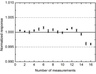
The highest variation in the short-term stability test was 0.05%, which is in agreement with the 0.3% limit [8]. For the medium-term stability test, the mean value of ten consecutive measurements was obtained, for a time period of three months, as presented in Figure 3. These values should not differ by more than 0.5% [8], which was observed.
Figure 3: Medium-term stability test of the new graphite ionization chamber developed at the
IPEN. The dashed lines represent the recommended limit of ±0.5% [8]
3.3. Linearity of Response
During this test, the absorbed doses were varied from 12 mGy to 150 mGy, and ten measurements were undertaken for each absorbed dose. The ionization chambers responses as a function of the absorbed doses were than analyzed. The correlation coefficient was 1.0000, showing that the response of the ionization chamber characterized in this work is linear in 60Co beams.
3.4. Leakage Current
The maximum value for the leakage current was 0.10% of the ionization currents measured during all tests presented in this work. This value satisfies the recommended limit of 0.5% [8].
In this test the ionization current was measured 15 min and 120 min after the connection of the dosimeter to the electrometer. These values were 99.9% of the value measured 60 min after the connection, which is in agreement with the ±0.5% variation allowed [8].
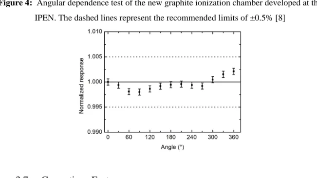
3.6. Angular Dependence
In this test, the ionization chamber was rotated around its central axis, and ten measurements were taken for each position. The results are presented in Figure 4, and it is possible to observe that all variations are within the recommended limits of 0.5% [8].
Figure 4: Angular dependence test of the new graphite ionization chamber developed at the
IPEN. The dashed lines represent the recommended limits of ±0.5% [8]
3.7. Corrections Factors
The correction factors were determined employing the EGSnrc Monte Carlo code [5]. The code presents some specific libraries, for the determination of some correction factors, as wall (Pwall)
electrode (Pelec) were determined as the ratio between the responses of the ionization chamber
without the studied component to that of the complete ionization chamber.
For the Monte Carlo simulations, the radioactive source must be represented by its spectrum. In this work, the source is a 60Co Gammatron II S80 system. Since this its spectrum and blueprints
were not available, the 60Co source at the Swedish SSDL was used [6]. This spectrum was
already used to simulate this irradiation system, as presented elsewhere [7], and also to determine some correction factors for some graphite ionization chambers, with different sensitive volumes and shapes [3,4]. The results showed that it is very suitable for this application, and therefore, it was also employed in this work. The correction factors calculated for this new dosimeter are presented in Table 2.
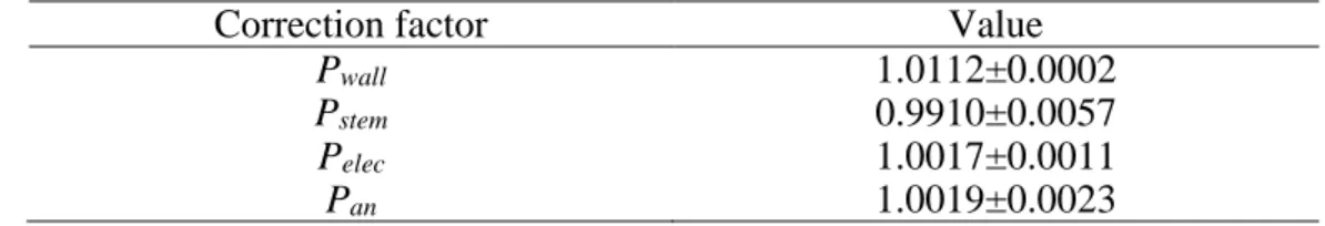
Table 2: Correction factors for the new graphite ionization chamber developed in this work
Correction factor Value
Pwall 1.0112±0.0002
Pstem 0.9910±0.0057
Pelec 1.0017±0.0011
Pan 1.0019±0.0023
3.8. Air-Kerma Rate Determination
The air-kerma rate (Kair) was determined with the use of equation (1) [9]:
∏
×
−
=
cf air wall en wall air air air air gas airP
L
e
W
g
m
I
K
ρ
µ
ρ
)
1
(
(1)where Igas is the electric current measured in the ionization chamber cavity, with air mass mair; air
g is the fraction of energy dissipated outside the cavity due to Bremsstrahlung effect produced inside the cavity; W is the mean energy spent by an electron of charge e to produce a pair of ions in dry air;
(
L
/
ρ
)
wall is the stopping power ratio between the wall and air;(
µ
/
ρ
)
air is themass-energy absorption coefficient ratio of wall to air. All these values are well established, and may be found elsewhere [3]. Pcf represents the correction factors Pwall, Pstem, Pelec and Pan, listed
in Table 2. A complete description of the types A and B uncertainties may be found in the literature, for a similar ionization chamber, developed at the LCI by Neves et al., 2014 [3].
The value of Kair determined with the IPEN reference dosimeter and with the new ionization chamber developed in this work, are listed in Table 3. The IPEN standard is a PTW TN 30002 ionization chamber with traceability to the BIPM, through the Brazilian SSDL (IRD/CNEN-RJ).
Table 3: Comparison of the air-kerma rates determined with the new ionization chamber
characterized in this work and the IPEN standard, a PTW TN 30002
Dosimeter Kair(mGy/s)
New graphite ionization chamber 0.591±0.014 IPEN standard (PTW TN 30002) 0.581±0.018
Comparing the data presented in Table 3 it is possible to observe that the difference between the two dosimeters is 1.7%. This difference is acceptable because the IPEN standard is not a primary standard, but instead, calibrated against a secondary standard dosimeter. Comparing this result with another graphite ionization chamber, previously developed [3], the difference between the
air
K values is just 0.17%.
4. CONCLUSIONS
The new dosimeter developed and characterized in this work is the second, of a system of several ionization chambers developed at the Calibration Laboratory of the IPEN, intended to be a primary standard system for 60Co gamma beams. This new dosimeter presented results within international recommended limits. The air-kerma rate was determined, and presented acceptable differences with other dosimeters. Therefore, this new graphite ionization chamber presents potential to be use as a primary standard dosimeter at calibration laboratories.
The authors would like to thank Dr. Å. Carlson Tedgren (Linköping University, Sweden) for kindly providing the energy spectrum of the 60Co beam used in this work. This work was supported in part by the Brazilian agencies São Paulo Research Foundation (FAPESP, Grants No. 2013/15669-3 and 2013/21741-9) and CNPq, MCT: Project INCT for Radiation Metrology in Medicine.
REFERENCES
1. BÜERMANN, L.; BURNS, D.T. Air-kerma cavity standards. Metrologia, v. 46, p. S24–S-38, 2009.
2. KIM, J.H.; HILL, R.; KUNCIK, Z. An evaluation of calculation parameters in the EGSnrc/BEAMnrc Monte Carlo codes and their effect on surface dose calculation. Phys
Med Biol, v. 57, p. N267-N278, 2012.
3. NEVES, L.P.; PERINI, A.P.; CALDAS, L.V.E. A new standard cylindrical graphite-walled ionization chamber for dosimetry in 60Co beams at calibration laboratories. Radiat Phys
Chem, v. 104, p. 235-239, 2014.
4. PERINI, A.P.; NEVES, L.P.; CALDAS, L.V.E. Development and characterization of a graphite-walled ionization chamber as a reference dosimeter for 60Co beams. Radiat Phys
Chem, v. 104, p. 248-251, 2014.
5. ROGERS, D.W.O.; KAWRAKOW, I.; SEUNTJENS, J.P.; WALTERS, B.R.B. NRC User Codes for EGSnrc NRC Technical Report PIRS-702, Ottawa: National Research Council of Canada, 2000.
6. TEDGREN, Å.C.; LUELMO, S.; GRINDBORG, J.E. Characterization of a 60Co unit at a secondary standard dosimetry laboratory: Monte Carlo simulations compared to measurements and results from the literature. Med Phys, v. 37(6), p. 2777–2786, 2010.
7. NEVES, L.P.; PERINI, A.P.; FERNÁNDEZ-VAREA, J.M.; CALDAS, L.V.E. Application of a pencil ionization chamber (0.34 cm3 volume) for 60Co beams: experimental and Monte Carlo results. IEEE T Nucl Sci, v. 60, p. 746–750, 2013.
8. IEC - International Electrotechnical Commission. Medical electrical equipment -
Dosimeters with ionization chamber as used in radiotherapy. IEC Standard 60731,
Genève: IEC, 2011.
9. ROGERS, D.W.O.; KAWRAKOW; I. Monte Carlo calculated correction factors for primary standards of air kerma. Med Phys, v. 30(4), p. 521–532, 2003.