Escola de Engenharia Departamento de Inform´atica
Andr´e Filipe da Silva Sampaio
Development of an Adaptable
Multicast Overlay Network
Escola de Engenharia Departamento de Inform´atica
Andr´e Filipe da Silva Sampaio
Development of an Adaptable
Multicast Overlay Network
Masters dissertation
Masters Degree in Informatics Engineering
Dissertation supervised by
Professor Pedro Nuno Sousa
First and foremost, I would like to thank my Advisor, Professor Pedro Nuno Sousa, without whose guidance this work would not have been possible and whose help from start to finish has truly been exceptional.
I would also like to thank my colleagues and friends, particularly, Alexey, Ricardo and Vasco, who aided a lot during difficulties encountered along the way.
Last but not least, I would like to thank my family, specifically my parents and brother, who have helped me to reach this point, and who have supported and pushed me during the toughest times.
To all of you, my sincerest appreciation and thank you.
Multicast is a group communication paradigm created in order to reduce, as much as possible, the amount of data generated to the network. However, limited deployment of IP Multicast protocols has motivated an interest in alternative approaches which implement a similar process of Multicast at an application-level (using solely end-systems and not the routers). In this context, different methodologies are presented, entitled Application-Layer Multicast or Overlay Multicast, which may vary in the way they operate.
This dissertation’s objective is to develop and experiment a prototype of an overlay mul-ticast system. This system should be easily configurable and adaptable in order to assume different strategies when establishing the multicast distribution tree. It is also expected to explore and integrate collaborative mechanisms between the overlay network and the Internet Service Providers (ISP).
With the presented context, the first step to take is an investigation on the state of the art, where technologies relevant to this work will be presented. After this initial step, the developed system’s architecture will be described, one which enables different ways of building and maintaining the multicast distribution tree. The envisioned system can oper-ate independently, integrating mechanisms where the distribution tree relies solely on peer decisions, which will be firstly addressed. Then, this work will move on to collaborative mechanisms between the overlay’s management (the central node) and the Internet Service Providers. Based on the proposed system architecture, several mechanisms are explored, not only focusing on alternative ways to build distribution trees, but also mechanisms allowing for some traffic engineering objectives involving the Internet Service Providers. Using the CORE network emulator, all the proposed mechanisms are tested, and results are analyzed to corroborate the system’s correct operation.
O multicast ´e um paradigma de comunicac¸˜ao em grupo que tem como objetivo reduzir, tanto quanto poss´ıvel, a quantidade de tr´afego gerada para a rede. No entanto, a implantac¸˜ao limitada de protocolos IP Multicast tem motivado o interesse em abordagens alternativas que implementam processos de distribuic¸˜ao Multicast na camada aplicacional (ou seja, us-ando apenas os sistemas/aplicac¸ ˜oes finais e n˜ao os routers). Neste contexto, surgem as soluc¸ ˜oes denominadas por Application-Layer Multicast ou Overlay Multicast, podendo estas apresentar algumas variantes na sua operac¸˜ao.
Nesta dissertac¸˜ao, tem-se como objetivo o desenvolvimento e experimentac¸˜ao de um prot ´otipo de um sistema de Overlay Multicast. Este sistema dever´a ser capaz de ser facil-mente (re)configurado para assumir diferentes estrat´egias no estabelecimento da ´arvore de distribuic¸˜ao Multicast, e integrar mecanismos de colaborac¸˜ao entre a rede Overlay e os Internet Service Providers.
No contexto apresentado, o primeiro passo consiste na investigac¸˜ao do estado da arte, onde tecnologias relevantes ao atual trabalho ser˜ao apresentadas. Ap ´os este passo ini-cial, a arquitectura do sistema ser´a apresentada, uma arquitectura que considera diferentes maneiras de construir e manter a ´arvore de distribuic¸˜ao multicast. O sistema proposto pode operar de forma independente, contemplando mecanismos onde a ´arvore de distribuic¸˜ao depende apenas das decis ˜oes dos v´arios peers, sendo que estes ser˜ao os primeiros mecan-ismos a serem apresentados. De seguida, o sistema direcciona-se para mecanmecan-ismos colab-orativos entre a gest˜ao da rede overlay e o ISP, de maneira a incluir conhecimento acerca da topologia da rede que nenhuma outra entidade seria capaz de providenciar. Com base na arquitectura do sistema proposto, v´arios mecanismos s˜ao explorados, n˜ao s ´o mecanis-mos que se concentram em formas alternativas de construir a ´arvore de distribuic¸˜ao, mas tamb´em mecanismos que permitem cumprir os objetivos de engenharia de tr´afico dos ISPs. Por fim, utilizando o emulador de redes CORE, todas as soluc¸ ˜oes ser˜ao testadas, e os seus resultados analisados por forma a validar a correta operac¸˜ao de todo o sistema.
Acknowledgements i
Abstract ii
Resumo iii
Table of Contents iv
List of Figures vii
List of Tables x
List of Acronyms xi
1 i n t r o d u c t i o n 1
1.1 Introduction and Motivation 1
1.2 Objectives 2 1.3 Main Contributions 3 1.4 Thesis Organization 3 2 s tat e o f t h e a r t 5 2.1 IP Multicast 5 2.1.1 Multicast Fundamentals 5 2.1.2 IP Multicast 7 2.1.3 Multicast Groups 10
2.1.4 Multicast Routing Protocols 11
2.1.5 Protocol Independent Multicast (PIM) 13
2.2 Overlay Peer-to-Peer (P2P) Systems 15
2.2.1 Overlay P2P Concepts and Applications 15
2.2.2 Architecture 16
2.2.3 Consequences/Problems and Challenges 22
2.3 Application-Layer Multicast 24
2.3.1 Application-Layer Multicast Concepts 25 2.3.2 Illustrative ALM Works and Approaches 28 3 s y s t e m a r c h i t e c t u r e a n d d e v e l o p e d m e c h a n i s m s 35
3.1 General Architecture 35
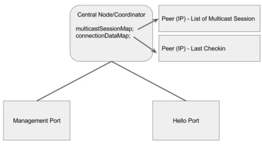
3.1.1 Central Node 36
3.1.2 Peer 40
3.1.3 ISP Collaborative Service 42
3.1.4 Extended Central Node 43
3.1.5 Extended Peer 44
3.2 Distribution Trees Construction 45 3.2.1 Minimum-Delay Approach 46 3.2.2 Minimum-Loss Approach 48 3.3 Collaborative Methods/Approaches 54 3.3.1 Link Protection 54 3.3.2 Link Minimization 57
3.3.3 ISP Forwarder Activation 61
3.4 Overlay in multiple Autonomous Systems 64 4 t e s t i n g a n d r e s u lt s a na ly s i s 67
4.1 Technologies and Testing Platform 67
4.1.1 Development Tools 67
4.1.2 Network Emulation 70
4.1.3 Web-Application 70
4.2 Minimum-Delay 71
4.2.1 Activating the Central Node 72
4.2.2 Activating the Collaborative Service 73
4.2.3 Activating the Sender (Node N8) 73
4.2.4 Activating a Receiver (Node N7) 74
4.2.5 Activating other Receivers 75
4.2.6 Deactivating Peer N25 (10.0.22.20) 78
4.3 Minimum-Loss 79
4.3.1 Activating the Scenario 80
4.3.2 Activating Receiver N7 81 4.3.3 Activating Receiver N28 82 4.3.4 Activating Receiver N30 83 4.3.5 Activating Receiver N29 85 4.4 Protect-Link 86 4.4.1 Passive Protection 86 4.4.2 Active Protection 92 4.5 Link Minimization 97
4.5.1 Activating the Scenario 98
4.5.2 Link Minimization Procedures 98
4.6 ISP Forwarder Activation 102
4.6.1 Activating the Scenario 105
4.6.2 Forwarder Activation Step 1 - Link Minimization Procedures 105 4.6.3 Forwarder Activation Step 2 - Activating Forwarders 106
4.7 Multiple Autonomous Systems 108
4.7.2 Link Minimization Procedures and new Distribution Tree 113 5 c o n c l u s i o n s 115 5.1 Developed Work 115 5.2 Future Work 116 6 b i b l i o g r a p h y 119 a s e c o n d a r y t r e e r e p r e s e n tat i o n 123 a.1 Minimum-Delay Approach 123
Figure 2.1 Unicast vs Multicast 6 Figure 2.2 Multicast Groups Example - Part One, Extrapolated from [2] 9 Figure 2.3 Multicast Groups Example - Part Two, Extrapolated from [2] 10 Figure 2.4 API - Interface for Peers, Source: [19] 18 Figure 2.5 Flooding-Based search schema, Source: [6] 20 Figure 2.6 Random Walk search schema, Source: [6] 21 Figure 2.7 BitTorrent Architecture, Source: [19] 22 Figure 2.8 IP Multicast delivery, adapted from Source(s): [4,43,45]. 26 Figure 2.9 Application-Layer Multicast delivery, adapted from Source(s): [4,43,
45]. 27
Figure 2.10 TOMA architecture, Source: [12] 28 Figure 2.11 OMNI architecture, Source: [34] 30 Figure 2.12 Scattercast architecture, Source: [36] 32
Figure 3.1 Conceptual Architecture 36
Figure 3.2 Conceptual Central Node view 37
Figure 3.3 Distribution Tree example, Central Node’s Graph Representation 39
Figure 3.4 Conceptual Peer View 40
Figure 3.5 Conceptual Central Node, Extended 43
Figure 3.6 Conceptual Peer, Extended 45
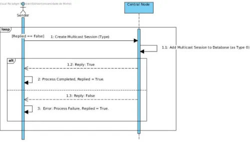
Figure 3.7 Activity Diagram - Creating a Multicast Session 46
Figure 3.8 Joining Peer Decision Example 49
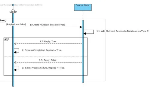
Figure 3.9 Creating a minimum-loss multicast session 50
Figure 3.10 Minimum Loss Answer Accumulator 52
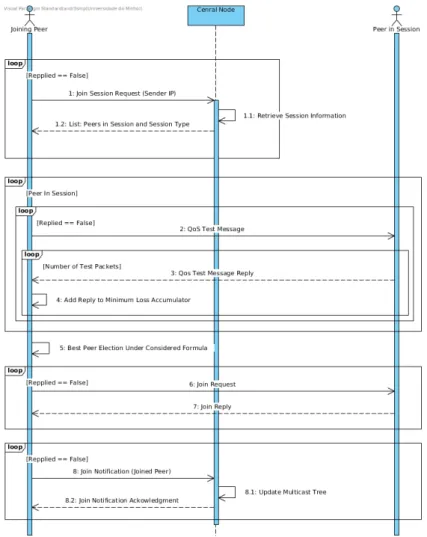
Figure 3.11 Joining a minimum-loss multicast session (Simplified) 53
Figure 3.12 Passive Link Protection 56
Figure 3.13 Complete Graph Representation In Parity Maps 58 Figure 3.14 Complete Graph Matrix Representation 59
Figure 3.15 Forwarder Placement 63
Figure 3.16 Best Match Determination Logic, N Forwarders 63 Figure 3.17 ISP Forwarder Activation Summarized Process 64 Figure 3.18 Multiple Autonomous Systems - Expanded Architecture 65
Figure 4.1 Graph Data Structures 69
Figure 4.2 Testing Network Topology 71
Figure 4.3 Activating the Central Node 73
Figure 4.4 Creating a multicast session 73
Figure 4.5 Activating Node 7 - Part 1 74
Figure 4.6 Activating Node 7 - Part 2 74
Figure 4.7 Activating Node 7 - Part 3 75
Figure 4.8 Activating Node 7 - Part 4 75
Figure 4.9 Activating Node 7 - Part 5 75
Figure 4.10 Receivers Activation, Distribution Tree Representation 76 Figure 4.11 Overlay Distribution Representation 76
Figure 4.12 Path between N8 and N30 77
Figure 4.13 Deactivating Peer N25 Logs 78
Figure 4.14 Deactivating Node N25 - Tree Representation 1 79
Figure 4.15 Updated Network Topology 80
Figure 4.16 Activating Scenario Result 81
Figure 4.17 Logging - Arrival of Peer N7. 82
Figure 4.18 Logging - Arrival of Peer N28. 83
Figure 4.19 Minimum-Loss Tests: Multicast Tree Stage 2. 83
Figure 4.20 Logging - Arrival of Peer N30. 84
Figure 4.21 Minimum-Loss Tests: Multicast Tree Stage 3. 85
Figure 4.22 Logging - Arrival of Peer N29. 85
Figure 4.23 Minimum-Loss Tests: Multicast Tree Stage 4. 86
Figure 4.24 Activating the Central Node 87
Figure 4.25 Activating the collaborative service - Part 1 87 Figure 4.26 Activating the collaborative service - Part 2 88 Figure 4.27 Logs regarding the activation of the sessions’ sender 88 Figure 4.28 Logs regarding the activation of peer N7 88
Figure 4.29 Multicast Tree Stage 1 89
Figure 4.30 Path from peer N25 to peers N7 and N8 89 Figure 4.31 Multicast Tree stage 2 - Representation 90 Figure 4.32 Passive Protection: Overlay Distribution Tree 90 Figure 4.33 Central Node’s reply to peer N26 90
Figure 4.34 Multicast Tree Stage 4 91
Figure 4.35 Passive Protection: Final Overlay Distribution Tree 91 Figure 4.36 Tree before protection (Stage 7) 93 Figure 4.37 Active Protection: Overlay Distribution Tree 93
Figure 4.38 Path between peers N29 and N30 94
Figure 4.39 Collaborative Service’s request to protect link N5-N18 94 Figure 4.40 Central Node Logs Receiving the collaborative service’s request 95
Figure 4.41 Central node identification of problematic peers 95 Figure 4.42 Peer N29 logging the removal of peer N30 from downstream list 95 Figure 4.43 Peer N30 is requested to establish new connection 95 Figure 4.44 Peer N30, paths to possible connections 96
Figure 4.45 Final multicast tree 96
Figure 4.46 Active Protection: Overlay Distribution Tree 97 Figure 4.47 Scenario activation resulting Overlay Distribution Tree 98
Figure 4.48 Scenario activation result 99
Figure 4.49 Parity Map Creation (summarized) 100
Figure 4.50 Complete Graph Matrix 100
Figure 4.51 PRIM output for MST 101
Figure 4.52 Logging - Central Node logs peer Notifications and
acknowledge-ments. 101
Figure 4.53 Final Multicast Tree. 102
Figure 4.54 Final multicast tree with demonstrated paths. 103
Figure 4.55 Adapted Network Topology 103
Figure 4.56 Scenario activation result 105
Figure 4.57 Distribution Tree Representation 106
Figure 4.58 Link Minimization result 106
Figure 4.59 Distribution Tree Representation 2 107
Figure 4.60 Forwarder Tests Report 108
Figure 4.61 Forwarder Activation result 108
Figure 4.62 Multiple Autonomous Systems Network Topology 109
Figure 4.63 Scenario activation result 111
Figure 4.64 External Graph Matrix 113
Figure 4.65 Final Distribution Tree 113
Figure 4.66 Final distribution tree - Paths 114 Figure A.1 Receivers Activation Representation 2 123 Figure A.2 Deactivating Node N25 - Tree Representation 2 123 Figure A.3 Multicast Tree Stage 4 -Representation 2 124
Table 2.1 Packet count log unicast 7
Table 2.2 Packet count log multicast 7
Table 2.3 Most common Structured and Unstructured P2P overlays,
summa-rized from source [9] 17
Table 3.1 Entities and interactions of Figure 3.1 36
Table 4.1 Link introduced data delay 72
Table 4.2 Packet Loss assumed in specific links 79
ALM Application-Layer Multicast.
ALTO Application-Layer Traffic Optimization. AS Autonomous System.
ASM Any Source Multicast. DHT Distributed Hash Table. DM Dense Mode.
DVMRP Distance Vector Multicast Routing Protocol. HTML HyperText Markup Language.
IANA Internet Assigned Numbers Authority. IETF Internet Engineering Task Force.
IGMP Internet Group Membership Protocol. IP Internet Protocol.
MSN Multicast Service Node.
MSON Multicast Service Overlay Network. OLAMP Overlay Aggregated Multicast Protocol. OMNI Overlay Multicast Network Infrastructure. P2P Peer-to-Peer.
PIM Protocol Independent Multicast. QOS Quality of Service.
RFP Reverse Path Forwarding.
RIP Routing Information Protocol. RP Rendezvous Point.
SCX Scattercast Proxy. SM Sparse Mode.
SSM Source Specific Multicast.
TOMA Two-Tier Overlay Multicast Architecture. TTL Time-To-Live.
1
I N T R O D U C T I O N1.1 i n t r o d u c t i o n a n d m o t i vat i o n
In the recent past, with the evolution the network infrastructure has seen, both in its capac-ity to deal with more and more users as well as the capabilcapac-ity to deliver data much faster than ever before, the number of devices and applications that are now generating traffic to the network has increased exponentially. Considering this growth, a necessity arises for solutions and technologies which are able to cope with the ever increasing amount of data that is introduced in the network at any given moment, particularly with applications re-lated to group communication, such solutions will have to be both efficient and scalable. In this context, the IP Multicast [1,2] technology emerges as one of those solutions. In fact, it
allows for a better exploitation of the network’s resources, taking into consideration that a given data flow may be intended for various destinations, and IP Multicast allows for that same data to be replicated only in the branching nodes within the network [3].
Even though the benefits of implementing multicast at the network level (IP multicast) would be immense, the difficulties associated with such deployment [4] have lead to the
development of new paradigms, such as Application-Layer multicast [10]. Among these
complications emerge the complexity of the protocols associated with IP Multicast as well as the lack of scalability necessary for this technology to be applied to the Internet full extent [12] where a considerable amount of multicast users/groups will have to be supported.
Also, economical and security reasons have been behind the non-deployment of multicast by Internet Service Providers.
On the other hand, Application-Layer multicast solutions are characterized by their rather easy implementation, considering its up to the application level developer to implement the system. Moreover, this kind of implementation does not result in a direct (economical) cost to the Service Providers given the fact that the management of multicast groups and data replication happens by software and not on routers, reducing the necessity for routers with increased computational capacity. However, these systems lack the network state knowledge, which leads to a scenario where the multicast implementation is not always as efficient as possible.
All the facts stated above have lead to a stagnation of IP Multicast development and to an approximation to the overlay network alternative. In this context, this thesis aims to develop and implement an overlay multicast system with an easily reconfigurable distribution tree, in order to assume different contexts of usability, and which enables interaction between the overlay system and the ISP, who knows the current state of the network. This cooperation between the multicast system and the ISP provides the tools for a better management of the network’s resources, enabling ISPs to apply different policies that better suit the network state and the kind of group communication that is being performed. This hybrid approach’s objective is to allow for a better traffic management by the ISP, while also allowing for an increased knowledge of the application level, leading to a performance improvement with regards to a more resilient and efficient overlay infrastructure.
1.2 o b j e c t i v e s
This thesis main goal is to develop an Overlay Multicast network which is adaptable to different usability contexts. This overlay network is to be easily reconfigurable in order to be able to assume different behaviours in the establishment and maintenance of the multicast distribution tree taking into account distinct approaches (e.g. minimum delay, packet loss, computation cost, etc).
In addition to the previously mentioned objective, the prototype should include collabo-ration mechanisms between the overlay network and the Internet Service Providers in order to allow the ISPs to be active participants in the definition of the overlay network, providing the tools for the ISP to ensure its best interests and objectives. Finally, in a latter stage, the aim is to devise a solution that provides the overlay network with the capacity to operate in scenarios that involve various autonomous systems.
Taking into consideration the previously mentioned objectives, a list of particular objec-tives is presented:
1. Investigation of the state of the art of the involved research areas.
2. Definition of the various components and mechanisms to develop, as well as their operating rules, mainly with regards to the construction and maintenance of the mul-ticast tree.
3. Implementation of the overlay network prototype. This implementation should repre-sent all created entities and be able to establish the mentioned communication capac-ity between the various components of the system.
4. Test of the developed prototype as well as a comprehensive analysis of the obtained results. These tests are to, as much as possible, resemble a real scenario operation.
1.3 m a i n c o n t r i b u t i o n s
This work studied, designed, developed and tested the creation of a flexible and adaptable overlay multicast network. This network, with different possible configurations in order to maximize different objectives, presents an interesting proposal to the Internet Service Providers as the platform also allows the inclusion of the ISP in the management of the overlay. As the overlay network assumes a collaborative perspective, the ISP can cooperate with the system to better manage the overlay’s traffic, and so, allowing the ISP to better implement its traffic engineering policies. This cooperative approach, which many other overlay architectures do not consider, improves the underlying topology’s resilience and allows the overlay to enjoy the ISPs good will. This is possible as they operate together, not only to improve the overlay’s performance but, more importantly even, to improve the ISP’s capacity of peacefully adapting traffic flow into the overlay. Otherwise the ISP will have to take more drastic measures to protect the network topology.
The testing stage has shown proof that the developed architecture and methodologies operate properly, showing the operational feasibility of the system. This testing has shown peers forming an overlay network independently of the collaborative service whenever no intervention was required. Furthermore, when requests arrived on the central node, by the ISP, the performed tests show the central node manipulating the distribution tree in order to accommodate the ISP’s operating commands.
1.4 t h e s i s o r g a n i z at i o n
The current thesis will be organized in six chapters, whose description follows:
• Introduction and Motivation: This chapter provided a contextualization for the work to develop, having characterized the general concept of the idea as well as the prob-lems a prototype like the one presented could solve and, most of all, the advantages in performance, scalability and security a system like this would provide.
• State of the art: This chapter will provide the theoretical premises with regards to the current state of the different technologies that will be used, in order to allow for a better understanding and definition of the various components and mechanisms that will have to be conceived and that will result in the proposed solution. In this chapter, a broad look into multicast, and particularly multicast at the network level, will be provided, as well as a more in-depth analysis of overlay peer-to-peer systems and application-layer multicast.
• Architecture and Developed System: Here, a detailed look is given on the devel-oped architecture and distribution tree construction methodologies. First, the
sys-tem’s general architecture is presented and described, namely the main entities and components, as well as the way they operate on a logical level. After this description, different approaches on the construction and maintenance of the multicast distribu-tion tree are presented, where both independent and collaborative approaches are shown and explained.
• Testing and Analysis: The testing stage shows the technologies used in the develop-ment of the present work’s prototype, as well as a variety of test cases/scenarios. Ini-tially, the development tools are presented as well as the testing platform, the CORE network emulator. After, a test case is presented for each of the operating method-ologies, showing the obtained results, as well as a critical analysis as to the system’s response to events, which are shown step-by-step.
• Conclusions: This chapter presents the conclusions extracted from this work. The developed work is summarized before presenting what could be the future work for the presented system, namely improvements to be made that would definitely be an addition to the system’s characteristics and extend its range of operability.
2
S TAT E O F T H E A R TThis chapter will provide an analysis of the fundamental concepts regarding the technolo-gies important to this thesis. First and foremost, an explanation on the way IP multicast operates in order to provide an idea of why this way of implementing multicast has not seen a great evolution or a great interest by the Service Providers, Section2.1. Having presented the fundamental concept of multicast and IP Multicast, the focus will shift to peer-to-peer overlay systems, in order to introduce a different paradigm to the way of distributing data, Section2.2. Finally, an investigation of application-layer multicast systems is presented, in order to gain the necessary sensibility to understand the current ways of forming multicast distribution trees so as to determine proper paths for data flows, Section 2.3.
2.1 i p m u lt i c a s t
This section will detail IP Multicast, the way multicast distribution trees are formed as well as the way they are maintained [2]. However, before specifying IP Multicast, an explanation
will be provided on the Multicast paradigm itself, mainly its principles and objectives.
2.1.1 Multicast Fundamentals
Multicast is a technology developed with a very important purpose in mind, which is to reduce, as much as possible, the amount of data generated into the network. In a world where group communication is increasingly more important (be it via video-conferencing, stock data, gaming and so on) [3], the amount of data that applications are introducing in
the network is immense. Typically, should a device, for some reason, need to send any data to another device, a unicast connection is established, meaning that packets go from one source to one destination. This makes perfect sense, given the fact that such source is trying to reach a specific destination. However, considering the case where a given source is trying to send the same exact information to two (or more) destinations, what should happen? In a typical scenario, the sender creates as many datagrams as there are destinations, a unicast connection is established between the sender and each of the receivers, and all datagrams
are sent to and through the network. Multicast removes this necessity on the sender by introducing a new strategy in data-delivery, the sender now simply creates one datagram with one destination group and sends it to the network, and this single datagram is, then, replicated only in branching nodes and delivered to all recipients in that group. Figure2.1 illustrates this exact paradigm difference.
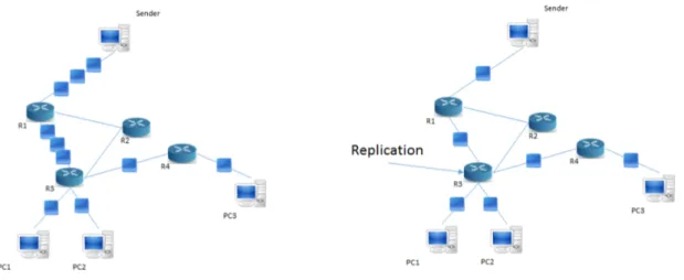
Figure 2.1.: Unicast vs Multicast
Analyzing Figure 2.1, on the left side, a given sender is attempting to send the same information to PCs 1, 2 and 3. As unicast connections are in place, the sender creates three copies of the same packet, one for each destination, and sends them into the network, through router R1. This router, then, forwards the data to router R3 who delivers one copy to receivers PC1 and PC2 each. Router R3 also forwards one copy of the data to router R4, with final delivery to PC3 taking place. Alternatively, on the right side of Figure 2.1, where multicast is being used, the employed logic is quite different as the sender sends only one copy of the data into the network, with the multicast group’s address. So, router R1 forwards the only copy of data it received to router R3. This router, knows receivers PC1 and PC2 are directly connected to it, replicates the packet twice, one for each receiver, and forwards the packet to router R4, who, once more, makes delivery to PC3, performing no replication.
Tables2.1and2.2, represent the number of datagram packets that are in the network at any given time. Considering a scenario where receivers PC1, PC2 and PC3 are not in a multicast session/group, the sender needs to create three new datagram packets and these datagrams need to travel, separately, through the network until they reach their destination, which does not happen in a case where receivers PC1, PC2 and PC3 are in a multicast group and the sender simply needs to create one single datagram and send it to the group. When comparing Tables2.1and2.2an immediate conclusion is established, which is that multicast
Sender Receiver Number of Packets Sender Router R1 3 Router R1 Router R3 3 Router R3 PC1 1 Router R3 PC2 1 Router R3 Router R4 1 Router R4 PC3 1
Table 2.1.: Packet count log unicast
Sender Receiver Number of Packets
Sender Router R1 1 Router R1 Router R3 1 Router R3 PC1 1 Router R3 PC2 1 Router R3 Router R4 1 Router R4 PC3 1
Table 2.2.: Packet count log multicast
reduces the amount of data in the network structure and also reduces the amount of work the sender needs to perform, dividing the work throughout the network infrastructure itself.
2.1.2 IP Multicast
Having seen a very broad description regarding multicast’s modus operandi, it’s important to take a more detailed approach, particularly on a network level, IP Multicast. As stated in Section2.1.1, generally normal IP packets are sent, via unicast connection, from a single source to a single recipient, where said datagram packets are delivered to the destination according to a predetermined forwarding table. Taking into consideration that the number of established connections equals the number of receivers, and also that the number of (equal) datagram packets the source will have to create also equals the number of recipients, it is clear that the efficiency of this process is not the best, given the current growth on the (ever increasing) number of applications that stream audio and video [14]. Also, in order
to be able to create a datagram for each receiver, the source would need to maintain an updated list of all receivers, which is unfeasible, taking into account the processing cost of such a task. More importantly even, on a network level, what this means is that a number of copies of the same data would be introduced into the network and would flow through the same links, which means a huge increase of bandwidth usage and also costs due to
the fact that the network itself would have to be able to deal with such a huge data flow increase.
Thus far, it has been established multicast provides the source with a way to deliver data to all destinations sending only a single copy of data which routers then forward, constantly duplicating said data only in branching nodes, meaning, where paths to different destinations vary. However, how do these routers know where to send this data to? Well, multicast groups identify a set of recipients which are interested in data being streamed by a particular source [2]. Moreover, these multicast groups have an (attributed) IP address
and the source simply sends data to this IP address which is then forwarded to all members of the multicast group.
Taking into consideration the concept of multicast groups, it is important to understand how these procedures are actually put in place, mainly with regards to the job each entity has to perform. Clearly there are different approaches each entity takes when interacting with these groups:
• The source sends only one datagram packet into the network, whose destination ad-dress is the IP adad-dress of the actual multicast group, not having to consider how this data is actually delivered to all destinations;
• Users that wish to receive the data being streamed, need to join the multicast group the sender is addressing. This is achieved through a join request to a multicast router in the user’s local interface, using an Internet Group Membership Protocol (IGMP). • Multicast routers are in constant communication between themselves, and implement
Multicast Routing Protocols (such as PIM-SM [15] and PIM-DM [16]) so as to
guaran-tee not only that all hosts that have joined each group receive their wanted information but also that no bandwidth is wasted sending data to multicast routers that do not contain any receivers in the designated multicast group.
It is clear that all this information regarding multicast groups, mainly which multicast routers have group members appended to themselves, needs to somehow be maintained in an updated manner. So, multicast routing protocols constantly calculate a multicast distribution tree in order to ensure that traffic is not sent to unnecessary networks (networks that have no members in the multicast group) and to minimize the number of copies of the same data introduced into the same network link.
Let’s take the small example in Figure 2.2 into consideration, assuming the Routing In-formation Protocol (RIP) is the protocol being used in the computation of the respective forwarding tables.
In this scenario, PC1, PC2, PC4, PC7 and PC8 are members of the multicast group the source is sending to. And so, a few conclusions can be drawn, such as:
Figure 2.2.: Multicast Groups Example - Part One, Extrapolated from [2] • The source sends only one datagram to router R1;
• Router R1 duplicates the datagram (it is a branching node!) and sends one copy to router R2 and another to router R5;
• Router R2 forwards the data to router R3 which then forwards it to router R10; • Router R10 delivers the datagram to PC8, and stops;
• Having received the datagram from router R1, router R5 duplicates it and delivers one copy to router R4 and another to router R7;
• Router R4 duplicates the datagram once more, and delivers a copy to PC1 and another to PC2;
• Router R7 performs another copy of the same datagram and delivers one copy to router R8 and another directly to PC4;
• Router R8 forwards the data to router R9, not performing any copies; • Router R9 delivers the data to PC7 directly.
Figure2.3 illustrates the described process, highlighting copies performed by the multi-cast routers, i.e., highlighting the branching nodes.
However, what would happen should PC3 now join the same multicast group? Would the number of datagrams in the network change? No. Simply, router R7 would just perform yet another copy upon receiving data from the multicast group in question, and deliver that copy directly to PC3, which is in the same local network as PC4.
Figure 2.3.: Multicast Groups Example - Part Two, Extrapolated from [2]
2.1.3 Multicast Groups
It has been stated that the multicast source creates only one datagram packet and addresses it to the multicast group it is streaming to, and data is then carried out to all corresponding members. However, no description has yet been given as to the way these multicast groups are created or to the way receivers discover them.
Well, before a given source can start streaming (sending) data to a group or even a receiver starts receiving data from said source (or list of sources) it must first determine the address of said multicast group. The Internet Assigned Numbers Authority (IANA) [17] is
the entity responsible for assigning multicast group addresses to pre-established protocols and services. Then, network administrators offer other addresses in order for hosts to be able to request and use them, mainly at an application level.
Having established how multicast groups are assigned for a given time to a host (in this case, a sender), it is now important to mention that there are different types of hosts, receivers for instance. So, when joining a multicast group, hosts can elect to receive data sent to the group from multiple sources (ASM - Any Source Multicast) or from a specific source (SSM - Source Specific Multicast).
Any Source Multicast
Taking into consideration a scenario where a given host wishes to join a multicast group and receive data from all sources within that group, this host needs only to specify the IP address of the multicast group in question (*,G), and begins receiving data from any host acting as a source. However, even though the process to enter the multicast group and start receiving data is much simplified, it comes with a few drawbacks:
• Security - The ASM model is more susceptible to denial-of-service attacks, due to the fact that sources are not controlled and may keep flooding the network with an excessive amount of data;
• Interdomain Multicast Routing - In this scenario, and remembering that there can be a multitude of sources, it may become harder to deal with the multicast tree formation and maintenance. This comes as a result from the fact that the mechanism for source discovery will necessarily have to be much more complex.
The ASM model is quite used for applications where the number of sources is not con-trolled, predictable, or keeps changing. Applications such as video-conferencing for in-stance.
Source Specific Multicast
The Source Specific Multicast scenario presents quite a number of differences in the way it operates when compared with ASM. When entering a multicast group, a given host must not only specify the IP address of the multicast group itself but also the IP address of the source it wishes to receive data from (S,G), which, obviously, adds another layer of complexity (and necessary knowledge) on the part of the joining member. Now, this added complexity also comes with a number of advantages [18]:
• Elimination of cross delivery of traffic when more than one source simultaneously use the same source specific destination address;
• Address allocation becomes much simpler since the multicast group address is local to the source, meaning no global allocation mechanism is required;
It becomes clear SSM is more appropriate for scenarios where it is predicted that the number if sources will be quite small, and the sources are unchanging. Consider the exam-ple of audio and video broadcasting where, despite the number of receivers, the sources typically remain the same.
2.1.4 Multicast Routing Protocols
Multicast routers need to exchange information between themselves, mainly regarding their directly connected neighbours, in order to be able to join and leave multicast trees, tak-ing into consideration the multicast groups that hosts appended to them are connected to. These information exchanges are performed using a multicast routing protocol, of which there are a few. However, the most used protocols in this area are Protocol Independent
Multicast Sparse Mode (PIM-SM), Protocol Independent Multicast Dense Mode (PIM-DM) and Distance Vector Multicast Routing Protocol (DVMRP).
The mentioned communication between multicast routers, is used in order not only to allow multicast routers to join and leave multicast groups, but also in the creation and maintenance of multicast trees so that, once a multicast tree has been constructed, data is forwarded down the multicast tree, replicated when the path to the different recipients diverges.
So, knowing multicast trees are constructed using multicast routing protocols, it is impor-tant to understand the paradigm differences that make these various protocols diverge. The multicast tree is constructed according to three main factors: i) The routing protocol used (opt-in or opt-out); ii) Their tree construction and maintenance mechanism (source-based or shared-tree); iii) Their upstream router determination.
OPT-In vs OPT-Out Protocols
Protocol Independent Multicast Sparse Mode (which will be further detailed) is an opt-in protocol. Opt-opt-in (or sparse) protocols are used opt-in scenarios where the receivers are considered to be sparsely distributed throughout the network. This means that, if routers were to be receive data they did not ask for, many subnets would be receiving a lot of multicast packets [2]. Well, in an opt-in protocol, routers are inserted in the multicast tree
solely when they indicate interest in a determined data flow, otherwise, are kept out of the multicast tree. It is important to state that, in this approach, routers send a join message to the upstream router only when one host, that is appended to said router, asks to join the multicast group.
Whereas with opt-in protocols, routers have to express their will to be included in the multicast tree, in the case with opt-out protocols, such as Protocol Independent Multicast Dense Mode and Distance Vector Multicast Routing Protocol, the default scenario is that every router in the network is interested in receiving the multicast data being streamed, and so, this data is forwarded to all routers. The logic being that, if a router does not have any host interested in said data, it will simply inform the upstream router of its wish to remove itself from the multicast tree, which is done via prune request message.
Source-Based vs Shared Tree Protocols
Multicast trees can be constructed in various manners, depending on the chosen multicast routing protocol. There are two types of trees used by the main multicast routing protocols, they can be source based or shared based.
In the case of source-based tree protocols, an independent multicast tree is built for each source (each sender) in the group, leading to a multitude of different trees. Each one of these trees finds its root in the router to which such source is connected to. PIM-DM and
DVMRP are source-based tree protocols, which means, routers wishing to join a particular multicast group must specify both the IP Address of the group and the source they are interested in, a request that is made to the upstream router.
Shared tree based protocols, present a more complex system when it comes to tree gen-eration. This is due to the fact that, instead of creating a new multicast tree for each source, only one multicast tree is generated, possibly more complex, and all sources in the multi-cast group use the same multimulti-cast tree to forward their data. This single tree is rooted at an elected node (the Rendezvous Point (RP) in PIM). However, in a scenario where there is only one root and multiple sources are enabled to stream data into the multicast group, in order to ensure every host receives the desired data, it is fundamental that all data be distributed at the source of the tree. This is performed by sending the data to the root of the tree at which point it is forwarded through the appropriate paths in the network
Finally, it is important to highlight that shared tree protocols are more appropriate than source-based protocols when there are more potential sources in the multicast group, how-ever, they require a more inefficient system due to the fact that, before being forwarded to all hosts, datagrams must be delivered to the root of the multicast tree.
Determining the Upstream Router
It has been stated that, when joining a multicast group, routers must determine their up-stream multicast router. This requires reverse path forwarding (RFP) look-ups, which can happen in order to determine the address of either the source of data or the root of a shared tree, depending on the model being used.
Multicast routers use the same interface for their join and prune messages (or any con-trol packet) as well as content, i.e., actual data being sent. To perform their reverse path forwarding look-up operations, most protocols use their own mechanisms to exchange the necessary routing information (such as DVMRP) while others, such as PIM, use a Multicast Routing Information Protocol populated by a third-party source.
2.1.5 Protocol Independent Multicast (PIM)
Protocol Independent Multicast is a collection of multicast routing protocols, each opti-mized for a different environment. There are two main protocols, previously mentioned in this document, PIM Sparse Mode and PIM Dense Mode. All these protocols share a common control message format, messages which are sent either to the multicast group including the PIM routers, or as unicast datagrams to specific locations.
In this section a brief description of the two main versions of the protocol will be pre-sented, focusing particularly on the advantages and disadvantages of each protocol.
Protocol Independent Multicast Sparse Mode
PIM Sparse Mode is an opt-in multicast routing protocol, once more, meaning that routers must explicitly notify their upstream neighbours of their interest in a particular group and source. This notification is performed via PIM Join and Prune messages to join and leave the multicast routing tree. These PIM join messages have to keep being re-transmitted as PIM-SM is a soft-state protocol, which means, all state is timed-out after a predetermined time interval.
By default, PIM-SM uses shared trees, with the trees for each group rooted at a router called the Rendezvous Point (RP). As stated, data is sent from a source to the RP in PIM con-trol messages using unicast connections. If necessary, PIM-SM can also fallback to source-based trees to avoid the encapsulation process required in order to send the message/data to the RP, among other reasons.
The advantages of PIM Sparse Mode far outweigh the disadvantages, which is why PIM-SM is considered to be one of the best solutions to the multicast paradigm, its advantages are:
• Like the name suggests, PIM is protocol-independent, meaning it can operate regard-less of the unicast protocol that is implemented in the network;
• It scales well across bigger networks;
• Sparse Mode allows for information to be only contained at routers belonging to the multicast tree;
• It supports both SSM and ASM.
Even though the number of disadvantages is less considerable, it is important to under-stand that in shared trees, the process of encapsulation and decapsulation that is performed between the source and the Rendezvous-Point can become quite inefficient, and it may be required a number of times.
Protocol Independent Multicast Dense Mode
PIM Dense Mode (PIM-DM) is an opt-out multicast routing protocol. It is quite less com-mon than PIM-SM due to the fact that it is most efficient in smaller domains, not scaling well when the network starts expanding. The fact that PIM-DM is an opt-out protocol, means that any router that joins the multicast group, is immediately added to the multicast distribution tree and, therefore, immediately starts receiving data.
Once more, PIM-DM, unlike PIM-SM, uses source-based trees in order to calculate its most efficient data forwarding scheme. There is, however, a particular rule about this protocol, which is that it does not have a mechanism in which routers explicitly join the
multicast tree, instead, they are presumed as branches of the multicast tree and required to send Prune messages in order to be removed from it.
To summarize the advantages of PIM-DM, remembering this is a smaller-scale protocol: • It is a very efficient protocol when receivers are densely distributed in the network; • It is protocol-independent;
• It supports SSM and ASM;
• It does not use Rendezvous points which makes it lighter and easier to implement.
2.2 ov e r l ay p e e r-to-peer (p2p) systems
In the previous section, 2.1.2, regarding IP Multicast, even though, performance wise, the implementation of multicast at the network level provides a performance other solutions can not match, it is clear that this implementation is also quite limited. This has to do with various factors, such as the high amount of processing power IP Multicast would require from the multicast routers, for instance. Also, in a scenario contemplating any source multicast, denial of service attacks are clearly extremely hard to avoid, so security is also a limitation to the deployment.
In this context, other solutions came to light, further away from the network and closer to the application layer, most of which based on overlay p2p paradigms.
This section will present an overview of some peer-to-peer paradigm fundamentals, fo-cusing on the solutions this approach provides. Then, different architectures will be con-templated, such as Structured and Unstructured P2P systems and finally an observation regarding the most used systems in a structured architecture as well as a fundamentals look on the basic search mechanism for unstructured P2P systems.
2.2.1 Overlay P2P Concepts and Applications
Peer-to-Peer overlay systems are distributed computer architectures, built of top of an ex-isting network [6, 20], designed with multiple objectives in mind, such as sharing data,
resources, etc, by direct exchange. This approach disregards a centralized server in the network coordination. In this context, without any hierarchical organization, the intercon-nected computers, named Peers, form self organizing overlay networks, operating on top of the Internet Protocol itself.
The concept of having independent peers forming and managing their own network comes with a number of advantages. The cooperative manner with which peers operate and share their resources, allows for a level of scalability and growth that, otherwise, would
be very hard to achieve. Peers perform a wide variety of tasks in a system like this, needing to act both as clients and servers at the same time while also participating in the process of searching and delivering content that they neither possess nor want, but it may be the case that, in the overlay, the path from source to destination includes those particular peers. Another very important characteristic of this kind of system has to do with its high fault tolerance and low vulnerability, namely its capacity to deal with peer failures. This is possible due to the fact that every peer operates independently, and, at most, what can happen is that certain content may disappear with the failing peer (in case only it should have the desired content). To this point, an attack on the network, would have to be of massive scale, and reach a large percentage of the overlay network, at the same time. Also, as peers operate independently, and this structure is peer-based, it makes for an inherently easier deployment when compared with a system that controls data flow on a network level.
Certain characteristics may vary in the construction of the overlay network structure, in order to optimize (namely with distinct routing and maintenance algorithms) it to achieve different levels of performance considering different goals, such as:
• Data-Sharing [23,24]: Data storage and retrieval are one of the highest contributors to
peer to peer systems development. Peers containing information spread it throughout querying peers (a logic that will be explained further in this document);
• Bandwidth-Sharing and Telephony[7,25]: Very similar to data-sharing, but optimized
for efficient streaming of real-time data throughout the network as the ability to shuf-fle information via different paths in the network becomes of major importance so as not to flood a specific path, and in order to take advantage of less occupied routes; • CPU-Sharing [26, 27]: Peers can combine their machines, mainly during down-time,
and perform data mining with applications being developed mainly for scientific re-search.
2.2.2 Architecture
As peer to peer systems may serve different purposes by having different applications and as they can be optimized to perform better under specific circumstances, it makes sense to think that this kind of optimization is to be reflected in the overlay’s structure. As stated in the previous section, peers forming the overlay network operate independently but also, each peer has its own set of responsibilities, requiring them to perform a wide variety of tasks within the system, namely acting as both clients and servers to the overlay structure, performing their own direct connections to other peers (directly connected peers are called neighbours) and participating in search and content transmission efforts.
Structured Unstructured Chord Freenet CAN Gnutella Pastry FastTrack Tapestry BitTorrent Kademlia UMM
Table 2.3.: Most common Structured and Unstructured P2P overlays, summarized from source [9]
Taking into consideration the different operating scenarios an overlay network can present, as well as peer obligations within the overlay, P2P systems are usually classified into two categories: structured and unstructured. Now, conceptually, each peer maintains its own collection of information/data to share, and, upon the arrival of a request for data, it be-gins transmitting it. Moreover, to perform a request, peers make query requests, making them the querying peer. When a peer receives a query, it checks its own data collection to see if it may act as the source for the desired information, and if so, begins transmitting, otherwise, forwards the request through its neighbours until either a peer with the desired data is found or a predetermined number of max hops is achieved and the search process is stopped. However, this process is not equivalent in all systems, which operate differently, with the most common structured and unstructured peer to peer overlays being presented in Table 2.3.
Structured P2P Overlay Networks
Structured p2p overlay networks offer a scenario where the network topology is controlled, and content is spread throughout strategic locations in order to maximize the search queries performance [19], instead of data simply being placed randomly throughout the network
itself. The way this placement is performed, is according to an hash function that couples data-keys with data-objects. With this relationship established, a distributed hash table (DHT) is used to route key-based queries efficiently to the peers that strategically hold the data to retrieve. This concept ensures access to the desired data within a bounded number of hops from querying peer to the peer that holds the data.
Even though the presented ideology behind DHT-based systems is the same, which is to maximize network efficiency when it comes to querying peers, different DHT-based sys-tems present different organization schemes for data objects and key space routing strate-gies. Despite this fact, DHT-based systems are expected to ensure the location of data ob-jects happens, on average, with a Olog(N) efficiency, considering a number of hops metric and N as the number of peers in the actual overlay.
Despite the fact that, theoretically, the concept of DHT-based systems presents itself as an optimal solution with regards to querying within the overlay peers, it may also produce
an outcome where search performance is highly affected, taking into account performance searches may lead to choking points as all searches are directed to the same entity, adding inherent latency to the process. Figure 2.4 provides a visual representation of the API Interface such systems use.
Figure 2.4.: API - Interface for Peers, Source: [19]
r o u t i n g Routing in structured overlay networks is widely different from unstructured overlays. The way queries conceptually operate has been very briefly mentioned in Section 2.2.2. However, it becomes clear that, as more and more peers join the system, the number of messages that need be exchanged increases exponentially, which will lead the physical network to reach its capacity, making the system non-scalable.
To deal with the presented problem, routing in structured overlays takes a different, more elegant approach, despite requiring more logistical work. Peers, on arrival, are attributed a unique identifier, which allows for each exchanged message to have a destination identifier. Each peer, sends/forwards this message solely to one neighbour in order not to flood the network. The selected peer is the next hop neighbour so as to minimize the number of hops from source to destination. This greedy approach to routing allows for a better management of the physical network’s resources, as the number of exchanged messages is quite smaller.
t h e na p s t e r m o d e l Napster [19, 21, 22] idealized an architecture for a peer-to-peer
file-sharing system based on a centralized file search mechanism. File distribution changed from a paradigm where a central service was a single source of data to a scenario where popular content can be distributed by peers who have the searched content. A p2p file-sharing system such as this, presents a self-scaling solution as more and more peers join the system, taking into account that a peer who retrieves some desired content then becomes a source of the same content, increasing the download capacity, meaning, theoretically, that
a higher number of peers intent on getting the same content, make for a higher download speed as different hosts get their files and become instant sources.
This self-scaling objective is achieved via a centralized search facility to which every peer contributes. As a part of the overlay structure, every peer provides a list of content it possesses and, therefore, is able to distribute. With a list from each peer, this search system is able to establish a connection between content and network placement and, therefore, provide the querying peer with the identity of the peer it will download the requested content from. Obviously, this centralized search also creates a single point of failure for the whole system as an attack on the entity responsible for handling this search makes determining the source of data impossible for querying peers. Also, an unexpected and immediate growth in the number of querying peers would result in a system overload.
pa s t r y Pastry [9] implements a DHT, similar to Chord [8, 28], to perform its network
routing duties. Keys and nodeIds are stored sparsely throughout a number of selected hosts, as it is a self-organizing and fully decentralized system. Each pastry node maintains a set of neighbour nodes in its nodeId space, in order to locate the destination in each routing hop as well as to protect the network and provide it with a fault-tolerance system [5] by maintaining replicas of data items so peer failures may be dealt with.
Unstructured P2P Overlay Networks
An unstructured p2p system is built upon a different paradigm when compared to a struc-tured scenario. In this case, there are no constraints on the relations between different nodes, and, as such, the overlay graph does not have a particular structure, meaning, con-tent may not (and most likely is not) be distributed in the most efficient manner as peers connect to other peers randomly and there is no relation between the placement of the data objects with the network topology [20]. This leads to an approach where peers have limited
(or even none) information on data objects stored by other peers, which results in a more complex search mechanism, as follows.
u n s t r u c t u r e d s e a r c h s c h e m e s Taking into consideration that, in an unstructured scenario, peer connections happen randomly and no central table of contents exists connect-ing peer identities with content they hold, searchconnect-ing in unstructured networks, for instance, is performed by flooding the network with a given query for content. Each peer visited will evaluate the query locally on its own content [19] and, should it have the desired data, reply
as such. Otherwise, when a peer does not contain the content to retrieve, it forwards the query through its direct neighbours, meaning, the peers it has an established connection with.
Unstructured p2p networks are easier to implement when compared with structured scenarios and result in a much lower running cost as there is no need for a highly capable computational entity to reply to all search queries. However, as the number of participating peers grows, the number of exchanged messages grows with it. Even though this leads to a more resilient system as an attack would have to be equal to the scale of the network (if one peer fails, only its content is lost, all other peers remain accessible), this type of search, to the network itself, is quite expensive.
Flooding-Based Search In an unstructured p2p system, where content is not indexed in any way, the most basic search process is to flood [20] the network with a given query until
the peer that contains the desired content is found. Flooding is performed by each peer forwarding the query to all neighbours. This makes up for a search system that can not grow with the network as the number of messages eventually gets too excessive. To stop the infinite growth on the number of messages exchanged, as would be the case in a pure flooding approach, a time-to-live is attached to the message in order to specify a maximum number of hops a message can perform. Figure2.5provides a visual representation on the Flooding-based search model.
Figure 2.5.: Flooding-Based search schema, Source: [6]
Routing Indices based Search Routing Indices are not a necessarily different approach to a flood based search, they simply represent a more direct path to the peer that contains the searched content. Every peer, besides providing content it contains, also keeps a (rather small) index that stores the direction the query message should take so as to discover the intended data. This does not change the overlay’s structuring system as content is still kept in each peer and is not organized in any particular way, simply nodes are contemplated with a higher knowledge of data placement within the network.
Random Walk A Random walk through the network graph comes as an optimization to the search process [29]. The previously regarded search schemes for unstructured overlay
networks, contemplated a search system that had every peer, upon receiving a request/-query, check its own data structure and, should it not have the desired content, forward that request to all its neighbouring peers, most likely resulting in many duplicated requests. This comes at a cost to the physical network itself, as it is flooded with excessive requests, and the search process would only stop in case content was found or every message’s Time-To-Live (TTL) was achieved.
The random walk search process has a slightly different approach. To contain the number of requests sent into the network, each peer forwards the received request, if necessary, to (only) one of its neighbours, chosen randomly. With this scenario, while it is assured that the network will not be flooded as only one copy of the request is in the network at any given time, the delay in delivery becomes unacceptable as there are no guarantees that the request is traveling in the right direction along the network. Figure 2.6 provides a visual representation on the Random Walk search model.
Figure 2.6.: Random Walk search schema, Source: [6]
b i t t o r r e n t BitTorrent is widely known and one of the most popular P2P file sharing systems [9], having millions of users active at any given time. While heavily centralized, as
it contemplates a central node/manager or tracker, it is considered to form an unstructured overlay network as peer connections do not follow any specific rules.
As far as the system’s architecture, represented in Figure 2.7, it contemplates a central node, or tracker, which will manage the way downloads are performed. A .torrent file is downloaded, containing information of the data to download like file name, locations, etc [19]. The tracker keeps a record of all peers that have the requested file and the
download-ing peers connect themselves to those. As files are split in parts, any downloaddownload-ing peer can be receiving data from many sources and can also act as the source for the data it has already downloaded.
Figure 2.7.: BitTorrent Architecture, Source: [19]
A very interesting concept is the fact that bitTorrent, in order to maintain a level of fairness in the system, implements an upload-download direct connection, as peers with high upload speed will also probably have an high download speed and the download speed will be lesser should the peer have low upload capacity. So, the more you share the more you get, which can also be unfair in some ways, so, to limit peer download rate distinctions, bitTorrent also implements a chocking algorithm to, temporarily limit peers from uploading, in order to maintain a consistent download rate throughout the whole network.
2.2.3 Consequences/Problems and Challenges
Having presented the reasons that lead to the existence of P2P systems and why they rose to such a scale, it is important to understand the additional consequences of their use.
In the remainder of this segment, a small overview will be given on the resilience of overlay networks to attacks and also on measurements to stop those attacks. Overlay main-tenance and P2P-ISP collaboration issues will also be addressed.
Attacks and Vulnerabilities
The fact that, in p2p systems, peers operate independently, as mentioned, acts a huge amplifier for scalability but also provides a high level of resilience to the system, as the effect of a failing node does not represent a big problem to the network (only in the case where the failing peer was the sole carrier of specific data, in which case it may be a problem to other peers but not to the network) and an attack would have to be in large scale, affecting as many peers as possible in order for the network to be seriously harmed.
Despite the network’s high level of resilience, attack security is still very much an issue and source of vulnerability as most current overlays are not secure, and malicious nodes can
easily insert themselves into the network and obstruct correct data delivery throughout the overlay and, in some cases, actually provide other peers with wrong (unwanted) messages. Typically good nodes can also be compromised and begin misrouting, corrupting or even dropping messages. When a good node is compromised, another major concern has to do with the information it is/was sourcing, as it may be deleted from the system or replaced with another under the same name, thus beginning a flow of corrupted data.
To the previous problems, security proposals come mainly in the form of secure routing, table maintenance and message forwarding [8]. Approaches that many systems are yet to
adapt and that need careful attention when electing a system’s structure, architecture and operating procedures.
Overlay Maintenance
Overlay networks, due to their characteristics and usability, are inherently highly dynamic and changing systems. High churn (churn regards the entrances and departures from the overlay), for instance, is a defining trait of such systems. Moreover, peers do not usually no-tify other peers of their departure, normally leaving the system abruptly or even dropping their connection and establishing a new one. To this point, the directly connected peers often are not aware of their neighbour’s departure for quite some time and so, keeping an updated routing-table becomes a harder task.
To the presented point, overlay maintenance comes with significant importance in main-taining this type of flexible and adaptable network, as it is ever-changing. So, two main approaches have been deployed [6]:
• Proactive Maintenance: Peers periodically run updates to their own routing tables with regards to the topology in place. As an example, Chord periodically runs what is called a stabilization protocol to ensure peers are linked to other in increasing distance;
• Reactive Maintenance: In this kind of approach, peers react immediately to other peers failures or departures. Missing entries (due to the leaving peer) are replaced with new ones by sending connection signals to other established peers. Peer detec-tion happens by i) Probing: Peers continuously run a ping-response protocol with each neighbour; ii) Usage: When a given peer messages another but no response arrives within a specif time-interval, that peer is considered to have failed.
P2P-ISP Collaboration
P2P overlay networks were developed with an intent to be used as a content distribution system where peers represent both the source and clients of data. This means a given peer is available to distribute a particular set of data upon request. However, P2P overlay systems
are formed on top of the Internet Routing architecture [38] with little (if any) knowledge of
the underlying network structure.
Even though P2P systems may represent a source of revenue to the Internet Service Providers as users upgrade their internet service plan, they are also an enormous traffic engineering problem due to the fact that the amount of traffic inserted into the network is very high and, a lot of times, the routing scheme is implemented independently by the overlay structure and does not consider Internet Routing or the network topology [10]. So
peers can not be used strategically throughout the network in order to reduce, as much as possible, not only the number of packets in the network but also, the length of the path datagrams take from source to destination.
A scenario to be considered is where peers A and B may be in the same autonomous system (or the same ISP) and peer C may be in another, however, as far as the overlay structure is concerned, peer A may be closer to peer C and may chose to exchange data with peer C. This means traffic would be crossing network bounds unnecessarily, increasing the operating cost to both Service Providers involved. Even worse, most bottlenecks in the Internet are assumed to be either in the access network or in links between ISPs [38].
In this context, it is important to provide both the overlay system and the Internet Service Provider with a way to collaborate in order to, at the same time, improve the performance of the p2p system and also allow the ISP to perform traffic engineering as it sees fit. IETF ALTO [46], created in 2008, is a IETF Working Group with this strategy in mind. The
concept is to provide the application level with information that only the Internet Service Provider is capable of knowing, by way of a topology graph, and so, enabling the overlay structure to perform a mode sensible routing system, increasing the system’s performance and decreasing the operating cost to the Internet Service Provider. With such a system, the ISP can use this mechanism to better manage the overlay traffic in the network by directing data along the fastest path possible, by avoiding possibly congested links, or by way of other strategy adopted by the ISP. Some additional research work examples, also involving collaborative efforts, between p2p application level and ISPs can be also found in [30,31,32].
2.3 a p p l i c at i o n-layer multicast
In the sequence of sections 2.1 and 2.2, a few conclusions can be made on the different usability of both technologies.
In Section2.1, the benefits of implementing multicast technologies become evident. Data delivery becomes much more efficient, both at the network level and for the source of content. By replicating data packets only when paths to different users diverge (branching nodes within the network) it is ensured the source no longer needs to keep a live-state on
![Figure 2 . 2 .: Multicast Groups Example - Part One, Extrapolated from [ 2 ]](https://thumb-eu.123doks.com/thumbv2/123dok_br/17270749.789126/31.892.207.732.177.456/figure-multicast-groups-example-extrapolated.webp)
![Figure 2 . 3 .: Multicast Groups Example - Part Two, Extrapolated from [ 2 ]](https://thumb-eu.123doks.com/thumbv2/123dok_br/17270749.789126/32.892.205.742.160.442/figure-multicast-groups-example-extrapolated.webp)
![Figure 2 . 12 .: Scattercast architecture, Source: [ 36 ]](https://thumb-eu.123doks.com/thumbv2/123dok_br/17270749.789126/54.892.280.662.162.503/figure-scattercast-architecture-source.webp)