Measurement of Residual Stresses in Welded Joints by DCP Method
Henrique Jun Sugaharaa, Paternak Souza Barrosa, Leonardo Gadelha Tumajan Costa de Meloa , Israel
Lira Gonçalvesa, Tiago Leite Rolima, Yogendra Prasad Yadavaa, Ricardo Artur Sanguinetti Ferreiraa*
Received: October 10, 2017; Revised: May 09, 2018; Accepted: May 16, 2018
Residual stresses on welded joints have been studied by several methods. In this present work, residual stresses was measured by a novel methodology under development named Displacement of Coordinated Points (DCP). To evaluate anisotropy effects in steel plates, two directions of the weld bead were considered: Welding was performed in both parallel and transversal direction of rolled steel plate ASTM A131 grade AH36.The experiments showed higher values of the residual stress in the transversal direction of the lamination when compared with the longitudinal direction, evidencing the anisotropy effect of the material. It was also observed that the increasing in heat input induces higher residual stress.
Keywords: residual stresses, displacement of coordinate points, anisotropy.
*e-mail: [email protected]
1. Introduction
Residual stresses have been defined as internal stresses which remain in the bodies, even at steady state, subjected to non-uniform temperature conditions and in the absence of external loads1-4. The residual stresses are macroscopic, static quantities which values range from zero up to the yield point of the material.
In all welding processes, residual stresses is a consequence of high temperature gradients, followed by rapid cooling rates which results in a complex stresses distribution.
Usually in big structures as in shipyards, the fabrication process is modular, where each module is fabricated and then assembled. Normally, welding processes are used to fabricate each module. When residual stresses are not considered, specially when welding involves restrictions, the stresses values tend to intensify causing distortions, resulting in dimensional tolerance issue, making assembly difficult and raising the costs due to rework. All these problems can be avoided by preliminary studies that would allow to understand the phenomenology.
To understand the generating mechanisms of residual stresses and to predict their values in naval panels or other structural element, theoretical studies are necessarily based on computational models. The mathematical complexity of the models due to simultaneous coupling of three effects (thermal / mechanical / metallurgical) requires validation through experimental processes5. For this reason, this theoretical / experimental methodology was created to allow the validation of models in which the same welded test plate is used, by comparing the experimental values to the obtained values by computational modeling. The major advantage of DCP is the low cost methodology when compared to others.
These residual stresses fields produced by welding processes can be either tractive or compressive. Generally, they are triaxial and vary from point to point, mainly due to the thermal gradients and the complexity of the joint geometries. In practice, residual stresses are quantities commonly measured in the two major directions that act on the surface. Determination of the residual stresses (RS) in welded joints have been performed in recent years by several methods 2,4,5,6 including numerical methods 3,5.
Knowledge of the level of residual stresses present in engineering applications is, above all, a safety factor to avoid accidents and disasters. Measurement of the residual stresses present in a component, i.e. its magnitude, orientation and distribution, makes it possible to determine the performance of the material under different static or dynamic loading conditions1,2,7. This knowledge is always advantageous and primordial for the optimization of projects, weight and cost reduction 4.
Recently, residual stresses of a welded joint of ASTM AH-32 naval steel were measured by Siqueira Filho et al7 using this same methodology (still under development). The results obtained by these authors 7 have already shown to be very close to the results obtained by X-ray diffraction (XRD), a technique already well-estabilished and widely used.
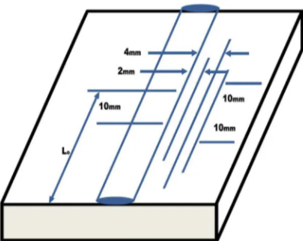
This new methodology consists of drilling five holes with 2 mm in diameter and 2 mm depth alongside the weld bead in the heat affected zone (HAZ) of the test plates (Fig. 1): two holes are spaced 2 mm from the edge of the weld bead and the another three 4 mm from the edge of the weld bead. All holes were machined with a drill bit.
Once drilled, the holes have been mapped on a coordinate measuring machine and then all test plates undergo a heat treatment for stress relief. After the displacements of the previously mapped holes were measured on the coordinate measuring machine.
2. Experimental Methods
In all experiments, plates of the naval steel ASTM A131 AH36 with 13.0mm thickness were used. Those were provided by the Atlântico Sul Shipyard. The test plates were cut in the dimensions of 180 mm x 60 mm x 13 mm, bevelled with an angle of 25º and a root height of 2 mm.
For welding, the following consumables were used: • Electrode wire ER70S-6 diameter 1.2 mm • Gas for welding (75% Air and 25% CO2) As welding equipment:
• Welding source with SmashWeld 318 TopFlex electrode wire feeder
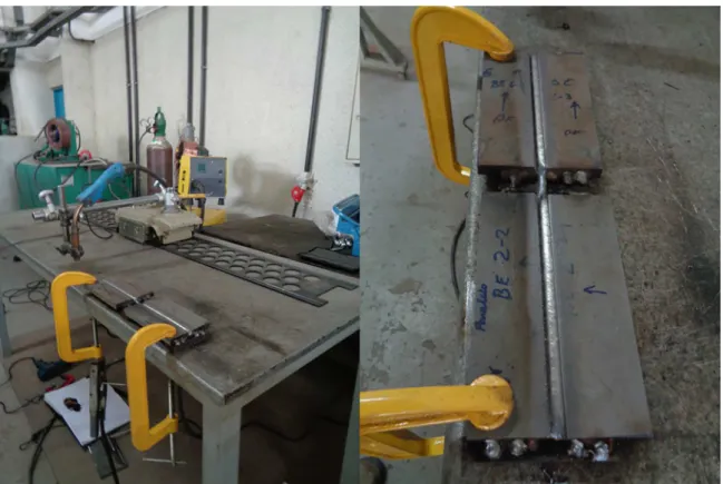
• System for automation - adapted cutting machine. Initially, metallographic analysis of the base metal was performed to identify the direction of lamination of the plate. Then the plates were welded by GMAW process, short circuit transfer mode, direct current with reverse polarity. The apparatus is mounted in such a way each pass could weld two pairs of test plates at once, one with the weld bead parallel to the rolling direction and the other with the weld bead in the cross direction of the rolling(Fig.2).
For each pass, a feedback was designed with the objective of maintaining the height torch nozzle / melt puddle constant, allowing a constant thermal input to each pass. In addition, each pass the welding direction was alternated, since, according to previous studies by the research group7,8,9, the alternation or maintenance of the welding direction influence the results of the residual stresses significantly.
Figure 1 . Schematic diagram of test plates.
Small variations in the welding parameters were produced to modify the heat input. According to Table 1, the welding speed decreased from 6.0 mm / s to 4.3 mm / s, resulting in a variation in the heat input from 390 KJ / min to 543 KJ / min.
After welding the test plates, holes of 2.0 x 2.0 mm were drilled and then mapped on a coordinate measuring machine with calibrated computer numerical control (calibration certificate 03206/2013). After mapping, all test plates were subjected to the heat treatment for the relief of stresses.
The heat treatment for the relief of residual stresses was carried out in a muffle furnace at a temperature of 650ºC for one hour. After this period the plates were air-cooled to room temperature. After cooling, the displacements of the holes were once again measured on the coordinate measuring machine. Then, calculations were made to determine the deformations and consequently the residual stresses in the five points of each test plate.
Based on the displacements of the mapped points, the deformations (Ɛ) were calculated by the equations 1 and 2 given below 1,7,8
(1)
(2)
Where: Ɛx deformation in x-direction; Ɛy deformation in x-direction;
xi initial coordinate in the x-direction before the heat treatment;
xf final coordinate in the x-direction after the heat treatment; yi initial coordinate in the y-direction before the heat treatment; yf final coordinate in the y-direction after the heat treatment. Based on values of the deformations, the residual stress values were calculated using equations 3 and 4:
(3)
(4)
Where:σx Residual stress in transverse direction of the the weld bead;
σy Residual stress in the longitudinal direction of the weld bead;
E Modulus of elasticity (GPa); ט Poisson coefficient.
3. Results and Discussion
The steel in its as-received condition had its microstructure analyzed to determine the direction of lamination of the sheet. The longitudinal section (Figure 3-a) showed that the direction of the lamination is very marked, revealing elongated grains in this direction and a texture remaining in the material. The cross-section (Figure 3-b), as expected, revealed equiaxed grains with no texture.
x
x x
x i f i f =
-y
y y
y i f i f =
-v
E v
1
x 2 x y
v = f f
-
Q
+V
v
E v
1
y 2 y x
v = f f
Figure 2. Apparatus mounted for welding
Table 1. Welding parameters
Plate Direction Number of
passes
Average voltage [V]
Average current [A]
Welding speed [mm / s]
Average heat input [kJ / m]
1 Transversal 08 18,5 170,0 6,0 390
2 Longitudinal 08 18,5 170,0 6,0 390
3 Transversal 06 18,5 163,3 4,3 543
4 Longitudinal 06 18,5 163,3 4,3 543
After the heat treatment, all of the test plates had their holes again mapped on the coordinate measuring machine. Based on the position differences, before (xi, yi) and after treatment (xf, yf), the displacements were measured and then the deformations were calculated by equations 1 and 2, and the residual stresses calculated by equations 3 and 4. The results of the calculations are presented in Table 2.
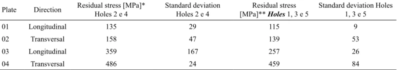
The results presented in Table 2 show that the holes located 2 mm from the edge of the weld bead have values of residual stresses greater than the holes 4 mm from the edge of the weld bead. This is justified by the greater plasticization produced in the points closest to the weld bead. According to measurements conducted with x-ray diffraction, Mendes et al8 found similar results. Using the same method, Melo et al9 also found similar results, considering points at the same distance from the weld bead and the thermal input of the same order of magnitude of this work.
The effect of anisotropy was also revealed in this study. The residual stresses were higher on the test sheets welded in the direction transverse to the rolling direction. This is justified by the existence of back stress in the rolling direction10. During the stress relief treatment, the plastification is attenuated by this back stress, reducing the displacements along the weld bead.
The comparison of welded plates 01 and 02 with 03 and 04 welded with a lower welding speed (28,3% less), results in an increase of the heat input, the residual stresses increased as well as, shown in Table 3.
4. Conclusion
The DCP method has proven to be an effective tool for measuring residual stresses in sheets or panels. This novel methodology makes it possible to take into account the directional effect (texture) of the sheet lamination during welding.
For the welded plates with lower heat input (plates 01 and 02), the values of the residual stresses (plates 01 and 02) at 2.0 mm from the weld bead were 158 MPa, for transversal direction and 135 MPa for longitudinal direction. For the points arranged at 4.0 mm from the weld bead, the residual stress values were 139 and 115 MPa for the transverse and longitudinal directions, respectively.
For the welded plates with the highest heat input (sheets 3 and 4) the residual stresses were 486 MPa for the transverse direction and 359 MPa for the longitudinal direction; hole at 2.0 mm from the weld bead. For the points at 4.0 mm from the weld bead the residual stresses were 459 MPa for the transverse direction and 257 MPa for the longitudinal direction.
5. References
1. Okumura T, Taniguchi C. Engenharia de Soldagem e Aplicações. Rio de Janeiro: LTC; 1982.
2. Withers PJ, Bhadeshia HKDH. Residual stress. Part 1 - Measurement techniques. Materials Science and Technology. 2001;17(4):355-365.
3. Wan Y, Jiang W, Li J, Sun G, Kim DK, Woo W, et al. Weld residual stresses in a thick plate considering back chipping:
Neutron diffraction, contour method and finite element
simulation study. Materials Science and Engineering: A. 2017;699:62-70.
4. Magalhães RR, Vieira AB Jr., Barra SR. The use of conventional strain gauges evaluation for measurements of residual stresses in welded joints. Journal of the Brazilian Society of Mechanical Sciences and Engineering. 2013;36(1):173-180.
5. Guimarães PB, Pedrosa PMA, Yadava YP, Barbosa JMA, Siqueira AV Filho, Ferreira RAS. Determination of Residual Stresses Numerically Obtained in ASTM AH36 Steel Welded by TIG Process. Materials Sciences and Applications. 2013;4(4):268-274.
Table 2. Values of residual stresses
Plate Direction Residual stress [MPa]* Holes 2 e 4
Standard deviation Holes 2 e 4
Residual stress [MPa]** Holes 1, 3 e 5
Standard deviation Holes 1, 3 e 5
01 Longitudinal 135 29 115 9
02 Transversal 158 47 139 53
03 Longitudinal 359 167 257 26
04 Transversal 486 24 459 84
*Holes located 2 mm from the edge of the weld bead
**Holes located 4 mm from the edge of the weld bead
Table 3. Increases of residual stress
holes longitudinal transversal
2 and 4 164 % 123%
1, 3 and 5 207% 230%
6. Noyan IC, Cohen JB. Residual stress: measurement by diffraction and interpretation. New York: Springer-Verlag; 2013.
7. Siqueira AV Filho, Rolim TL, Yadava YP, Cardoso FIB, Guimarães PB, Maciel TM, et al. Development of methodology for measurements of residual stresses in welded joint based on displacement of points in a coordinated table. Materials Research. 2013;16(2):322-326.
8. Mendes CE, Pina EAC, Gonçalves IL, Melo LGTC, Yadava YP, Rolim TL, Ferreira RAS. Influence of Temperature on Stress Relief Treatment in Steel Ah 36. In: 23nd International Congress of Mechanical Engineering (COBEM 2015), Rio de Janeiro, 2015.
9. de Melo LGTC, Cardoso FB, Mendes CE, Ferreira RAS, Barros
PS, Rolim TL. Welded Joints' Heat Affected Zone's Extension
Prediction by Switching Welding Parameters. Materials Research. 2017;20(Suppl 2):651-656.
10. Acoff VL, Wilkerson S, Arenas M. The effect of rolling
direction on the weld structure and hardness of gamma-TiAl sheet material. Materials Science and Engineering: A. 2002;329-331:763-767.