* e-mail: [email protected]
1. Introduction
Interstitial free (IF) steel has been widely used in the automotive industry due to its reasonable combination of high strength and formability and exhibits excellent deep drawability with a high plastic strain ratio, good elongation, high hardening index and low yield to tensile strength ratio. These advantages greatly enhance its application in sheet stampings for automobile manufacturing.1,2 The inclusion of accessories to meet the growing demands for safety and comfort in modern vehicles leads to an increase in weight and therefore fuel consumption. Thus the body in white must be lighter to compensate for the weight of these components. Therefore tailored blanks are used, which reinforce the body in white only in areas where a higher strength or stiffness is necessary. Nowadays the term “tailored blanks” refers to blanks that are manufactured from sheets with similar or different thicknesses by a welding process, adhesively bonded, or by a rolling process, making four subgroups: tailor-welded blanks, patchwork blanks, tailor-rolled blanks and tailor heat-treated blanks.3
The generation of residual stresses during manufacturing processes also causes unwanted and problematic deformation, which can be costly to correct. The large amount of non-uniform heat input inherent in most welding processes generates characteristic distributions of residual stress, which tend to have particularly adverse mechanical effects. This makes
welding a frequent cause of tensile residual stress problems in engineering practice.4,5 On the other hand, compressive stresses are sometimes introduced deliberately, such as by shot peening mechanical treatment, used to improve some beneits.6,7
The welding process is closely linked to the development of residual stresses. Thus, knowledge about the nature and magnitude of residual stresses at the end of the welding process is very important because it can directly inluence the component service life. However, automated welding processes such as LBW and PAW, in the context of residual stresses have not yet been studied in IF steel. Laser beam welding has been applied in the automobile industry because this process responds positively for the most demanding speciications with increase productivity and quality. The PAW process, whose development was based on gas tungsten arc welding (GTAW), is an innovative arc welding process, still little explored, but with great potential for applications in the automotive industry.8-9
The purpose of this work is to investigate the residual stresses resulting from Laser Beam Welding (LBW) and Plasma Arc Welding (PAW) processes by X-ray diffraction technique in IF steel butt joints. In addition, residual stresses in both welded joints with shot peening mechanical treatment were analysed by removal layer process. Microstructural analysis and mechanical properties characterization complemented this study.
Evaluation of Residual Stresses and Mechanical Properties
of IF Steel Welded Joints by Laser and Plasma Processes
Joanes Silva Diasa,b, Tatiane Campos Chuvasa,b, Maria da P. Cindra Fonsecaa*
a Department of Mechanical Engineering, Programa Francisco Eduardo Mourão Saboya de
Pós‑Graduação em Engenharia Mecânica – PGMEC, Universidade Federal Fluminense – UFF, Niterói, RJ, Brazil
b Department of Mechanical Engineering, CEFET‑RJ, Rio de Janeiro, RJ, Brazil
Received: September 16, 2015; Revised: January 12, 2016; Accepted: April 4, 2016
Interstitial free (IF) steel has an extensive application in the automotive industry where the Laser Beam Welding (LBW) process is widely used due to its high productivity. Similarly, the other used process, Plasma Arc Welding (PAW), is characterized by a greater energy concentration and current density and therefore lower distortion, higher welding speeds and higher penetration may be obtained. However, while the traditional welding processes have been extensively studied with regard to the generation of residual stresses, there are few studies about residual stresses analysis and characterization of LBW and PAW joints. Therefore, the aim of the present work is to analyse the residual stresses resulting from LBW and PAW processes by X-ray diffraction technique with sin2ψ method in IF steel butt joints. For both joints, macro and microstructure were characterized and mechanical properties were determined. Tensile residual stresses in the heat-affected zone (HAZ) and in the fusion zone (FZ) were veriied for both welding processes.
2. Material and Method
The present investigation has been conducted with 2 mm-thick titanium stabilized interstitial free (Ti-IF) steel. The chemical composition in weight per cent and the mechanical properties of the steel, obtained experimentally, are shown in Table 1 and 2, respectively.
The sheets are sectioned for test samples with a speciication of 200 mm x 150 mm using a CO2 laser equipment. The welding was made on a 200 mm edge in a butt joint square groove. The sheet surface was cleaned with a cotton ball dipped in acetone before welding to remove oil stains on the surface.
Laser welding was carried out using a high-power CO2 laser system. The sheets were arranged with the 1 mm gap between the parts surfaces, and rigidly held using pneumatically controlled clamps. Helium (He) was used as shielding gas through a coaxial nozzle to protect the fusion zone, with a 100 L/min gas low and 4 mm/s welding speed.
An EWM Tetrix 400 Plasma machine with an integrated Motoman SSF2000 robot and PCT 300 welding parameter software were used, allowing the whole plasma welding procedure to be supervised. The welding current and voltage were set at 110 A and 14.4 V, respectively. The welding torch stayed at the origin for a few seconds to ensure complete joint penetration and then it moved forward along the welding direction at a speed of 4.7 mm/s. Other process parameters can be summarized as follows: plasma gas (pure argon) low rate 2 L/min, shielding gas (pure argon) low rate 13.5 L/min. Figure 1 shows the appearance of samples in the top welding joint for both welding processes.
Surface residual stresses were measured by the X-ray diffraction (XRD) technique, based on Bragg’s law, using CrKα radiation (λCrkα = 2.29092 Å) diffracting the (211) plane for ferrite phase at 2θ = 156.41°. The stress measurement was performed in an XStress3000 portable analyser with a 1 mm collimator (30 kV, 6.7 mA), using the sin2ψ method for which the lattice spacing d of material was measured at ive ψ-angles between -45º and +45º. Based on a linear regression it, the variations of 2θ versus sin2ψ plots were recorded and the residual stress was evaluated. An accuracy of approximately 15 MPa was achieved using X-ray diffraction. The removal layer method used to obtain the proile of residual stress variations through the thickness was the electrolytic polishing, which consists on the electrolytic removal of the metal on a high ionic solution by means of electrical potential and current. A sodium chloride saturated solution with glycerin was used as electrolyte, and the voltage and current parameters were 30 V and 20 A, respectively.
The depth of the removed layer was determined with a digital dial gauge.
Residual stresses were measured in joints after laser and plasma welding and afterwards shot peened on the transversal (T) and longitudinal (L) direction of the weld bead, in the top and root region. These measurements were made in the base metal (BM), heat-affected zone (HAZ) and fusion zone (FZ). The extension of HAZ in PAW and LBW joints is 2.2 mm and 0.7 mm at the centre line of the FZ, respectively (Figure 2).
The shot peening treatment was performed according to SAE J442 speciication10, at an Almen intensity of 0.15 A, with N strip type, using glass shot with a diameter of 0.1 mm.
For optical micrograph the samples were prepared using conventional metallographic technique, with a inal polishing step in 1 µm diamond paste followed by a light etch at room temperature in 2% Nital solution, used to reveal ferrite grain boundaries. Second etching solution was composed of distilled water (50 ml), sodium thiosulfate (50 g) and potassium metabisulite (1 g) and samples were immersed in the solution for about 60 to 90 s.
Samples for the characterization of the mechanical properties were made according to ASTM A370-14 standard11
Table 1. Chemical composition of the investigated IF steel (% weight).
C Mn P S Si Al Ti Ni Cu Cr N
0.002 0.080 0.011 0.006 0.040 0.050 0.060 0.010 0.010 0.020 0.002
Table 2. Mechanical properties of the investigated IF steel (room temperature).
σYS (MPa) σUTS (MPa) ε (%) HV0.5
215 317 55 85
for the achievement of tensile tests, with gauge length and width set at 50 and 12.5 mm, respectively. Tensile tests were carried out with a 10 kN capacity Instron servohydraulic testing machine (model: 5966) with a cross-head velocity of 2 mm/min at room temperature. The Vickers microhardness test was carried out according to ASTM E384-11 standard.12
3. Results and Discussion
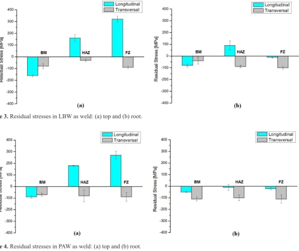
The surface residual stresses were analysed in longitudinal (L) and transversal (T) directions in the BM, HAZ and FZ, as shown in Figure 2 and the results are presented in Table 3 and in Figures 3 and 4. Uncertainty in the measurements is indicated by the error bars.
Analysing the values of residual stresses in Table 3 and Figures 3 and 4, in as-welded condition in both processes, on the top and at the root of the joints, it is possible to verify that the residual stresses at the top and the root were compressive in all analysed locations and directions, except in FZ and HAZ of the top surface and HAZ of the root surface in the longitudinal direction. In the FZ tensile residual stress is maximum and near the ultimate tensile strength of the base metal due to the very high heat input on the top side and inhomogeneous cooling process. Despite the high residual tensile stresses are located only in the longitudinal direction, it may affect the service life of the welded joint and can lead to premature failure of the Figure 2. Positions and directions of residual stress measurements
(in mm).
Figure 3. Residual stresses in LBW as weld: (a) top and (b) root.
Table 3. Residual stress on LBW and PAW welded joints.
Region
LBW PAW
Top [MPa]
Root [MPa]
Top [MPa]
Root [MPa]
L T L T L T L T
FZ 320 -90 -10 -100 270 -90 -20 -110
HAZ 160 -30 90 -90 180 -80 -10 -100
BM -160 -80 -80 -40 -90 -70 -50 -110
structure. However, this result is coherent with the one found by Coelho et al. (2013)7 and Acevedo & Nussbaumer (2012)13.
The residual stresses after both welding processes presented consistent results in the top region, where the surface tensile stresses are present in the centre of the weld seam, with lower surface tensile stresses on the HAZ, while the base metal has surface compressive stresses in the order of -100 MPa in the longitudinal direction, as shown in Figures 3a and 4a. The residual stress level is directly linked to restriction of the welding joints and with LBW and PAW being highly restricted processes, the different cooling contraction of the heated regions becomes the main source of residual stresses in the longitudinal direction, maximum restriction direction welded joints, resulting in tensile stresses on the FZ and HAZ. Nevertheless, in the transversal direction, all regions showed compressive residual stresses. In this case, both welding processes were performed using relatively high speeds and intensive cooling of the surfaces associated with microstructural changes that occur in the FZ and HAZ resulting in a compressive residual stress surface, on the top and at the root.
The results of residual stresses generated in welding by both processes (LBW and PAW) also show that there is no difference in the residual stresses ields in these joints and, therefore, there is no superiority of one process compared to another, in this context.
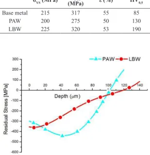
After the shot peening treatment, residual stresses were changed to homogeneous compressive values of about -300 MPa for both welding processes. In Figure 5 the residual stresses subsurface proiles in FZ are shown. If comparing the residual stress levels in both samples, the PAW welded sample presents a more compressive ield than the LBW sample, in spite of the similar value in the surface and the same shot peening treatment. The largest gradient between them occurs at a depth of 50 µm where the compressive residual stresses in the plasma weld reaches its peak, about -450 MPa.
The subsurface behaviour of these stress ields in the proiles obtained through the thickness for both processes analysed up to a depth of 140 µm can be seen in Figure 5.
Tensile stresses remained compressive up to depths of 120 µm and 100 µm for LBW and PAW, respectively, and thus inverted the nature of the stresses.
In the Figure 6 the base metal optical microstructure that consists in equiaxed ferrite grains is presented.
Figure 7 shows the welded joint cross-section microscopy of LBW and PAW processes. It was observed that the weld was performed without porosity and cracks. Both welding processes showed in the fusion zone microstructure (Figure 8) formed by the equiaxed ferrite grains with irregular shapes and sizes. Signiicant grain growth was observed in the HAZ region and this result is coherent with that found by Bayraktar et al. (2007).14
Table 4 lists the obtained mechanical properties of base metal and welded joints.
The tensile tests showed that the fracture occurred on the base metal in both, LBW and PAW, processes, although the specimens have been manufactured transversely the weld joint (Figure 9). This clearly shows that the fusion zone is not the portion where the crack would start when it is deformed in tensile test. The ultimate tensile strength
(UTS) values obtained in both processes were very close to the base metal as shown in Table 4.
An SEM micrograph analysis of the samples fractured surface of IF steel was carried out. The observed dimples were characteristic of the micromechanism of a ductile fracture, i.e. void nucleation, growth and coalescence. The precipitates that caused the void nucleation were still visible on the bottom of the dimples. Figures 10 and 11 show the SEM micrographs of the fracture surfaces. The fracture surface near the specimen surface showed a combination of both equiaxed and elongated dimples near the edge, indicating the occurrence of shearing motion 15.
The Vickers microhardness proiles performed on the weld joint cross section in LBW and PAW are shown in Figure 12. It was observed that the microhardness in the metal
Table 4. Mechanical properties.
σYS (MPa) σUTS
(MPa) ε (%) HV0,5
Base metal 215 317 55 85
PAW 200 275 50 130
LBW 225 320 53 190
Figure 5. Residual stress proile through the thickness of both
welded joints.
base was 85 HV; in the fusion zone in PAW it was already close to 130 HV, while in the LBW there was an increase of about 40% in this zone (190 HV), coherent with that found by Coelho et al. (2013).7 In both welding processes, different widths
Figure 7. Heat affect zone (a) LBW and (b) PAW. 500X.
Figure 8. Fusion Zone (a) LBW and (b) PAW. 500X.
with high heat input, which doesn’t happen in LBW, and it is known that PAW offers greater energy density and thermal eficiency than conventional arc welding processes.
4. Conclusions
In this study, surface and subsurface residual stresses resulting from Laser Beam Welding (LBW) and Plasma Arc Welding (PAW) processes by X-ray diffraction technique in IF steel butt joints were analysed. In addition, microstructural analysis and mechanical properties were examined. The following conclusions can be drawn from this work:
1. The residual stresses on the top and at the root of the joints have very similar magnitudes between the welding processes. High longitudinal tensile residual stresses were veriied in HAZ (~170 MPa) and FZ (~300 MPa) for both welding processes on the top side.
2. The compressive and homogeneous residual stresses (-300 MPa) introduced by shot peening treatment for both welding processes, analysed through the thickness of the material, showed that residual compressive behaviour remained up to a depth of approximately 110 µm before becoming tensile. The largest gradient between them occurs at a depth of 50 µm where the residual stresses in the plasma weld reaches its compressive peak of about 450 MPa.
3. It was observed that failure process of the specimens from both welding processes occurred in the base metal, characterizing high structural integrity of the both welded joints. The ultimate tensile strength (UTS) values obtained in both cases were very close to the base metal. SEM micrographs of the samples fractured surface were observed and conirmed the micromechanism of a ductile fracture.
4. The Vickers microhardness in the fusion zone in LBW was about 40% more than in PAW due to the high energy densities.
Acknowledgements
The authors are grateful to the Brazilian research agencies CNPq, CAPES and FAPERJ for their support in this work.
Figure 12. Microhardness proiles of the samples.
Figure 10. SEM: Fractured surfaces of LBW with ductile dimples. 500X.
Figure 11. SEM: Fractured surfaces of PAW with ductile dimples. 500X.
References
1. Zhao H, Rama SC, Barder GC, Wangb Z, Wangb X. Experimental study of deep drawability of hot rolled IF steel. Journal of Materials Processing Technology. 2002;128:73–79. http:// dx.doi.org/10.1016/S0924-0136(02)00230-3
2. Zhang Y, Zhang Y, Yang F, Zhang Z. Effect of alloying elements (Sb, B) on recrystallization and oxidation of Mn-containing IF steel. Journal of Iron and Steel Research
International. 2013;20(3):39–44. http://dx.doi.org/10.1016/ S1006-706X(13)60067-9
3. Merklein M, Johannes M, Lechner M, Kuppert A. A review on tailored blanks-production, applications and evaluation. Journal of Materials Processing Technology. 2014;214(2):151–164. http://dx.doi.org/10.1016/j.jmatprotec.2013.08.015
5. Chuvas TC, Garcia PSP, Pardal JM, Fonseca MPC. Influence of heat treatment in residual stresses generated in P91 steel-pipe weld. Materials Research. 2015;18(3):614-621. http://dx.doi. org/10.1590/1516-1439.006315
6. Withers PJ, Bhadeshia HKDH. Residual stress. Part 1 - Measurement techniques. Materials Science and Technology. 2001;17(4):355-365. http://dx.doi.org/10.1179/026708301101509980
7. Coelho RS, Corpas M, Moreto JA, Jahn A, Standfuß J, Kaysser-Pyzallaa A, Pinto H. Induction-assisted laser beam welding of a thermomechanically rolled HSLA S500MC steel: A microstructure and residual stress assessment. Materials Science & Engineering A. 2013;578(20):125-133. http://dx.doi. org/10.1016/j.msea.2013.04.039
8. Li XR, Heusman J, Kvidahl L, Hoyt P, Zhang YM. Manual keyhole plasma arc welding with application. Welding Research.
2011;90:258-264.
9. Sánchez-Tovar R, Montañés MT, García-Antón J. Effect of different micro-plasma arc welding (MPAW) processes on the corrosion of AISI 316L SS tubes in LiBr and H3PO4 solutions under flowing conditions. Corrosion Science. 2010;52:1508-1519. http://dx.doi.org/10.1016/j.corsci.2009.12.023
10. Society of Automotive Engineers - SAE. SAE J442. Test strip, holder and gage for shot peening. SAE International; 1995.
11. American Society for Testing and Materials - ASTM. ASTM A370‑14. Standard Test Method for mechanical testing of steel products. West Conshohocken, PA: ASTM; 2014.
12. American Society for Testing and Materials - ASTM. ASTM E384‑11. Standard test method for Knoop and Vickers hardness of materials. West Conshohocken, PA: ASTM; 2011.
13. Acevedo C, Nussbaumer A. Effect of tensile residual stresses on fatigue crack growth and S–N curves in tubular joints loaded in compression. International Journal of Fatigue. 2012;36(1):171-180. http://dx.doi.org/10.1016/j.ijfatigue.2011.07.013
14. Bayraktar E, Kaplan D, Devillers L, Chevalier JP. Grain growth mechanism during the welding of interstitial free (IF) steels.
Journal of Materials Processing Technology. 2007;189(1-3):114-125. http://dx.doi.org/10.1016/j.jmatprotec.2007.01.012