Abstract
The present work describes part of the R&D on using a semi-active structural control technique in a civil engineering experimental model frame equipped with a MR damper, developed within COVICOCEPAD project approved in the framework of Eurocores program S3T. Some results are provided associated with the calibration of a MR damper at FEUP as well as on the experimental modal identification of the dynamic properties of a small-scale metallic frame, without and with inclusion of a specific MR device. Some numerical results of the controlled frame under simulated earthquakes are given, to be compared with the experimental results of such frame installed in a Quanser shaking table.
Keywords: semi-active control, control of vibrations for smart structures, magneto-rheological dampers, semi-active devices.
1 Introduction
Structural control has an extensive and successfully history in mechanical, aerospace and related engineering fields. The vast quantity of successful applications in these knowledge areas lead to the opening of new research paths namely in civil engineering structures. However the application of structural control techniques to the response of large civil engineering structures is more challenging due to the amount of energy involved in the control process arising from environmental actions such as strong wind or seismic excitation.
In the last two decades R&D of structural vibration control devices for buildings and bridges has been intensified to reply to construction market needs that demand more effective systems to decrease the damage caused by seismic and wind loading. This orientation is the result of a public necessity to guarantee the serviceability of construction lifelines throughout and after the occurrence of a moderate or severe seismic event (Barros et al. [1] [2]).
Paper
169
Semi-Active Vibration Control of a
Three Degree-of-Freedom Scaled Frame with a
Magneto-Rheological Damper
M.B. Cesar1 and R.C. Barros2
1
Department of Applied Mechanics
Polytechnic Institute of Bragança (IPB-ESTiG), Portugal
2
Department of Civil Engineering, Faculty of Engineering University of Porto (FEUP), Portugal
©Civil-Comp Press, 2010
Although the main purpose of a seismic design is to protect the population from the consequences of a severe earthquake, the protection of investment may also be regarded as an important option during the conception and design process.
Seismic isolation and passive energy dissipation devices are two well-established techniques validated by huge amount of real applications (Naeim and Kelly [3]; Cesar and Barros, [4]). The potential of structural control to reduce the response of large buildings to strong wind excitation has been largely realized using passive tuned mass dampers (TMD’s) or active mass dampers (AMD’s).
However, passive systems are tuned to have specific dynamic property and therefore some uncertainties about the response under large earthquakes remains. To avoid this matter, active control systems for structural vibration mitigation for wind and traffic excitations were developed and have been successfully implemented in real applications. Basically the idea is that the control systems for civil engineering applications must be able to respond fast enough to a control signal in order to generate high dissipative forces with low power supply.
In this context, magneto-rheological (MR) fluid based devices have the appropriate features to satisfy all these requirements justifying the relevance of these for possible civil engineering applications and therefore the attention of researchers to study its potential as vibration control hardware. In addition, the control strategy for these devices is based on semi-active control that may be more reliable and stable than active control.
In this paper is addressed some on-going R&D on the vibration control of a 3-DOF scaled metallic frame with a MR damper (Barros et al. [5], Cesar and Barros [6]). An equivalent device was tested in the laboratory to obtain the rheological characteristics in order to develop a numerical model simulating its behaviour. A 3-DOF scaled frame was assembled and system identification techniques using an impact hammer procedure were performed to obtain the experimental dynamic properties of this structural system. The MR damper was then assembled in the scaled frame and a new identification procedure was carried out to verify the influence of this device (without and with internal coil electrical current) in the frame dynamic behaviour. Based on these results a numerical model was created to initiate the semi-active control research in order to investigate and calibrate the frame behaviour with the MR damper.
2 Semi-Active Control of Structures with MR Dampers
2.1 Introduction
The strategies based upon passive control – namely the base isolation (BI) systems, shock absorbers (SA) and tuned mass dampers (TMD) – are well known and accepted methodologies due to its effectiveness as a mitigation approach for dynamic loading.
However, the limitations that these devices/methodologies have to allow variations of the dynamic loading or structural parameters encouraged the study and development of more advanced control systems based on active, semi-active or hybrid control devices (Figure 1).
M
K C
ξ xp
M
K C
ξ xp
M
K C
ξ xp
Fc
Figure 1. Active and semi-active vibration control strategies
The numerical models used to simulate this new type of control in civil engineering structures allow to conclude that it is possible to apply them successfully but some experimental research is required to validate these models in order to be accepted as a possible structural vibration control solution. Also, the practical application of active control to some civil engineering structures can easily become analytically cumbersome for immediate implementation, as was emphasized by Barros [7] for the case of pipeline shell structures with ring stiffeners (but also of interest to fuselage structures as well).
Since active devices are not a practical and reliable option in the near future as a structural building or bridge control systems due to energy demand and possible failure in case of power loss, semi-active control devices gained significant attention by the civil engineering community in the last years because they have at the same time the benefits of passive and active de-vices without requiring a huge amount of energy to work properly.
2.2
Magneto-rheological dampers
The next stage is to use semi-active devices to control the vibration of a base excited structure. Among the possible semi-active technologies, the magneto-rheological fluid (MRF) based devices are seen as a promising solution for structural control (Barros et al. [5], Barros [8], Cesar and Barros [6]).
Basically two types of rheological fluids can be used to create a structural control system: magneto-rheological (MR) and electro-rheological (ER) fluids. MR fluids are materials that exhibit a change in rheological properties with the application of a magnetic field while ER fluids exhibit rheological changes when an electric field is applied to the fluid.
For vibration control purposes the “smart” MR fluid effect is interesting since it is possible to apply this phenomenon to create a variable damping device or a “smart” hydraulic damper. The current applied to a MR fluid essentially allows controlling the damping force without the need of mechanical valves that are commonly used in adjustable dampers. This offers the possibility to create a reliable damper since a failure in the control system reverts the MR damper to a passive damper (Figure 2).
Figure 2. Schematic representation of a magneto-rheological damper
The MR damper performance is often characterized by using the force vs. velocity relationship. Regular viscous damper has an ideal linear constitutive behaviour and the slope of the line is known as the damper coefficient. In the case of MR dampers the possibility to change the damping characteristics leads to a force vs. velocity envelope that can be described as an area rather than a line in the force-velocity plane. This behaviour is the fundamental condition to build a “smart” damper since it is possible to design a controller to follow any force-velocity relationship within the envelope to create a control strategy.
According to the available bibliography two common methods can be used to model MR devices such as MR dampers: the parametric modelling technique that characterizes the device as a collection of springs, dampers, and other physical elements; the non-parametric modelling that employ analytical expressions to describe the characteristics of the modelled devices.
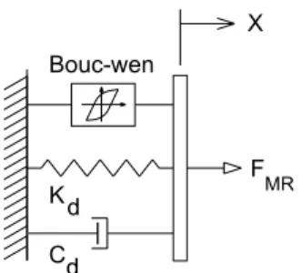
Many authors have developed modelling techniques for the MR dampers based on both methods. The Bouc-Wen model in Figure 3 allows modelling nonlinear hysteretic systems and is frequently used to model MR dampers (Dyke et al. [9]).
K C d d Bouc-wen
X
F MR
Figure 3. Bouc-Wen model for a MR damper In this model the MR force can be computed by
(
)
0 0 0
MR
In this equation FMR is the predicted damping force, k0 is the accumulator
stiffness, c0 is the viscous damping and z is the evolutionary variable of the first
order nonlinear differential equation
1
n n
z= −γ x z z − −βx z +Ax (2)
The parameters β, γ and A allows controlling the linearity in the unloading and the smoothness of the transition from the pre-yield to the post-yield region.
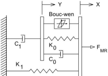
Dyke et al. [9] also presented a modified parametric model based on the extension of the previous Bouc-Wen model, which allows a good approximation to the real MR damper behaviour as shown in Figure 4.
C K C 1 1 0 0 Bouc-wen Y X F MR K
Figure 4. Modified Bouc-Wen model for a MR damper
The modified Bouc-Wen model is based on the Markov-vector formulation to model nonlinear hysteretic systems and according with the modified model shown in Figure 4, the MR force can be computed by
FMR =c y1+k x1
(
−x0)
(3)(
)
{
(
)
}
(
)
(
)
0 0 0 1 1 1 n ny z c x k x y
c c
z x y z z x y z A x y
α
γ − β
⎧ = + + − ⎪ + ⎨ ⎪ = − − − − + − ⎩ (4)
In these equations z is the revolutionary variable, FMR is the predicted damping
force, k1 is the accumulator stiffness, c0 is the viscous damping observed at larger
velocities and the parameters β, γ and A allow controlling the linearity in the unloading and the smoothness of the transition from the pre-yield to the post-yield region. The dashpot c1 is included to produce the roll-off at low velocities, k0 is used
to control the stiffness at larger velocities, and x0 is the initial displacement of spring
k1 associated with the nominal damper due to the accumulator.
(
)
1 1 1
0 0 0
a b
a b
a b
c c c u
c c c u
u
u u v
The damping constants c0 and c1 depend on the electrical current applied to the
MR damper. The variable u is the current applied to the damper through a voltage-to-current converter with a time constant η and the variable v is the voltage applied to the converter.
2.3 Semi-active control algorithms
The equation of motion that describes the behaviour of a controlled building under an earthquake load, Barros et al. [5], is given by:
g
Mx Cx+ +Kx= −Γ −f M xλ (6)
where M is the mass matrix, C is the damping matrix, K is the stiffness matrix, x is the vector of floors displacements, x and x are the floor velocity and the acceleration vectors respectively, f is the measured control force, λ is a vector of ones and Γ is a vector that accounts for the position of the MR damper in the structure.
This equation can be rewritten in the state-space form as
g
z=Az+Bf +Ex (7)
y=Cz+Df +v (8)
where z is the state vector, y is the vector of measured outputs and v is the measurement noise vector. The other matrix quantities are defined by
1 1 1
1 1 1
0 0 0
0 0
I
A B E
M K M C M
M K M C M
C D
I
λ
− − −
− − −
⎡ ⎤ ⎡ ⎤ ⎡ ⎤
=⎢ ⎥ =⎢ ⎥ = −⎢ ⎥
− − Γ
⎣ ⎦ ⎣ ⎦ ⎣ ⎦
⎡− − ⎤ ⎡ Γ⎤
=⎢ ⎥ =⎢ ⎥
⎣ ⎦ ⎣ ⎦
(9)
To control this semi-active structure based on a control force determination, usually are measured: the absolute acceleration of some relevant selected points in the structure; the displacement of the control device; and the control force.
After computing the state space model it is necessary to select a proper control algorithm to efficiently use this device in reducing the dynamic response of structural systems. Obviously, the control strategy depends on the MR damper model selected to simulate the nonlinear hysteretic behaviour of this device (Jansen and Dyke [10], Kang-Min et al. [11]).
As mentioned before this work is based on the Bouc-Wen model that can represent the hysteresis dynamics explicitly. Therefore, an efficient control algorithm must be developed or chosen from the available research bibliography to correctly characterize the intrinsic MR fluid behaviour, maximizing the MR damper characteristics as a semi-active control device (Barros et al. [5]).
In the last few years several approaches have been proposed and intensively studied for better selection of the input voltage that must be applied to the MR damper to achieve the maximum performance. Among the proposed strategies the following are the most studied: Lyapunov Based Control; Decentralized Bang-Bang Control; LQG (Linear Quadratic Gaussian) or Clipped-Optimal Control; H2/LQG control; Fuzzy Control and also Artificial Neural Network (ANN) control strategies. Some of these control strategies will be applied later in the R&D program in order to understand the pros and cons of each strategy; however, in the cur-rent numerical study only a control based upon Lyapunov stability theory will be presented.
In the context of the dynamic behavior of bridges, equipped with adaptative protection systems, a very special velocity displacement and displacement dependent semi-active control algorithm has been developed and successfully applied (Oliveira and Guerreiro [12], Guerreiro et al. [13], Oliveira et al. [14], Oliveira [15], Guerreiro et al. [16]).
In this study a Lyapunov theory based control and a Clipped-Optimal control will be used. Lyapunov direct approach was used as a possible semi-active control of MR dampers during the development of control strategies for these devices (Dyke and Spencer [17]). This approach is classified as a bang-bang controller and is dependent on the sign of the measured force and on the states z of the system. According with this approach, it is necessary to define a Lyapunov function or V(z) that is a positive definite function of the state z of the system. If the rate of change of the Lyapunov function is negative semi-definite, the origin is stable in the sense of Lyapunov.
Therefore, control inputs for the MR damper must be selected in order to make V as negative as possible. In this case, and following previous research in this filed (Cesar and Barros [6]), the Lyapunov function was chosen of the form:
( )
2
2
p
z
V z = (10)
where ||z||p is the P-norm of the z-states defined by
[
]
0.5'
p
z = z P z (11)
and P is a real, symmetric, positive definite matrix. To ensure that the derivative of V is negative definite, the matrix P is found using the Lyapunov equation
1
' ' '
2 p g
V= z Q z+z P B f +z P E x (12)
Therefore, the control law that will minimized this function is
(
)
max '
where H is the Heaviside step function. To implement this algorithm, a Kalman filter was used to estimate the states based on the available measurements (MR damper displacements and structural accelerations).
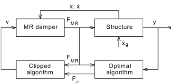
The Clipped Optimal control algorithm shown in Figure 5 has proved to be a good strategy to implement semi-active MR devices in civil engineering structures.
MR damper F
MR
Structure
Optimal algorithm Clipped
algorithm F
MR
F
d
y v
x, x.
x.g
Figure 5. Clipped Optimal controller for a MR damper
This strategy consists of a Bang-Bang (on-off) controller that causes the damper to generate a desirable control force which is determined by an “ideal” active controller (in state feedback form). A force feedback is used to produce the desired control force fd, which is determined by a linear optimal controller Kk(s), based on
the measured structural responses y and the measured damper force fc. The linear
controller is obtained with a LQG strategy (in this study). Only applied voltage va
can be commanded and not the damper force. The algorithm for selecting the voltage is
(
)
max
a d c c
v =v H f − f f (14)
in which vmax is the voltage level associated with the saturation of the magnetic field
in the MR damper and H is the Heaviside step operator.
The following voltage selection algorithm is applied: When the actual force being generated by the damper fc equals the desirable force fd, the voltage applied remains
the same; when the magnitude of the force fc is smaller than the magnitude of fd and
both forces have the same sign, then the voltage applied is set to its maximum level to increase the damper force; otherwise, voltage is set to zero.
3
Experimental Setup
3.1
The MR damper and the scaled metallic frame model
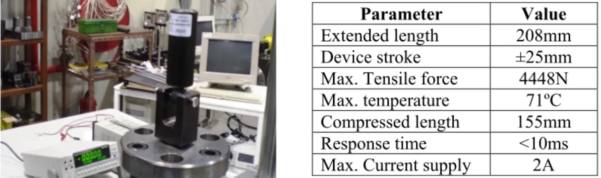
To study the behaviour of a MR damper some experiments were carried out on a MTS universal testing machine (Mechanical Engineering Laboratory at FEUP) with the MR damper device RD-1005-3 supplied by LORD Corporation (Figure 6).
Parameter Value
Extended length 208mm Device stroke ±25mm Max. Tensile force 4448N Max. temperature 71ºC Compressed length 155mm Response time <10ms Max. Current supply 2A Figure 6. Magneto-rheological damper RD-1005-03 test setup at FEUP
The MR damper was attached to the MTS machine (operating under displacement control mode) and a 5 kN load cell was incorporated at the upper head to measure the force applied to the damper. The results were automatically collected by the computer-controlled MTS equipment and stored in a desktop PC.
After assemblage, the MR damper was forced with a sinusoidal signal at a fixed frequency, amplitude and current supply. To obtain the response of the MR damper under several combinations of frequencies, amplitudes and current supplies a series of tests were carried out. A set of frequencies (0.5, 1.0, 1.5 and 2.0 Hz), amplitudes (2, 4, 6, 8 and 10 mm) and current supplies (0.0, 0.1, 0.2, 0.25, 0.5, 0.75, 1.0 and 1.5 A) were used to complete the test program (Barros et al. [5], Cesar and Barros [6]).
In order to control and avoid temperature failure, especially at higher frequencies, a thermo-couple was used to measure the external temperature of the MR damper. Typical results of this set-up of the experimental research are shown in Figures 7 and 8.
Figure 7. MR damper RD-1005-03 Force-Time History (1.5 A , 10mm)
Several authors developed methodologies to obtain the rheological behaviour of the RD-1005-03 MR damper. Based on the modified Bouc-Wen model, Basili [18] performed an experimental research in order to identify the parameters associated with this model, to find the following voltage (V) dependent parameters:
( )
20 1.25 4.15 1.62
c V = − V + V+ (15)
( )
21 11.53 37.68 11.87
c V = V + V + (16)
( )
258 112 51
V V V
α = + + (17)
The voltage independent parameters obtained were: k0=2.02 N/mm, k1(x-x0)=60 N, β=γ=0.5, A=1.0 (this values were previously fixed in order to obtain the voltage dependent values), uy= 0.05 mm and n= 2.0.
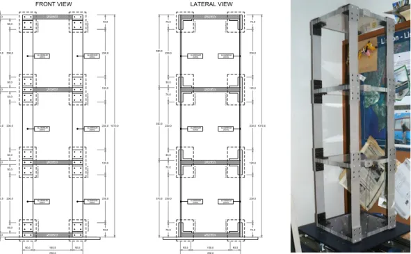
According with the scheduled research program the next stage was related with study the experimental dynamic behaviour of a 3DOF scaled metallic load frame with and semi-active devices. Among the several possible control strategies that can be easily used with this scaled frame, Tuned Mass Dampers (TMD), Tuned Liquid Dampers (TLD) and a Base Isolation system (BI) are the more simple to implement due to its passive behaviour. However, the structural setup was developed to allow semi-active control that was performed with a MR damper connected horizontally at the first floor level. A hybrid control system, based on the association of base isolation and MR dampers, can also be considered in the research program but it will not be addressed in this study. The experimental scaled building is a single bay three-storey frame in shear frame configuration (Figure 9) with the columns at the corner having the same stiffness.
C onnec tion 2 C onnec ti on 2 C onnec ti on 2 C onnec tion 1 C onnec tion 1 C onn ec tio n 1 C onn ec tio n 1 ALUMINIUM ALUMINIUM ALUMINIUM ALUMINIUM ALUMINIUM C onnec tion 2 C onnec tion 2 C onnec tion 1 C onnec ti on 2 C onnec ti on 2 C onnec tion 1 C onnec tion 1 ALUMINIUM ALUMINIUM ALUMINIUM ALUMINIUM ALUMINIUM C onnec tion 1 FRONT VIEW 230,0 50,0 50,0 50,0 230,0 50,0 50,0 230,0 50,0 330,0 20,0 330,0 20,0 330,0 20,0 290,0 190,0 50,0 50,0 290,0 190,0 50,0 50,0 PLEXIGLASS PLEXIGLASS PLEXIGLASS PLEXIGLASS
ALUMINIUM(50X5) (50X5)
(50X5) (50X5) (50X5) (50X5) 20,0 PLEXIGLASS PLEXIGLASS PLEXIGLASS PLEXIGLASS 230,0 50,0 70,0 230,0 50,0 70,0 230,0 70,0 370,0 350,0 350,0 70,0 230,0 120,0 230,0 120,0 230,0 70,0 1070,0 70,0 230,0 120,0 230,0 120,0 230,0 70,0 1070,0 70,0 (50X5) (50X5) ALUMINIUM (50X5) (50X5) (50X5) (50X5) C onnec tion 2 LATERAL VIEW
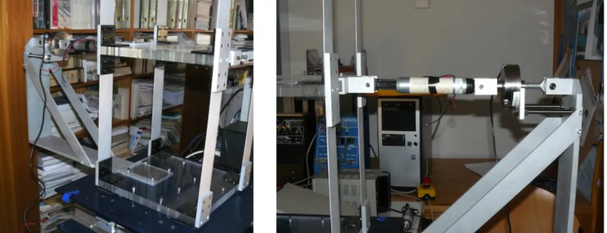
This experimental frame located at FEUP-Covicocepad Lab, can be forced dynamically using the Quanser shaking table II as the dynamic loading actuator.
The experimental research can employ three control strategies: (1) a passive control based on base isolation devices; (2) a semi-active control based on a MR damper assembled to the structure; (3) a hybrid control technique through the association of the base isolation devices with the MR damper (Barros et al. [5], Cesar and Barros [6]).
To study the semi-active control strategy a small MR damper was placed horizontally at the first floor level attached to the frame and rigidly attached to the shaking table as shown in Figure 10. To acquire the damping force generated during the experimental tests a load cell is placed in the MR damper support system.
Figure 10. MR damper attached to the experimental metallic frame
The small size and mass of the scaled frame does not allow the use of RD-1005 MR damper since the force range of this device is beyond the dynamic forces expected during the experimental research. Therefore, a small MR damper shown in Figure 11 was used (RD-1097 from Lord Corporation) gently provided by Prof. Vincenzo Gattulli from D.I.S.A.T, L’Aquilla University in Italy (Gattulli et al. [19]).
Figure 11. RD-1097 MR damper from Lord Corporation
The same procedure was used to obtain the rheological behaviour of the RD-1097-01 MR damper. This was the selected device to be used in this analysis due to the small range of forces involved in the scaled frame dynamic analysis. In order to use the Bouc-Wen model, the following current (I) dependent parameters were used:
( )
3 272.80 42.88 14.83 0.29
I I I I
α = − + + (18)
( )
4 3 29.37 10.22 4.33 0.89 0.02
d
c I = − I + I − I + I+ (19)
And the current independent parameters are: k0=0.0, β= -7.078, γ=10.614, A=36.21
and n= 1.0. These are approximate values (Shen et al. [20]), that proved to capture very well the hysteretic behaviour of the MR damper.
3.2
System identification of the metallic frame without MR damper
In this section the details of the parameter identification of the metallic frame alone (with-out the MR damper/metallic frame association) are presented.
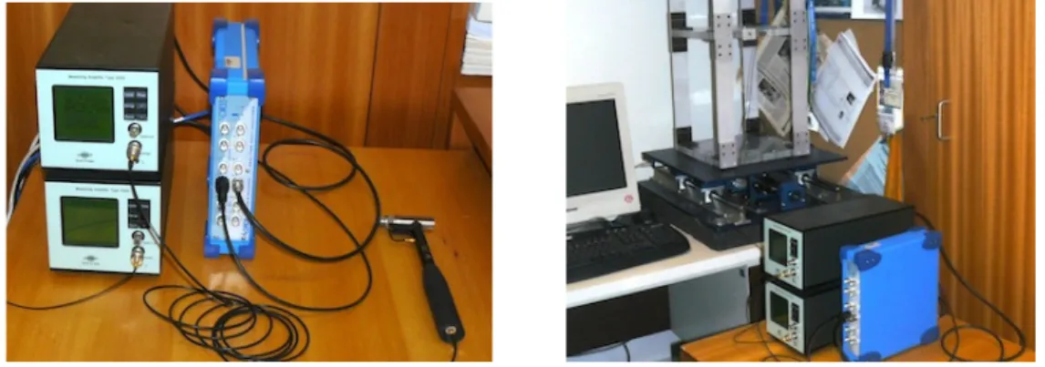
An impulse hammer test was carried out in order to obtain the dynamic behaviour of the structure in response to an applied excitation. The main purpose was to obtain the transfer function or Frequency Response Function (FRF) of the experimental frame (Figure 12). The structural response was measured with a piezoelectric accelerometer (Bruel & Kjaer type 4393 with measuring amplifier type 2525) placed at the first floor and a portable real-time Analyzer (OROS 35 real-time multi-analyzer) that was used to perform the necessary mathematical rationing on input and response signals to produce the desired transfer function. To perform the identification an impulsive force was given with the impact hammer at the centre of each floor plate and the acceleration response was measured at the first floor plate along the direction of the impulse.
Figure 12. Identification and acquisition hardware
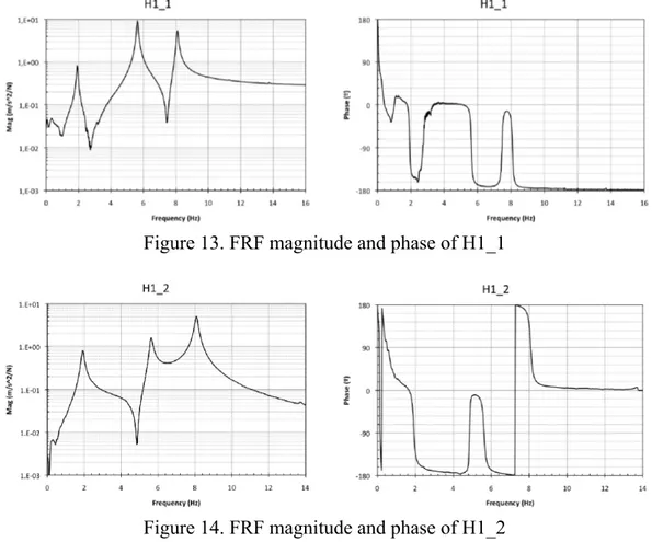
Figure 13. FRF magnitude and phase of H1_1
Figure 14. FRF magnitude and phase of H1_2
Figure 15. FRF magnitude and phase of H1_3
The parameters of the scaled frame were then obtained based on the data provided by these functions and are tabulated in Table 1.
Frequency Damping Modal Participation
Mode 1 1,913986 0,03157 34,43248 Mode 2 5,627778 0,01198 35,25975 Mode 3 8,086245 0,00899 30,30777
The Modal Assurance Criterion (MAC) was used to validate modal data. The function of the MAC is to provide a measure of consistency (degree of linearity) between estimates of a modal vector. This function is defined by the following expression (Ewins [21]):
(
)
(
)(
)
2
,
T
m a
j k j k m T m a T a
j j k k
MAC
φ φ
φ φ φ φ
⎡ ⎤ ⎡ ⎤ ⎣ ⎦ ⎣ ⎦ =
⎡ ⎤ ⎡ ⎤ ⎡ ⎤ ⎡ ⎤ ⎣ ⎦ ⎣ ⎦ ⎣ ⎦ ⎣ ⎦
(20)
This provides an additional confidence factor in the evaluation of a modal vector from different excitation locations or different modal parameter estimation algorithms. Applying this procedure the following MAC matrix was obtained
MAC=
1.000 0.501 0.031
0.501 1.000 0.228
0.031 0.228 1.000
⎡
⎣ ⎢ ⎢ ⎢
⎤
⎦ ⎥ ⎥ ⎥
(21)
The MAC takes on values from zero, representing no consistent correspondence, to one, representing a consistent correspondence. Therefore, if the modal vectors under consideration truly exhibit a consistent relationship, the modal assurance criterion should approach unity and the value of the modal scale factor can be considered to be reasonable.
3.3
System identification of the metallic frame with MR damper
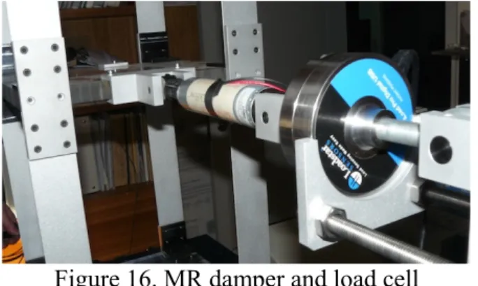
To study the influence of the MR damper in the dynamic behavior of the structural system, a new identification procedure was carried out after connecting the MR damper to the experimental frame as shown in Figure 16. A load cell was also attached to the system allow measuring the generated axial force in the MR damper.
Figure 16. MR damper and load cell
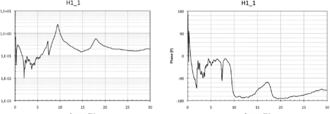
Figure 17. FRF magnitude and phase of H1_1 with MR damper at 0.0A
Figure 18. FRF magnitude and phase of H1_2 with MR damper at 0.0A
Figure 19. FRF magnitude and phase of H1_3 with MR damper at 0.0A
A simple study of the FRF functions allows concluding that the inclusion of the MR damper changes the natural frequencies and more obviously the amount of structural damping. The frequencies were slightly shifted to higher values since the MR damper adds stiffness to the system and the expected damping properties of a device as a damper significantly reduce the time response.
Figure 20. FRF magnitude and phase of H1_1 with MR damper at 0.5A
Figure 21. FRF magnitude and phase of H1_2 with MR damper at 0.5A
Figure 22. FRF magnitude and phase of H1_3 with MR damper at 0.5A
4
Numerical Results
To study the response of the model structure with the semi-active controller, a few characteristic earthquake records were considered and some MATLAB/SIMULINK routines were developed. The earthquake records will be also input in the Quanser shaking table of FEUP-Covicocepad laboratorial facilities, in order to experimentally calibrate and numerically compare different control strategies. Herein El Centro earthquake record was selected as input for the Lyapunov based controller, and El Centro and Kobe-NIS earthquake records for the Clipped-Optimal control Algorithm (Figure 23-24).
Figure 23. El Centro earthquake signals for semi-active control (Lyapunov and Clipped-Optimal)
Figure 24. Kobe NIS earthquake signals for semi-active control (Clipped-Optimal)
The acceleration at the 3rd floor was selected as the parameter (output) to verify the efficiency of the Lyapunov control law. Some results of this numerical analysis are plotted in Figures 25 and 26, respectively for the 3rd floor horizontal displacement and acceleration, for uncontrolled and controlled scenarios (El Centro earthquake record).
Figure 25. Displacement of the 3rd floor with semi-active control
Figure 26. Acceleration of the 3rd floor with semi-active control
A new MATLAB routine was developed to perform a Clipped-Optimal control strategy. In this case, the horizontal floor displacement was selected as the parameter (output) to verify the efficiency of the control law for two earthquake signals: El Centro and Kobe-NIS. The structure response plot shown in Figure 27 was obtained without any device connected to the scaled frame (free response).
Figure 27. El Centro - Uncontrolled response
Figure 28. El Centro-Uncontrolled response with MR damper @0.0A (passive ON) A new analysis was carried out with the MR damper acting as a passive device but with a constant current of 0.25A. As it can be verified in Figure 29, the first floor displacement was considerably reduced due to the decrease of damping and stiffness at this level. This means that the MR damper introduces a partial constraint and as a consequence the frame behaves like a 2 DOF system above the first floor level.
Figure 29. El Centro-Uncontrolled response with MR damper @0.25A (passive ON)
Finally, the semi-active controller was activated and the horizontal floor displacement was again plotted as shown in Figure 30.
As expected, the semi-active control based on the Clipped Optimal algorithm was successfully applied. The floor lateral displacements of the building were reduced significantly during the earthquake duration.
The same procedure, i.e. without MR damper, with passive MR damper and with semi-active MR damper, was used to obtain the structural response due to Kobe-NIS earthquake record. The results are shown in Figures 31-34.
Figure 31. Kobe - Uncontrolled response
Figure 32. Kobe-Uncontrolled response with MR damper @0.0A (passive ON)
Figure 34. Kobe-Controlled response with MR damper (semi-active ON)
5
Conclusions
After an initial contextualization with the R&D activity within COVICOCEPAD project, this paper addresses the vibration control of a 3-DOF experimental metallic frame with a MR damper. The MR damper was tested to find the dynamic properties and a numerical model was developed to simulate its behaviour. System identification allowed obtaining the dynamic response of this structural system. The MR damper was then assembled in the scaled frame and a new identification procedure was carried out to verify the influence of this device in the frame dynamic behaviour. In a numerical example the three-story structure was controlled using a MR damper on the first floor. The simulated results show that the control algorithms, based on Lyapunov stability theory and Clipped-Optimal, resulted in an improvement over the uncontrolled system.
Acknowledgements
This work reports research on the seismic analyses of metallic model steel frames equipped with smart devices, developed under the R&D Eurocores Project COVICOCEPAD within the S3T Program, approved independently by European Science Foundation (ESF, Strasbourg). The Portuguese partners have been financially supported by Portuguese “FCT – Fundação para a Ciência e a Tecnologia” (Lisbon – Portugal) under Programa Operacional Ciência e Inovação 2010 (POCI 2010) of the III Quadro Comunitário de Apoio sponsored by FEDER, under the EC Sixth Framework Program.
References
[2] R.C. Barros, R. Bairrão, F. Branco, I. Corbi, M. Kemppinen, G. Magonette, F. Paulet, G. Serino – “Implementation of Structural Control”, International Journal of Earthquake Engineering and Engineering Seismology, European Earthquake Engineering 2.05, ISSN 0394-5103, Vol. XIX, No.2, pp. 51-68, Patròn Editore, Bologna, Italy 2005.
[3] F. Naeim, J.M. Kelly – “Design of Seismic Isolated Structures: from Theory to Practice”, John Wiley & Sons Inc., New York - USA, 1999.
[4] M.B. César, R.C. Barros – “Influence of Resistant Cores Location on the Seismic Response of a R/C 3D-Frame Equipped with HDRB Base Isolation Devices”; in: Civil Engineering Computing; Editor: B.H.V. Topping; Paper 199, Civil-Comp Press, Stirlingshire, Scotland, 2007.
[5] R.C. Barros, A. Baratta, O. Corbi, M.B. Cesar, M.M. Paredes – “Some Research on Control of Vibrations in Civil Engineering under COVICOCEPAD Project”, Third International Conference on Integrity Reliability & Failure (IRF 2009), Editors: J.F. Silva Gomes and Shaker A. Meguid, Porto-Portugal: 20-24 July 2009.
[6] M.B. Cesar, R.C. Barros – “Semi-Active Control of a Metallic Scaled Frame with a MR Damper: Numerical and Experimental Research”, School and Symposium on Smart Structural System Technologies (S3T-2010), Porto (Portugal), 6-9 April 2010; in: School and Symposium on Smart Structural System Technologies, Editors: R. Barros and A. Preumont, pp. 419-440. Faculty of Engineering of the University of Porto (FEUP), Porto, Portugal. [7] R.C. Barros – “Seismic Response of Tanks and Vibration Control of their
Pipelines”, Journal of Vibroengineering, Vol. 4, 2002 - No. 1 (8), Index 136, pp. 9-16, Proceedings Research Center of the Public Institution Vibromechanika, Vilnius, Lithuania, 2002.
[8] R.C. Barros – “Project COVICOCEPAD under Smart Structural Systems Technologies of Program Eurocores”; World Forum on Smart Materials and Smart Structures Technologies (SMSST-2007) Chonqing and Nanjing (China), 22-27 May 2007; in: Smart Materials and Smart Structures Technology; Editors: M. Tomizuka, B.F. Spencer, C.B. Yun, W. Chen, R. Chen; Taylor & Francis Ltd, 2008.
[9] S.J. Dyke, B.F. Spencer, M.K. Sain, J.D. Carlson – “Modeling and Control of Magneto-Rheological Dampers for Seismic Response Reduction”, Smart Materials and Structures, Vol. 5, pp. 565-575, 1996.
[10] L.M. Jansen, S.J. Dyke – “Semi-active control strategies for MR dampers: a comparative study”, ASCE Journal of Engineering Mechanics, Vol. 126, No. 8, pp. 795-803, 1999.
[11] C. Kang-Min, C. Sang-Won, J. Hyung-Jo, L. In-Won – “Semi-Active Fuzzy Control for Seismic Response Reduction using Magneto-Rheological Dampers”, Earthquake Engineering and Structural Dynamics, Vol. 33, pp. 723-736, John Wiley & Sons, Ltd., 2004.
[13] L. Guerreiro, R.C. Barros, R. Bairrão – “Algorithms for Semi-Active Devices Control”, Proceedings of ECCOMAS Thematic Conference “Computational Methods in Structural Dynamics and Earthquake Engineering” (COMPDYN 2007), Ed.: M. Papadrakakis, D.C. Charmpis, N.D. Lagaros, V. Tsompanakis; Rethymno, Creta (Greece), 13-16 June 2007, Book of Abstracts pp. 262, Full paper 1733 – 6 pages, 2007.
[14] C.F. Oliveira, R. Bairrão, R.C. Barros, L. Guerreiro – “The New Generation of Seismic Semi-Active and Active Protection Systems”; Proceedings of the 4th European Conference on Structural Control (4ECSC), Paper 227, St Petersbourg, Russia, 8-12 September 2008.
[15] C. Oliveira – “Dynamic Behaviour Analysis of Bridges with Adaptative Protection Systems”, PhD Thesis submitted at the Technical University of Lisbon, IST, Lisbon, 2008.
[16] L. Guerreiro, C. Oliveira, R. Bairrão, R.C. Barros – “Control Algorithms Development for Adaptative Protection Systems – Application to Bridges”, School and Symposium on Smart Structural System Technologies (S3T-2010), Porto (Portugal), 6-9 April 2010; in: School and Symposium on Smart Structural System Technologies, Editors: R. Barros and A. Preumont, pp. 401-418. Faculty of Engineering of the University of Porto (FEUP), Porto, Portugal.
[17] S.J. Dyke, B.F. Spencer Jr. – “A Comparison of Semi-Active Control Strategies for the MR Damper”; Proceedings of the IASTED International Conference, Intelligent Information Systems, The Bahamas, Dec. 8–10, 1997. [18] M. Basili – “Controllo Semi Attivo di Strutture Adiacenti Mediante Dispositivi
Magnetoreologici: Teoria, Sperimentazione e Modellazione”. PhD thesis, Università Degli Studi di Roma ‘La Sapienza’, Italy, 2006.
[19] V. Gattulli, M. Lepidi, F. Potenza – “Mitigation of Seismic Vibration by Semi-Active Control”, School and Symposium on Smart Structural System Technologies (S3T-2010), Porto (Portugal), 6-9 April 2010; in: School and Symposium on Smart Structural System Technologies, Editors: R. Barros and A. Preumont, pp. 347-367. Faculty of Engineering of the University of Porto (FEUP), Porto, Portugal.
[20] Y. Shen, M.F. Golnaraghi, G.R. Heppler – “Load-Leving suspension system with a magnetorheological damper”, Vehicle System Dynamics, Volume 45, Issue 4, pp. 297-312, April 2007.