DISSERTATION
Master in Electrical and Electronic Engineering
Contributions to HEVC Prediction for Medical Image
Compression
André Filipe Rodrigues Guarda
DISSERTATION
Master in Electrical and Electronic Engineering
Contributions to HEVC Prediction for Medical Image
Compression
André Filipe Rodrigues Guarda
Master dissertation performed under the guidance of Doctor Nuno Miguel Morais Rodrigues, Professor of Escola Superior de Tecnologia e Gestão of Instituto Politécnico de Leiria and with the co-orientation of Doctor Sérgio Manuel Maciel Faria, Professor of Escola Superior de Tecnologia e Gestão of Instituto Politécnico de Leiria.
You miss 100% of the shots you don’t take. (Wayne Gretzky)
Acknowledgments
I want to thank my advisers, Dr. Nuno Rodrigues and Dr. Sérgio Faria, for their guidance, and without whom this work would not be possible. Thank you for your patience and for recruiting me to this research group.
I would also like to express my gratitude to Instituto de Telecomunicações and Escola Superior de Tecnologia e Gestão do Instituto Politécnico de Leiria for providing me great working conditions and resources.
To the members of UDICMI and MEDICOMP projects, namely Dr. Luís Cruz and Dr. Pedro Assunção, for their input which allowed to improve this work.
To my colleagues at the Multimedia Signal Processing group from the Leiria delegation of Instituto de Telecomunicações, namely, Filipe Gama, Gilberto Jorge, João Carreira, João Santos, Lino Ferreira, Luís Lucas, Ricardo Monteiro and Sylvain Marcelino, for their friendship. A special thanks to Gilberto Jorge and Ricardo Monteiro for their contributions related to geometrical transformations in this work, to João Carreira and Luís Lucas, who helped me use Linux and understand the HEVC code, and provided tools that made my work easier and more enjoyable, and to João Santos for putting up with me.
To my friends who accompanied me throughout these five and a half years, in particular, David Cruz, Hélder Simões, José Ricardo, Miguel Rasteiro, Paulo Cardoso, Ricardo Santos and Richard Marciano, for allowing me to enjoy both hard-work and leisure moments. And to my family, for their unconditional support.
This work was a part of the UDICMI project funded by CENTRO-07- ST24-FEDER-002022 of QREN and project Medicomp in the scope of R&D Unit 50008, financed by the applicable financial framework (FCT/MEC through national funds and when applicable co-funded by FEDER – PT2020 partnership agreement).
Abstract
Medical imaging technology and applications are continuously evolving, dealing with im-ages of increasing spatial and temporal resolutions, which allow easier and more accurate medical diagnosis. However, this increase in resolution demands a growing amount of data to be stored and transmitted. Despite the high coding efficiency achieved by the most recent image and video coding standards in lossy compression, they are not well suited for quality-critical medical image compression where either near-lossless or lossless coding is required.
In this dissertation, two different approaches to improve lossless coding of volumetric medical images, such as Magnetic Resonance and Computed Tomography, were studied and implemented using the latest standard High Efficiency Video Encoder (HEVC). In a first approach, the use of geometric transformations to perform inter-slice prediction was investigated.
For the second approach, a pixel-wise prediction technique, based on Least-Squares pre-diction, that exploits inter-slice redundancy was proposed to extend the current HEVC lossless tools. Experimental results show a bitrate reduction between 45% and 49%, when compared with DICOM recommended encoders, and 13.7% when compared with standard HEVC.
Keywords: HEVC, Lossless Compression, Medical Imaging, Geometric Transformations, Least-Squares Prediction.
Resumo
A tecnologia e as aplicações de imagens médicas estão em constante evolução, lidando com imagens de maiores resoluções espaciais e temporais, o que permite um diagnóstico mais fácil e preciso. No entanto, este aumento de resolução implica uma quantidade crescente de dados que têm que ser armazenados e transmitidos. Apesar da alta eficiência de codificação alcançada pelas mais recentes normas de codificação de imagem e de vídeo, estas não estão bem adaptados para a compressão de imagens médicas, onde é necessária codificação sem perdas ou quase sem perdas.
Nesta tese, foram estudadas e implementadas duas abordagens diferentes para melhorar a codificação sem perdas de imagens médicas volumétricas, como Ressonância Magnética e Tomografia Computorizada, utilizando a mais recente norma High Efficiency Video Enco-der (HEVC). Na primeira abordagem, foram desenvolvidos alguns métodos que utilizam transformações geométricas para realizar predição entre imagens.
Para a segunda abordagem, foi proposta uma técnica de predição pixel-a-pixel, com base em Mínimos Quadrados, que explora a redundância entre imagens, de modo a estender as atuais ferramentas de compressão sem perdas do HEVC. Os resultados experimentais mostram uma redução da taxa de bits entre 45% e 49%, quando comparado com os codi-ficadores recomendados pela norma DICOM, e 13,7%, quando comparado com a norma HEVC.
Palavras-chave: HEVC, Compressão Sem Perdas, Imagens Médicas, Transformações Geométricas, Predição baseada em Mínimos Quadrados.
Contents
Acknowledgments iii
Abstract v
Resumo vii
Contents xi
List of Figures xiii
List of Tables xv
List of Abbreviations xvii
1 Introduction 1
1.1 Context and Motivation . . . 1
1.2 Objectives . . . 2
1.3 Dissertation Structure . . . 3
2 Medical Image Compression 5 2.1 Medical Imaging . . . 5
2.1.1 Medical Imaging Types . . . 5
2.1.2 Tests Dataset . . . 6
2.1.3 Digital Imaging and Communications in Medicine (DICOM) . . . . 8
2.2 Lossless Encoders . . . 8
2.2.1 JPEG2000 . . . 8
2.2.2 JPEG-LS . . . 10
2.2.3 Context based Adaptive Lossless Image Codec (CALIC) . . . 11
2.2.4 Multi-scale Multidimensional Parser (MMP) . . . 12
2.2.5 Minimum Rate Predictors (MRP) . . . 14
2.2.6 H.264/Advanced Video Coding (AVC) . . . 16 ix
2.2.7 High Efficiency Video Coding (HEVC) . . . 17
2.2.8 Performance Comparison . . . 19
2.3 Related State-of-the-Art . . . 21
2.3.1 Lossless Coding in HEVC . . . 21
2.3.2 Medical Image Encoding . . . 24
3 Medical Images Processing 29 3.1 Concatenated Slices . . . 30
3.2 Directional Approaches . . . 31
3.3 Inter-Slice Prediction . . . 33
3.3.1 Zero-Order Inter-Slice Predictor . . . 33
3.3.2 HEVC Prediction . . . 36 3.4 Summary . . . 37 4 Geometric Transformations (GT) 39 4.1 State-of-the-Art . . . 39 4.1.1 Projective Transformation . . . 40 4.1.2 Affine Transformation . . . 41 4.1.3 Bilinear Transformation . . . 41
4.2 Motion Compensation using Geometric Transformations . . . 42
4.2.1 Image-wise Motion Estimation . . . 43
4.2.2 Block Matching with Geometric Transformations (BMGT) . . . 44
4.2.3 Mesh-based Motion Estimation . . . 45
5 Least-Squares Prediction (LSP) 49 5.1 Description of LSP . . . 49 5.2 State-of-the-Art . . . 50 5.3 Implementation in HEVC . . . 51 5.3.1 Intra Improvements to LSP . . . 52 5.3.2 Inter-Slice Improvements to LSP . . . 53 5.3.3 Experimental Results . . . 53 5.3.4 Computational Complexity . . . 56
5.4 Inter Slice Predictor . . . 56
5.4.1 Experimental Results . . . 56
5.5 Other Approaches . . . 57
5.5.1 LSP with Motion Vectors . . . 58
5.5.2 Sparse-LSP . . . 59 x
6 Conclusions 61 Bibliography 63 A Contributions 69 A.1 Conferences . . . 69 A.2 Journals . . . 69 A.2.1 Submitted . . . 69 xi
List of Figures
2.1 Transaxial slice of the human brain acquired with different imaging
modal-ities. . . 6
2.2 Middle slice of each medical volume [18]. . . 7
2.3 Example of a wavelet transform applied to a slice of CT_skull, obtained with MATLAB. . . 9
2.4 Block diagram of JPEG2000 algorithm [19], for the (a) encoder and (b) decoder. . . 9
2.5 JPEG-LS block diagram [4]. . . 10
2.6 Causal template used by the Median Edge Detector (MED) predictor in JPEG-LS [4]. . . 10
2.7 Flow diagram of the CALIC algorithm [7]. . . 11
2.8 Causal pixel neighbourhood used by the Gradient Adaptive Predictor (GAP) in CALIC [7]. . . 12
2.9 (a) Flexible segmentation of a block, (b) corresponding segmentation tree [23]. 13 2.10 Triadic flexible partition [23]. . . 14
2.11 Video coding architecture in Three-Dimensional (3D)-MMP: a) Sequential and b) Hierarchical [23]. . . 15
2.12 Distribution of reference pixels [8]. . . 16
2.13 Block Diagram of H.264/AVC [6]. . . 16
2.14 H.264/AVC Intra prediction directional modes [26]. . . 17
2.15 HEVC Intra prediction directional modes [1]. . . 18
2.16 Block Diagram of HEVC for lossless coding, with dashed lines [28]. . . 19
2.17 Sample-based Weighted Prediction (SWP) [32]; . . . 22
2.18 Computing of gradients in four directions in Sample-based Angular intra-Prediction with Gradient-based (SAP-G) [33]. . . 23
2.19 Prediction principle of Sample Adaptive intra-Prediction (SAP) [34]. . . 23
2.20 Encoding order of Four-Dimensional (4D) medical images using the pro-posed methods: (a) H.264-VOL and (b) H.264-TIME [35]. . . 24
2.21 Block diagram of the proposed technique with H.264/AVC [36]. . . 25 xiii
2.22 Block diagram of the Medical Images Lossless Compression (MILC) algo-rithm [37]. . . 26 2.23 Block diagram of the symmetry-based compression technique [39]. . . 27 3.1 Example of slices from a 3D volume along different directions. . . 31 4.1 Example of forward and inverse geometric mappings of an image [40]. . . . 40 4.2 Exemplification of Block Matching with Geometric Transformations (BMGT) [40]. 44 4.3 Examples of meshes with different number of points, both fixed and edges
dependent. . . 47 5.1 Filter support and training window. . . 50 5.2 Causal filter support and training window as proposed in [11]. . . 51 5.3 LSP filter support extended for volumetric images using the 5 pixels within
the dashed line in each additional slice. . . 54 5.4 Middle slice of the inter-slice pixel-wise difference for each medical
vol-ume [18]. . . 57 5.5 Filter support region and training window of Sparse-LSP as proposed in [48]. 59
List of Tables
2.1 Medical volumes information. . . 7
2.2 Predicted pixel values for each edge type. . . 12
2.3 HEVC performance comparison, with and without Range Extension (RExt) profile (in bits per pixel (bpp)). . . 20
2.4 Lossless compression performance comparison of state-of-the-art encoders (in bpp). . . 20
2.5 Lossless encoding results of 3D-MMP (in bpp). . . 21
3.1 Medical volumes with number of slices multiple of 16. . . 29
3.2 Lossless coding performance comparison for the original sequences with a number of slices multiple of 16 (in bpp). . . 30
3.3 Encoding results of the concatenated slices (in bpp). . . 31
3.4 Compression results for slices in the X axis (in bpp). . . 32
3.5 Compression results for slices in the Y axis (in bpp). . . 32
3.6 Compression results of the pixel-wise difference residue along the original Z axis (in bpp). . . 34
3.7 Compression results of the pixel-wise difference residue along the X axis (in bpp). . . 34
3.8 Compression results of the pixel-wise difference residue along the Y axis (in bpp). . . 34
3.9 Compression results, along the X axis, encoding the pixel-wise difference residue obtained in the Z axis (in bpp). . . 35
3.10 Compression results, along the Y axis, encoding the pixel-wise difference residue obtained in the Z axis (in bpp). . . 35
3.11 Prediction signalling cost of HEVC RExt Random Access (R.A.) (in bpp). 36 3.12 Compression results for the HEVC RExt R.A. residue (in bpp). . . 37
3.13 Summary of the results for each approach (in bpp). . . 38
3.14 Percentage of bitrate difference in comparison to the original sequences encoding (Z). Negative means a reduction of the bitrate. . . 38
4.1 Comparison of the motion estimation results with geometric transforma-tions (in bpp). . . 43 4.2 Comparison of the results of the implemented BMGT in HEVC RExt (in
bpp). . . 45 4.3 Comparison of the results of the mesh-based motion estimation (in bpp). . 46 5.1 Lossless performance comparison of the proposed method with HEVC and
other state-of-the-art encoders (in bpp). . . 55 5.2 Breakdown of the incremental performance of the proposed method and
the improvements to LSP. . . 55 5.3 Lossless performance comparison of the proposed method with
state-of-the-art encoders (in bpp), for the residue resulting from the slice-wise difference. 57 5.4 Comparison of the performance of the proposed LSP with and without
motion vectors (in bpp). . . 58 5.5 Comparison of the performance of the proposed LSP with the implemented
Sparse-LSP (in bpp). . . 60
List of Abbreviations
2D Two-Dimensional
2D-LMP 2D Linearised Median Predictor 3D Three-Dimensional
3D-DLMP 3D Distances-based Linearised Median Predictor 4D Four-Dimensional
AAC Adaptive Arithmetic Coder AVC Advanced Video Coding BMA Block Matching Algorithm
BMGT Block Matching with Geometric Transformations bpp bits per pixel
CABAC Context-Adaptive Binary Arithmetic Coding CALIC Context based Adaptive Lossless Image Codec CIPR Center for Image Processing
CT Computed Tomography
CTU Coding Tree Unit
CU Coding Unit
DCT Discrete Cosine Transform
DICOM Digital Imaging and Communications in Medicine DoF Degrees of Freedom
DPCM Differential Pulse-Code Modulation DTM Directional Template Matching
EBCOT Embedded Block Coding with Optimal Truncation GAP Gradient Adaptive Predictor
GOP Group of Pictures
GT Geometric Transformations HEVC High Efficiency Video Coding JPEG Joint Photographic Experts Group
LOCO-I Low Complexity Lossless Compression for Images LSP Least-Squares Prediction
MCT Multi-Component Transform MED Median Edge Detector MFV Most Frequent Value
MILC Medical Images Lossless Compression MMP Multi-scale Multidimensional Parser MR Magnetic Resonance
MRP Minimum Rate Predictors
MV Motion Vector
PCM Pulse Code Modulation PU Prediction Unit
R.A. Random Access RExt Range Extension RLE Run Length Encoding SAD Sum of Absolute Differences SAP Sample Adaptive intra-Prediction
SAP-G Sample-based Angular intra-Prediction with Gradient-based
SAP-ME Sample-based Angular intra-Prediction with Median and Edge
SWP Sample-based Weighted Prediction
Chapter 1
Introduction
1.1
Context and Motivation
Recent advances in digital imaging and video, as well as rapid evolution of acquisition and processing systems using increasingly higher resolutions, demand for efficient com-pression formats for file exchange, storage and visual communications over networks. High Efficiency Video Coding (HEVC) is the most recent standard to fulfil the challeng-ing requirements imposed by new services and applications [1], but in the case of medical imaging systems, with the growing use of telemedicine and information sharing among the medical community, efficient image compression assumes a different meaning due to more challenging requirements [2].
Medical imaging systems are following the same trend of higher spatial and temporal resolutions and bit depths. Therefore, a simple medical examination, e.g. a Magnetic Resonance (MR) or a Computed Tomography (CT), generates a very large amount of data. Typically these data must be stored for several years, with resulting high costs in creating and maintaining medical image record databases. Since the use of lossy compression algorithms can result in the loss of important details in medical images, which can lead to more difficult analysis or even wrong diagnosis, it is required to use lossless or near-lossless compression techniques in this type of applications. The preference for lossless techniques is acknowledged by the Digital Imaging and Communications in Medicine (DICOM) [3], which recommends the use of lossless encoders such as Joint Photographic Experts Group (JPEG) in lossless mode, Run Length Encoding (RLE), TIFF PackBits, JPEG-LS [4], lossless JPEG2000 [5], H.264/Advanced Video Coding (AVC) [6], as well as lossy JPEG, JPEG-LS and JPEG2000 [5] with near-lossless compression ratios for this purpose. JPEG2000 is a wavelet transform-based image encoder [5], while JPEG-LS uses the
Me-2 Chapter 1. Introduction
dian Edge Detector (MED) [4] predictor. MED is a simple edge detector that uses three raster-scan order causal pixels to determine if a vertical or horizontal edge exists and then selects one of three predictors accordingly. Other state-of-the-art lossless image encoders are Context based Adaptive Lossless Image Codec (CALIC) [7] and Minimum Rate Pre-dictors (MRP) [8]. CALIC uses a Gradient Adaptive Predictor (GAP), in which six causal pixels are used to estimate the local gradients and determine the prediction value. MRP uses several linear predictors, which are adapted to each image to be encoded.
Volumetric images, such as MR images or CT scans, comprise a set of static images, each one representing a slice of a relevant volume for medical purposes. Although each slice can be encoded independently using a standard image encoder, such option does not exploit the inter-slice redundancy present in volumetric image sets. In order to address this issue, an extension to the JPEG2000 encoder was developed for volumetric images, known as JP3D [9], which uses 3D blocks and a 3D discrete wavelet transform, instead of their Two-Dimensional (2D) counterparts.
Besides developing specific techniques to encode multi-slice medical volumes, it is possible to regard each slice as analogous to a video frame, thus allowing to use state-of-the-art video encoders like HEVC [1]. Despite this type of encoders having been developed and fine tuned for lossy video compression, they can also be used to encode visual data volumes, using the inter-frame prediction tools to exploit the inter-slice correlation. In this work, an approach to the encoding of these volumetric medical images using geo-metrical transformations in HEVC was tested. Different methods for motion estimation and compensation between slices were implemented, from image-wise motion estimation, to block matching with geometric transformations, and even a mesh-based technique, in order to improve the prediction and ultimately the compression efficiency. However, this approach did not yield positive results, which led to the focus of this dissertation being shifted into pixel-wise prediction.
Least-Squares Prediction (LSP), introduced in [10], has been successfully used in previous works for image and stereo image compression, due to its ability to represent well the image edges orientations [11–13]. As such, an LSP-based method is proposed to enhance HEVC for lossless coding of volumetric medical images. LSP was modified to exploit inter-slice redundancy in order to improve its prediction efficiency.
1.2
Objectives
The objectives of this work consist firstly in the study of state-of-the-art lossless encoders and encoding techniques for volumetric medical images. Then, the following topics were
1.3. Dissertation Structure 3
developed:
• Implementation of methods for medical images processing to improve their com-pression;
• Study and development of geometric transformations based techniques;
• Integration of these techniques for motion estimation and compensation in HEVC; • Performance evaluation of the techniques.
Given the performance of the methods based on geometric transformations, new objectives were proposed for this work:
• Study of pixel-wise prediction methods for lossless encoding;
• Development and implementation of techniques to improve lossless prediction in HEVC;
• Performance evaluation of these techniques, and comparison against state-of-the-art encoders.
1.3
Dissertation Structure
This work is organized as follows: Chapter 2 gives an overview of medical images, de-scribes state-of-the-art lossless encoders used in this work and presents a comparison of their performance. Chapter 3 describes the implementation of the methods for process-ing the medical images and improve their encodprocess-ing efficiency, and presents the obtained results. Chapter 4 explains geometric transformations and their applications, details the implemented approaches in HEVC and their respective experimental results. In Chap-ter 5 the proposed LSP method and its integration in HEVC are described, along with its performance. Finally, in Section 6 some conclusions are drawn.
Chapter 2
Medical Image Compression
In this chapter the current state-of-the-art on medical images compression is presented. Firstly, a brief summary on medical imaging is given, followed by a description of the state-of-the-art lossless encoders used in this work. Finally, a review of previous work on medical image compression present in the literature concludes this chapter.
2.1
Medical Imaging
Medical imaging emerged with the increasing understanding of several physical phenom-ena such as X-rays, γ-rays, ultrasound waves, among others. Later on, the growing use of computers, the development of acquisition procedures and the usage of different physical processes, such as image reconstruction in tomography, allowed a further development of medical imaging systems.
2.1.1
Medical Imaging Types
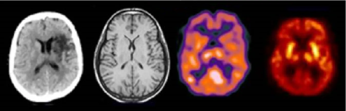
Each type of medical image has its own characteristics [14] and is used for different purposes. Some can be used to view anatomical structures in the body, showing clearly detailed organs or bones, while others allow to show and trace bodily functions or chemical processes, such as blood flowing [15]. Figure 2.1 shows an example of the human brain acquired with different medical imaging types. Due to their popularity, in this work two of the most common volumetric medical imaging types, Magnetic Resonance (MR) imaging and X-ray Computed Tomography (CT), are used.
CT [16] scanners have been available since mid-1970s and were a revolution in medical imaging. Although CT scans use X-rays, they are able to produce images far more
6 Chapter 2. Medical Image Compression
Figure 2.1: Transaxial slice of the human brain acquired with different imaging modalities. From left to right: X-ray Computed Tomography, Magnetic Resonance Imaging, Single-Photon Emission Computed Tomography and Positron Emission Tomography [15].
detailed than conventional X-rays, with the advantage of the scanning speed, since it can be completed in seconds. Despite being capable to show various body parts, such as heart and lungs, the biggest advantage of the CT image is its ability to represent bones, being able to detail even the smallest ones. The use of contrast agents allows the further assessment of blood vessels and organs.
The MR [17] makes use of powerful magnetic fields and radio-frequency pulses, in order to map the internal body structures, with the advantage of this technology not exposing the users to X-rays. MR is mainly used to produce high quality images of soft tissue and anatomic structures, such as grey and white matter in the brain. MR scanners can be used for a wide range of body parts including injuries of the joints, blood vessels, breasts, as well as abdominal and pelvic organs, such as the liver or reproductive organs. Many diseases, such as brain tumours, can be visualized using this type of images because of the high contrast definition, which does not always require contrast agents to produce detailed images of blood vessels.
2.1.2
Tests Dataset
The image dataset used to assess the performance of the proposed predictive scheme is composed of eight volumetric medical images: four CTs and four MRs scans, all available from [18], the image and video repository of the Center for Image Processing (CIPR) of the Rensselaer Polytechnic Institute.
The spatial resolution, bit depth and number of slices of each volume is presented in Table 2.1. These data volumes are sets of spatially adjacent slices, which due to their res-olution and number, as well as bit depth, require a large number of bits to be represented uncompressed.
2.1. Medical Imaging 7
Table 2.1: Medical volumes information.
Sequence Resolution Bit Depth No. Slices
CT_Aperts 256x256 8 97 CT_carotid 256x256 8 74 CT_skull 256x256 8 203 CT_wrist 256x256 8 183 MR_liver_t1 256x256 8 58 MR_liver_t2e1 256x256 8 58 MR_ped_chest 256x256 8 77 MR_sag_head 256x256 8 58
Figure 2.2 shows the midpoint slice of each volume of the dataset. An important charac-teristic of these slices is that since they represent cuts through anatomical organs which extend into the three dimensions, typically neighbouring pixels in adjacent slices are highly correlated. The encoding methods currently recommended by DICOM, which is presented in the following section, do not exploit this correlation to achieve higher compression ra-tios. Therefore it is quite opportune to develop new techniques able to take advantage of the inter-slice correlation characteristics of these volumes, to increase the compression efficiency.
(a) CT_Aperts (b) CT_carotid (c) CT_skull (d) CT_wrist
(e) MR_liver_t1 (f) MR_liver_t2e1 (g) MR_ped_chest (h) MR_sag_head
8 Chapter 2. Medical Image Compression
2.1.3
Digital Imaging and Communications in Medicine (DICOM)
Digital Imaging and Communications in Medicine (DICOM) is the standard for com-munication and management of medical imaging information. Among others, DICOM defines the way devices handle medical data, such as transmission or storage, including for these purposes a protocol for network communications and a file format, in which the file of a medical image contains information about the exam and the patient. DICOM recommended encoders for compression of medical images are JPEG, RLE, JPEG-LS, JPEG2000, MPEG2, H.264/AVC and H.264/AVC Stereo [3].2.2
Lossless Encoders
In this section some of the current state-of-art lossless encoders are described, in order to better understand their compression algorithms.
2.2.1
JPEG2000
JPEG2000 is an image encoding standard [5] based in wavelet transform [19], which aimed to be a more efficient replacement to JPEG. JPEG2000 was designed to be spatially scalable by dividing an image into different sub-bands of frequency, which can be sampled at various resolutions, as can be seen in Figure 2.3.
The block diagram of JPEG2000 algorithm is shown in Figure 2.4. In the first step, each of the image samples is shifted by a DC level, in order for all sample values to be within a dynamic range centred around zero. Then a Multi-Component Transform (MCT) is applied in order to decompose the image in sub-bands, followed by the wavelet transform, with the resulting coefficients being entropically encoded.
The standard allows both lossy and lossless encoding, using a different wavelet transform for each purpose. For lossless encoding, a discrete reversible wavelet transform is used, and the quantization step is bypassed.
Motion JPEG2000
Motion JPEG2000 is an extension of JPEG2000 for video coding, adding support for au-dio. However, it does not perform inter-slice coding, with every frame being independently encoded by JPEG2000.
2.2. Lossless Encoders 9
Figure 2.3: Example of a wavelet transform applied to a slice of CT_skull, obtained with MATLAB.
Figure 2.4: Block diagram of JPEG2000 algorithm [19], for the (a) encoder and (b) decoder.
JP3D
JP3D [9], [20] is an extension of JPEG2000 for volumetric images, such as medical images. In this extension, the tilling of the sequence results in 3D blocks, rather than 2D blocks, which are coded independently. Furthermore, a 3D discrete wavelet transform is applied instead of a 2D transform as used in JPEG2000, allowing decompositions along the three axes, and the entropy encoder is also improved for the 3D blocks.
10 Chapter 2. Medical Image Compression
2.2.2
JPEG-LS
JPEG-LS [4] is a standard for lossless and near-lossless compression of continuous-tone images, which is based on the Low Complexity Lossless Compression for Images (LOCO-I) algorithm. The LOCO-I algorithm consists of three steps, Prediction, Context Modelling and Codification, as detailed in the block diagram of JPEG-LS, shown in Figure 2.5.
Figure 2.5: JPEG-LS block diagram [4].
The prediction step uses a causal template, presented in Figure 2.6, in which x is the current sample and a, b, c and d represent neighbouring pixels. In order to maintain a low complexity algorithm, a simple edge detection method is applied, referred to as Median Edge Detector (MED), which selects a fixed predictor, as represented by Equation 2.1. This predictor tends to choose pixel b when a vertical edge exists, pixel a when a horizontal edge is present and a + b− c if no edge is detected.
Figure 2.6: Causal template used by the MED predictor in JPEG-LS [4].
ˆ xM ED , min(a, b), if c≥ max(a, b) max(a, b), if c≤ min(a, b) a + b− c, otherwise. (2.1)
2.2. Lossless Encoders 11
The next step is the context modelling of the prediction error, where LOCO-I calculates the local gradients in order to determine the context model, followed by the coding of the prediction residue using Golomb-type codes, which allow a symbol-by-symbol coding while preserving a low complexity. In uniform regions, a run-length variation is used instead.
2.2.3
Context based Adaptive Lossless Image Codec (CALIC)
Context based Adaptive Lossless Image Codec (CALIC) [7] is a lossless image encoder, whose algorithm is shown by the flow diagram in Figure 2.7. CALIC is composed by two independent modes: binary and continuous tone.Figure 2.7: Flow diagram of the CALIC algorithm [7].
The binary mode is automatically selected, without explicitly signalling it, when the causal pixel neighbourhood used in the prediction presents only one or two different values. Then, a ternary entropy coder is applied, using one symbol for each different pixel value, and the third one is used as an escape symbol to signal the return to the continuous tone mode. In the continuous tone mode, the Gradient Adaptive Predictor (GAP) is performed, using the causal template shown in Figure 2.8. GAP determines the horizontal and vertical gradients in order to evaluate the orientation and characteristic of the current edge, using predefined thresholds to select whether it is sharp or weak. Then, the predicted value is calculated in accordance to the edge’s attributes, using the corresponding equation from Table 2.2.
12 Chapter 2. Medical Image Compression
Figure 2.8: Causal pixel neighbourhood used by the GAP in CALIC [7]. Table 2.2: Predicted pixel values for each edge type.
Edge Horizontal Vertical
Sharp w n Normal aux + w 2 aux + n 2 Weak 3aux + w 4 3aux + n 4 aux = w + n 2 + ne− nw 4 entropically encoded with an adaptive arithmetic coder.
2.2.4
Multi-scale Multidimensional Parser (MMP)
Multi-scale Multidimensional Parser (MMP) [21–23] is a pattern matching compression algorithm, where the block to encode is matched with known or previously used patterns stored in a dictionary, and the dictionary index of the matched block is coded. One of the advantages of MMP is the use of scale transformations in the stored patterns, in order to allow the matching of blocks with different sizes. MMP has been used for a wide range of applications, including still images, video sequences or stereoscopic images, managing to outperform state-of-the-art encoders. More recently, a lossless version of MMP has been proposed in [24].
The MMP algorithm divides the image to encode into non-overlapping sequential 16×16 blocks, which are encoded in raster scan order, with each block processed individually. The blocks are segmented using a flexible partition scheme, generating an optimized segmentation tree, as shown in Figure 2.9.
Instead of performing pattern matching and directly encoding the image blocks, MMP applies intra prediction techniques, which generate residue patterns with lower energy and with higher probability of existing in the dictionary, thus allowing a more efficient encoding. The prediction modes were adapted from H.264/AVC directional modes for
2.2. Lossless Encoders 13
(a) (b)
Figure 2.9: (a) Flexible segmentation of a block, (b) corresponding segmentation tree [23].
4×4 blocks, with the DC mode being replaced by the Most Frequent Value (MFV) mode. There is also an additional mode based on LSP, which is described in detail in Chapter 5. In order to obtain the optimal segmentation tree, all the prediction modes are tested for every partition, and the resulting residues are coded with MMP. Then, the best prediction mode and partition direction is selected using a rate-distortion optimization function. During the encoding of the image, the used patterns and several variations are added to the dictionary, in order to be reused further in the image.
In the lossless implementation of MMP, the horizontal, vertical and LSP intra prediction modes were enhanced by always using the adjacent pixels in the prediction, instead of using only the ones in the upper or left border of the block. This translates into a Differential Pulse-Code Modulation (DPCM) which allows a more efficient prediction.
3D-MMP
3D-MMP is an extension of the MMP image coder for volumetric images [23, 25]. The first major difference is the use of 3D blocks instead of 2D. Consequently, these blocks can be segmented along three directions, as shown in Figure 2.10, which means that the number of possible block sizes grows considerably, leading to a great increase of the computational complexity. To mitigate this added computational complexity, multiple copies of the patterns in different scales (block sizes) are stored in the dictionary, so as to reduce the number of scale transformations, although this significantly increases the required memory.
In order to take advantage of the inter-slice redundancy present in volumetric images, the intra prediction modes of MMP were adapted for 3D blocks. For LSP, when predicting a pixel, since the previous slice has already been encoded, the causal template includes
14 Chapter 2. Medical Image Compression
Figure 2.10: Triadic flexible partition [23].
pixels of the previous slice, which can belong to the same or a previous block. The H.264/AVC based modes were also extended, using a causal neighbourhood around the 3D block. Besides these adapted modes, in 3D-MMP a new inter-slice prediction mode based on motion estimation was introduced.
For video coding, an hierarchical architecture is used, in which the 3D blocks are generated by grouping the slices alternately, that is, on the temporal axis, the first group of blocks are composed of just odd slices, while the second group contains only even slices, and so forth. This approach, represented in Figure 2.11, is similar to the I/P and B slices compression used on H.264/AVC and HEVC codecs, with the first group of blocks being I/P blocks, and the second B blocks.
This approach allows B blocks to be encoded after the respective I/P blocks. Thus, LSP prediction can be improved for B blocks, since for each slice both the temporally previous and the next slice have been encoded in the I/P block. This way, when coding a pixel in a B block, the pixels used for LSP prediction are the previously coded neighbours of the same slice, and the pixels in the same region from the temporally previous and next slices coded in the preceding I/P block.
2.2.5
Minimum Rate Predictors (MRP)
Minimum Rate Predictors (MRP) [8] is a lossless encoder that uses linear predictors, which are reconfigured for each image to encode. The image is divided into 32×32 size blocks, which can be partitioned, using a quad-tree, down to 2×2 blocks, with the predictors being used in the resulting blocks. Each block is classified in one of M classes, such that
2.2. Lossless Encoders 15
(a)
(b)
Figure 2.11: Video coding architecture in 3D-MMP: a) Sequential and b) Hierarchical [23].
the linear predictors that are used in each block depends on its class.
For a given pixel, p0, the value predicted by the m-th predictor (m = 1, ..., M ) is given
by the Equation 2.2: ˆ s(p0) = K X k=1 am(k)· s(pk), (2.2)
where K is the prediction order, s(pk) is the value of the pk pixel and am(k) is the
respective prediction coefficient. Figure 2.12 shows the distribution of the reference pixels for a prediction order of K = 30. The resulting prediction error is adaptively encoded using context modelling, with the distribution of the prediction errors being estimated by a generalized Gaussian.
Several steps for the optimization of the prediction, the quad-tree and coding information are performed, in order to minimize the cost function for the encoding image. The predic-tion order K and the number of classes M can be determined from the characteristics of the encoding image, so as to use the predictors which best estimate the image structures.
16 Chapter 2. Medical Image Compression
Figure 2.12: Distribution of reference pixels [8].
2.2.6
H.264/Advanced Video Coding (AVC)
H.264/Advanced Video Coding (AVC) is a video coding standard which has a hybrid cod-ing structure [6], [26]. The codcod-ing algorithm, whose block diagram is shown in Figure 2.13, includes the following main steps: intra/inter frame prediction, transform, quantization and entropy coding. Each frame is encoded at the block level, thus each frame is divided into macro-blocks of 16×16 pixels, which can be subsequently segmented. After the intra or inter prediction, a transform (Hadamard or Discrete Cosine Transform (DCT)) is ap-plied to the obtained residue, resulting in a block of coefficients, which are later quantized. Finally, entropy coding is used.
Figure 2.13: Block Diagram of H.264/AVC [6].
2.2. Lossless Encoders 17
I frames, the prediction used is intra-frame only, that is, spatial prediction. The intra prediction modes of H.264/AVC for 4×4 blocks consist of a DC mode and eight directional modes, which are represented in Figure 2.14, while for 16×16 block only 4 modes are available, horizontal, vertical, DC and planar.
Figure 2.14: H.264/AVC Intra prediction directional modes [26].
As for both P and B frames, besides intra prediction, inter-frame prediction with motion compensation can be used, in which pixels from only previous frames or upcoming frames as well, respectively, can be used to predict the current block. For P frames, only one motion vector for a block is transmitted, while for B frames two can be sent, allowing some form of weighted prediction.
This process is lossy, since by using quantization, the information is lost and can’t be recovered in the decoder. Thus, the H.264/AVC standard allows lossless representation of macro-blocks by simply using Pulse Code Modulation (PCM) mode, in which the values of the samples are sent directly without prediction. However, this method is not tuned for efficiency.
Therefore, a more effective lossless coding technique is used: transform-bypass lossless mode. As the name suggests, the transform and the quantization steps are skipped, and only intra prediction and entropy coding are used.
2.2.7
High Efficiency Video Coding (HEVC)
High Efficiency Video Coding (HEVC) [1, 27] is the most recent video coding standard following H.264/AVC, also using a hybrid coding structure. The main difference is the replacement of macro-blocks with Coding Tree Units (CTUs), which can use larger blocks of up to 64×64 pixels, and can also be further partitioned. The use of larger blocks allows the number of intra prediction modes to increase from nine, in the H.264/AVC standard,
18 Chapter 2. Medical Image Compression
to 35, as can be seen in Figure 2.15, and it significantly reduces the bit rate, specially for higher resolution video sequences.
Figure 2.15: HEVC Intra prediction directional modes [1].
Similarly to the H.264/AVC standard, HEVC allows lossless CTU coding in two ways: I_PCM, in which the prediction, transform, quantization, entropy coding and in-loop filtering are not used, and the samples are represented by a fixed number of bits and transmitted directly in the bitstream. And the Lossless mode, in which only the transform, quantization and in-loop filtering are skipped, with the residue resulting from intra and inter prediction being coded entropically, as can be seen in Figure 2.16. The first one can be used to code noise-like signals, and the second one is used to code the remaining signals.
Since the crucial steps of residue transformation and quantization are not used, the com-pression gain is small and the efficiency of prediction methods becomes of utmost impor-tance for the overall encoding performance. Unlike in H.264/AVC, the lossless mode can be used with all the coding structures: Intra, in which all frames are coded using only intra prediction (I frames), Random Access, using both intra and inter prediction (I, P and B frames), and Low Delay, in which only the closest reference images are used for inter prediction (I and B or P frames).
Following the completion of the first edition of the HEVC standard, several additional coding tools were added as part of the Range Extension (RExt) [29]. These extensions include tools to support the encoding of content with higher bit depths and higher chroma-resolution, and a technique for lossless encoding. This technique is based on Differential Pulse-Code Modulation (DPCM) encoding of the residues resulting from intra directional prediction modes. The DPCM encoding of the intra prediction residue, also known as SAP [30], is better suited for lossless encoding since it uses the original pixel values of adjacent neighbours to compute the predicted samples in the current Prediction Unit
2.2. Lossless Encoders 19
Figure 2.16: Block Diagram of HEVC for lossless coding, with dashed lines [28].
(PU), instead of only those in the edge of the PU.
2.2.8
Performance Comparison
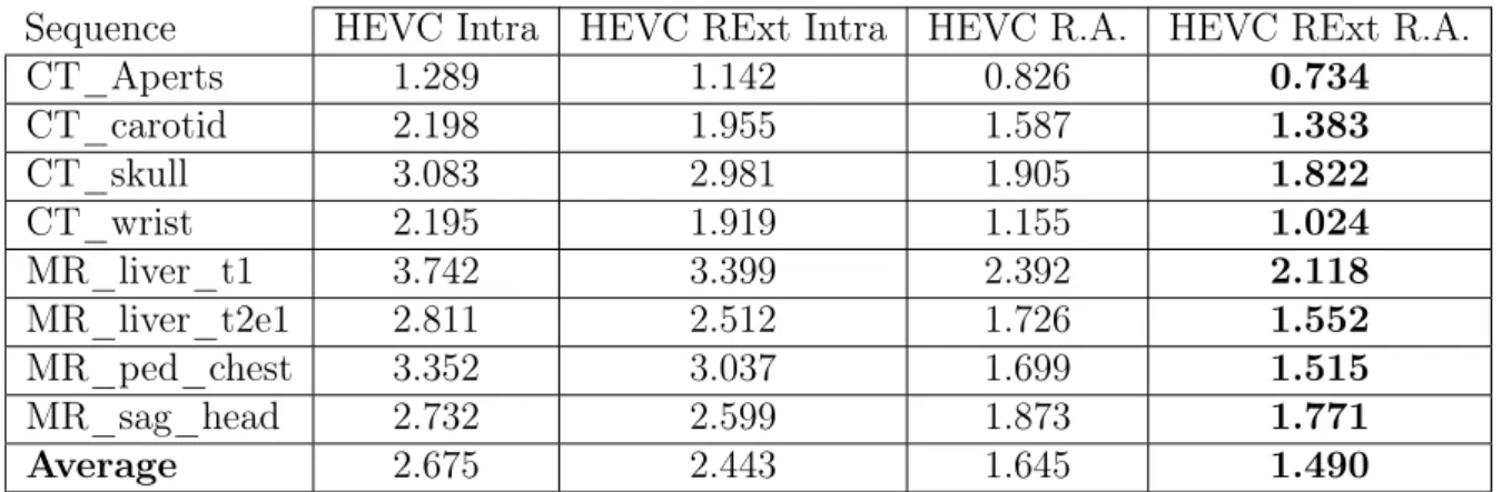
After the study of state-of-the-art lossless encoders, their encoding performance for med-ical images was compared. Publicly available software implementations of JPEG-LS, JPEG2000, JP3D, CALIC, MRP, H.264/AVC and HEVC were used for these tests. Firstly, to evaluate the impact of the RExt in HEVC, the test sequences were encoded using HEVC with and without the RExt profile, for both Intra and R.A. coding structures. The encoding configurations of HEVC were mostly left as default, using the latest release of the reference software HM-16.4. To allow lossless coding, the QP was set to 0, and both TransquantBypassEnableFlag and CUTransquantBypassFlagForce were set to 1. For the RExt profile, the parameter CostMode was set to lossless.
Table 2.3 shows the results, in bits per pixel (bpp), obtained in this test. It can be seen that using inter-slice prediction, such as in Random Access, allows a major bitrate reduction, of 39%, in opposed to Intra only, since it exploits the high inter-slice redundancy present in medical image volumes. As for the use of the RExt profile, for both Intra and Random Access coding structures, there is a performance gain of roughly 9%, which is expected due to the SAP technique, devised specifically for lossless encoding. Given these results, from here forward in this work, every test performed with HEVC includes the
20 Chapter 2. Medical Image Compression
Table 2.3: HEVC performance comparison, with and without Range Extension (RExt) profile (in bits per pixel (bpp)).
Sequence HEVC Intra HEVC RExt Intra HEVC R.A. HEVC RExt R.A.
CT_Aperts 1.289 1.142 0.826 0.734 CT_carotid 2.198 1.955 1.587 1.383 CT_skull 3.083 2.981 1.905 1.822 CT_wrist 2.195 1.919 1.155 1.024 MR_liver_t1 3.742 3.399 2.392 2.118 MR_liver_t2e1 2.811 2.512 1.726 1.552 MR_ped_chest 3.352 3.037 1.699 1.515 MR_sag_head 2.732 2.599 1.873 1.771 Average 2.675 2.443 1.645 1.490 RExt profile.
Table 2.4 presents the lossless compression performance comparison of all the tested en-coders. For H.264/AVC, the latest release of the reference software JM 18.6 was used. For lossless coding, FRExt High 4:4:4 Profile was used for Intra coding, with QP and QP Offsets set to 0. JPEG-LS and CALIC were used with the default configuration for lossless coding. In MRP, the optimization flag was activated, with the remaining options left as default. For JPEG2000, the software implementation OpenJPEG v2.1 is used with the default configuration. This software also includes an implementation of JP3D, which was configured to use a 3D Discrete Wavelet Transform and 3D Embedded Block Coding with Optimal Truncation (EBCOT). As for MMP [24], the fast implementation was used, with the default dictionary size.
Table 2.4: Lossless compression performance comparison of state-of-the-art encoders (in bpp). Sequence H.264 HEVC RExt Intra JPEG 2000 JPEG LS MMP CALIC MRP JP3D HEVC RExt R. A. CT_Aperts 1.193 1.142 1.261 1.058 1.178 0.998 0.775 0.941 0.734 CT_carotid 2.062 1.955 2.019 1.778 1.977 1.684 1.374 1.547 1.383 CT_skull 3.183 2.981 2.991 2.761 2.959 2.628 2.329 2.088 1.822 CT_wrist 1.911 1.919 1.757 1.627 1.717 1.550 1.173 1.238 1.024 MR_liver_t1 3.489 3.399 3.256 3.160 3.393 3.022 2.582 2.356 2.118 MR_liver_t2e1 2.806 2.512 2.572 2.418 2.460 2.269 1.722 1.745 1.552 MR_ped_chest 3.080 3.037 3.021 2.937 3.074 2.789 2.337 2.071 1.515 MR_sag_head 2.635 2.599 2.905 2.582 2.808 2.519 2.279 2.160 1.771 Average 2.545 2.443 2.473 2.290 2.446 2.183 1.821 1.768 1.490
For lossless coding, only JP3D and HEVC R.A. take advantage of the redundancy be-tween slices, while all the other encoders only use intra prediction, being image encoders. As expected, encoders which exploit the inter-slice redundancies generally present better results, with HEVC RExt R.A. obtaining the smallest bitrate on average, with a
consid-2.3. Related State-of-the-Art 21
erable difference over JP3D. As for the image encoders, they present a generally similar performance, with the exceptions of CALIC and more notably MRP, which manages to be close to JP3D, even with only intra prediction.
Another test was performed using 3D-MMP, with block size of 16×16×4. Due to the way it is implemented, the number of slices encoded for each sequence must be multiple of four, in order to segment it into complete blocks. Table 2.5 shows the number of encoded slices for each sequence and the results for 3D-MMP. Although the number of encoded slices is not the same for the other encoders, it differs in only one or two slices, which have an almost negligible effect in the results. When comparing to the other encoders, 3D-MMP has a superior performance to most of the image encoders, but falls short of the video and volumetric encoders HEVC and JP3D, standing somewhat behind MRP. The great disadvantage of 3D-MMP is its unaffordable computational complexity. Given this, and the fact that its results are far from the best, 3D-MMP was not used during the course of this work.
Table 2.5: Lossless encoding results of 3D-MMP (in bpp). Sequence No. Slices 3D-MMP
CT_Aperts 96 0.938 CT_carotid 72 1.622 CT_skull - -CT_wrist - -MR_liver_t1 56 2.579 MR_liver_t2e1 56 2.051 MR_ped_chest 76 1.804 MR_sag_head 56 2.303
2.3
Related State-of-the-Art
In this section, a review of previous work relevant to this dissertation is presented, mainly on two topics: new lossless prediction techniques in HEVC, and lossless encoding methods for medical images.
2.3.1
Lossless Coding in HEVC
With the increasing relevance of screen content coding, the need for more efficient lossless prediction techniques increases, which can be aimed at other applications such as medical imaging. Several techniques for lossless prediction have been proposed in addition to SAP to improve the lossless encoding of HEVC RExt.
22 Chapter 2. Medical Image Compression
The Sample-based Weighted Prediction (SWP), proposed in [31], performs a weighted average of the four causal neighbouring pixels immediately surrounding the current pixel, referred to as a, b, c, d in Figure 2.17, to form its prediction. In order to determine the weights attributed to each pixel, the Sum of Absolute Differences (SAD) is calculated between the patch shown in Figure 2.17 and the same patch placed over each of the neighbouring pixels a, b, c, d. After determining the SAD for each of the four pixels, the corresponding weights are obtained through a look-up table. The SWP replaces the planar mode in HEVC, and presents significant reductions of bitrate when encoding intra only (8.5%), and more modest ones for random access coding structure (2.6%).
Figure 2.17: Sample-based Weighted Prediction (SWP) [32]; Causal neighbourhood used by SWP (left); causal patch placed over pixel to predict X (centre); patch placed over pixel b.
An alternative to SWP is the Directional Template Matching (DTM) [32], which instead of performing a weighted average of the neighbouring pixels, uses directly the one with the highest similarity, that is, the pixel for which the placed patch presents the lowest SAD, thus achieving better reconstruction of sharp edges. The authors also found that using a combination of SWP and DTM provides better prediction performance, by using DTM as an exception algorithm of SWP, with a bitrate reduction of 1.15 percentage points (pp) over just using DTM. Other possible combination is SWP replacing the planar mode and DTM replacing the DC mode, with a bitrate reduction of 2.15 percentage points over just using DTM.
Another method recently proposed is the Sample-based Angular intra-Prediction with Gradient-based (SAP-G) edge prediction [33], which replaces the planar mode. This technique uses the surrounding pixels to compute the gradients in four directions (0 deg., 45 deg., 90 deg. and 135 deg.), as shown in Figure 2.18, and then selects the adjacent neighbouring pixel in the direction of the smallest gradient as the prediction for the current pixel. In addition to this, SAP-G applies the same concept of SAP to the DC mode, computing the average of immediate neighbours of the current pixel instead of the values of the column to the left and the row above the current block. This technique achieves a slight performance improvement (1.05 percentage points) when compared to SWP+DTM method.
2.3. Related State-of-the-Art 23
Figure 2.18: Computing of gradients in four directions in SAP-G [33].
predictor was proposed. In order to improve the prediction of sharp edges, the Median Edge Detector (MED) of JPEG-LS [4] is applied, replacing the planar mode, using the samples b, c and d as shown in Figure 2.19, with the predicted value Px,y given by:
Px,y = min(b, d), if c≥ max(b, d) max(b, d), if c≤ min(b, d) b + d− c, otherwise. (2.3)
Figure 2.19: Prediction principle of SAP [34], where the prediction value is obtained using bilinear interpolation between the immediate neighbours along the prediction direction.
To improve prediction in smooth regions, SAP-ME also introduces a median predictor to replace the DC mode, in which the predicted pixel assumes the value of the median
24 Chapter 2. Medical Image Compression
between the samples a, b, c, d and e, from Figure 2.19, given by Equation 2.4:
Px,y = median{a, b, c, d, e}. (2.4)
SAP-ME is used with SAP as well, and presents an improvement of 1.74 percentage points over the previously described SWP+DTM. All the previously described techniques show that pixel-wise prediction is efficient for lossless compression.
2.3.2
Medical Image Encoding
The growth in the use of medical images led to the need for more efficient compression techniques. More recently, the increasing use of three dimensional medical images, such as CTs and MRs, and even Four-Dimensional (4D) ones, such as functional magnetic resonances, consisting of a sequence of 3D volumes obtained over time, resulted in the development and proposal of several novel methods for their compression.
In [35] a lossless compression technique for 4D medical images using H.264/AVC was proposed. H.264/AVC was modified to just bypass the quantization step, in order to maintain the use of inter prediction. Two methods were proposed, as shown in Figure 2.20, using different coding orders. H.264-VOL encodes each volume separately, with each slice of the volume corresponding to a frame, thus allowing inter-slice prediction between slices of the same volume. As for H.264-TIME, it encodes along the fourth dimension (time), that is, for all the volumes, the slices in the same position are grouped, with each group being encoded independently.
Figure 2.20: Encoding order of 4D medical images using the proposed methods: (a) H.264-VOL and (b) H.264-TIME [35].
2.3. Related State-of-the-Art 25
Comparing to DICOM recommended encoders, both approaches present significant im-provements, however, H.264-TIME achieves a much higher compression ratio, with an increase of almost 70% over previous techniques. This is explained since 4D medical im-ages present the changes of a 3D volume over time, and thus the redundancy between the same slices of the volumes is more significant.
In [36], the same authors propose an improved technique which combines the two methods, as shown in Figure 2.21. Firstly, the motion compensation of H.264-VOL (M C1) is applied, generating residual slices and the respective motion vectors (M VV). Then, the
motion compensation of H.264-TIME (M C2) is applied to the residual slices, with the resulting residue and motion vectors (M VT) being encoded with Context-Adaptive Binary
Arithmetic Coding (CABAC). The motion vectors M VV are differentially coded with a
proposed method and then also encoded with CABAC, incorporating the bitstream. The proposed technique greatly improves, up to three times, the compression ratio of state-of-the-art compression techniques.
Figure 2.21: Block diagram of the proposed technique with H.264/AVC [36].
A new technique for compression of 3D volumetric medical images using linear predic-tion was proposed in [37]. The corresponding block diagram is shown in Figure 2.22. The Medical Images Lossless Compression (MILC) algorithm performs the prediction on a pixel-by-pixel basis, using one of two prediction contexts, depending on whether it is predicting the first slice or not. If it is the first slice, a 2D Linearised Median Predictor (2D-LMP) is used. Similar to the MED predictor of JPEG-LS [4], the three neighbours A, B and C of the current pixel X are used to compute the predicted value ˆX, by per-forming the average of the three possible predictors of MED, resulting in:
ˆ
X = 2× (A + B)
3 −
C
26 Chapter 2. Medical Image Compression
For the remaining slices, since there is at least one previously encoded slice, the 3D Distances-based Linearised Median Predictor (3D-DLMP) is used. In addition to the three neighbouring pixels in the same slice, four collocated pixels A0, B0, C0 and X0 from the previous slice are used for the prediction. Firstly, the differences between the collocated pixels values are computed by δA = A− A0, δB = B− B0 and δC = C− C0. Then, the
optimized approximated difference, or distance, δ is given by:
δ = 2× (δA+ δB)
3 −
δC
3 , (2.6)
similarly to the predictor 2D-LMP. Finally, the predicted value ˆX is computed by adding the determined distance δ to the pixel collocated to the current pixel to predict, given by
ˆ
X = X0+ δ. After obtaining the prediction values, the prediction error is then modelled and coded. The experimental results show that MILC presents a better performance than other state-of-the-art lossless encoders, including CALIC and the DICOM recommended JPEG-LS, reaching a bitrate reduction of 27% and 28%, respectively.
Figure 2.22: Block diagram of the MILC algorithm [37].
A new method for compression of 3D medical images based on their symmetries was proposed in [38] and improved in [39]. As can be seen in the block diagram of Figure 2.23, firstly, a 2D integer wavelet transform is applied to each slice of the volume. Then, an intra-band prediction method based on the symmetry of the sub-band is used, followed by an inter-slice DPCM prediction applied to the resulting residue. The final residue and the prediction parameters are then entropically encoded.
After applying the wavelet transform, in each sub-band the global symmetry axis is de-termined, selecting one of four directions: horizontal, vertical and diagonal up or down. The sub-band is divided into two areas, according to the axis, and partitioned into 16×16
2.3. Related State-of-the-Art 27
blocks. To predict each block, a spatial transformation is applied to previously encoded blocks, and the one which generates the residue with lowest energy is selected. Eight different spatial transformations are tested, including flips and rotations along different directions, which allows to take advantage of local symmetries. Since the blocks are pro-cessed by alternating between both areas of the global symmetry axis, this method also takes advantage of the global symmetry.
Once the intra-band prediction residue is obtained, the inter-slice DPCM method is ap-plied. The residue is divided into 3D blocks, and for each block, DPCM is applied along five directions, with the one generating the lowest energy error being selected. The proposed method achieves a significant compression gain over DICOM recommended encoders, with an average improvement of 17% over JPEG2000 and H.264/AVC intra coding.
Chapter 3
Medical Images Processing
As described in the previous chapter, generally, lossless encoders are not able to exploit the inter-slice redundancy that is present in typical MR and CT images, that are the focus of this work. Thus, in this chapter, several lossless processing techniques are applied to medical image sequences, prior to their encoding. The aim of these techniques is to take advantage of this inter-slice redundancy and improve the compression efficiency.
The following sections describe each technique and present their respective results. Given the characteristic of these techniques, in order to carry out a fair comparison, in this chapter all the tests were performed using a number of slices multiple of 16 in all sequences, as shown in Table 3.1. The performance of all the encoders described in Chapter 2 for these test conditions is presented in Table 3.2.
It can be seen that there are no significant differences over the results with all of the slices, shown in Chapter 2. These results will serve as base of comparison to all the tested approaches.
Table 3.1: Medical volumes with number of slices multiple of 16. Sequence No. Slices Sequence No. Slices
CT_Aperts 96 MR_liver_t1 48
CT_carotid 64 MR_liver_t2e1 48
CT_skull 192 MR_ped_chest 64
30 Chapter 3. Medical Images Processing
Table 3.2: Lossless coding performance comparison for the original sequences with a number of slices multiple of 16 (in bpp).
Sequence H.264 HEVC RExt Intra JPEG 2000 JPEG LS MMP CALIC MRP JP3D HEVC RExt R. A. CT_Aperts 1.200 1.142 1.267 1.064 1.184 1.004 0.776 0.945 0.734 CT_carotid 2.017 1.955 1.981 1.739 1.936 1.647 1.347 1.507 1.383 CT_skull 3.284 2.981 3.079 2.847 3.058 2.713 2.411 2.143 1.822 CT_wrist 1.939 1.919 1.782 1.653 1.743 1.574 1.190 1.261 1.024 MR_liver_t1 3.493 3.399 3.257 3.158 3.383 3.019 2.566 2.409 2.118 MR_liver_t2e1 2.754 2.512 2.530 2.369 2.416 2.223 1.688 1.771 1.552 MR_ped_chest 3.066 3.037 3.015 2.928 3.061 2.780 2.327 2.055 1.515 MR_sag_head 2.639 2.599 2.908 2.585 2.810 2.522 2.281 2.190 1.771 Average 2.549 2.443 2.477 2.293 2.449 2.185 1.823 1.785 1.490
3.1
Concatenated Slices
Despite the main focus of this dissertation being the improvement of HEVC for lossless encoding, a test was performed in order to improve the performance of the lossless en-coders. For instance, MMP is a dictionary-based image encoder in which the previously encoded blocks are stored in a dictionary as patterns, used to predict the following blocks. As such, by concatenating all slices of a sequence side-by-side into a single image, the encoded blocks of previous slices can be used to predict the blocks in the current slice, allowing some form of inter-slice prediction to be used in the image encoders, particularly in MMP.
The achieved results for this approach can be seen in Table 3.3 where all encoders present bitrate reductions, albeit minimal in most cases, with MMP presenting the most significant one as expected, with a reduction of 8.5%, followed by CALIC with 4.6%. Given the large number of slices for the sequences CT_skull and CT_wrist, their respective concatenated images present a very high horizontal resolution, which is not supported in H.264/AVC and JPEG-LS. As such, the results presented in Table 3.3 for these encoders and sequences are the same from encoding the original sequences in Table 3.2, in order to calculate the average and facilitate the comparison.
3.2. Directional Approaches 31
Table 3.3: Encoding results of the concatenated slices (in bpp).
Sequence H.264 HEVC RExt Intra JPEG 2000 JPEG LS MMP CALIC MRP CT_Aperts 1.177 1.136 1.246 1.011 1.017 0.894 0.736 CT_carotid 2.003 1.949 1.955 1.698 1.757 1.548 1.276 CT_skull 3.284 2.973 3.051 2.847 2.882 2.639 2.355 CT_wrist 1.939 1.911 1.757 1.653 1.605 1.492 1.139 MR_liver_t1 3.472 3.393 3.233 3.106 3.146 2.903 2.496 MR_liver_t2e1 2.742 2.504 2.506 2.316 2.197 2.107 1.571 MR_ped_chest 3.040 3.029 3.000 2.873 2.781 2.663 2.264 MR_sag_head 2.618 2.592 2.883 2.534 2.546 2.434 2.243 Average 2.534 2.436 2.454 2.255 2.241 2.085 1.760
3.2
Directional Approaches
Medical images such as CTs and MRs consist of volumes representing a Three-Dimensional (3D) object. These volumes can be observed along different directions, creating slices with varying features, as shown in Figure 3.1. Slices designated by (A) are originally generated in the Z axis, forming a volume from which the slices along X (B) and Y (C) axes are extracted.
The number of slices in the Z axis becomes the width of the slices in the X and Y axes. As some encoders require image dimensions to be multiple of 16, all the tests were performed using a number of slices multiple of 16, as previously stated.
By encoding the volumes along these other directions, different redundancies are exploited by the intra encoders. Tables 3.4 and 3.5 show the compression results for the medical volumes tested along different directions, X and Y, respectively. It can be seen that the image/intra encoders present considerable bitrate reductions, ranging from 14 to 25%
32 Chapter 3. Medical Images Processing
over the encoding in the Z axis, with the slices along X showing a slight advantage. As for video or volumetric encoders, such as HEVC and JP3D, respectively, a significant increase of the bitrate is verified, being around 10% for HEVC and 30% for JP3D. With this improvement, MRP surpasses HEVC and becomes the most efficient encoder for these medical volumes.
This can be explained by the different redundancy levels in slices of each axis. For example, the high redundancy between slices in the Z axis, which is not exploited by the image encoders, is now represented in the X and Y slices, and can thus be an advantage for these encoders. However, for HEVC and JP3D, the inter-slice prediction techniques are the basis for their advantageous performance, while the intra-slice prediction is not as effective, hence obtaining better results when there is more redundancy between slices, as in the Z axis.
Table 3.4: Compression results for slices in the X axis (in bpp).
Sequence H.264 HEVC RExt Intra JPEG 2000 JPEG LS MMP CALIC MRP JP3D HEVC RExt R. A. CT_Aperts 1.074 1.008 1.134 0.937 1.125 0.888 0.676 1.630 0.771 CT_carotid 1.777 1.701 1.723 1.459 1.735 1.458 1.150 1.910 1.424 CT_skull 2.493 2.314 2.227 2.127 2.352 1.970 1.599 2.850 2.038 CT_wrist 1.651 1.602 1.483 1.357 1.460 1.289 0.962 1.734 1.136 MR_liver_t1 3.261 3.106 2.717 2.557 3.128 2.583 2.013 3.161 2.317 MR_liver_t2e1 2.486 2.289 2.059 1.945 2.328 1.944 1.393 2.675 1.889 MR_ped_chest 2.140 2.003 1.966 1.747 2.071 1.712 1.322 2.275 1.713 MR_sag_head 2.417 2.325 2.358 2.059 2.498 2.081 1.687 2.580 2.033 Average 2.162 2.043 1.958 1.773 2.087 1.741 1.350 2.352 1.665
Table 3.5: Compression results for slices in the Y axis (in bpp).
Sequence H.264 HEVC RExt Intra JPEG 2000 JPEG LS MMP CALIC MRP JP3D HEVC RExt R. A. CT_Aperts 1.090 1.037 1.157 0.943 1.113 0.873 0.691 1.572 0.757 CT_carotid 1.792 1.720 1.763 1.530 1.842 1.518 1.231 1.864 1.391 CT_skull 2.517 2.339 2.285 2.198 2.411 2.004 1.639 2.776 2.006 CT_wrist 1.513 1.483 1.259 1.154 1.276 1.112 0.821 1.912 1.209 MR_liver_t1 3.243 3.088 2.705 2.510 3.084 2.535 2.052 3.143 2.335 MR_liver_t2e1 2.568 2.319 2.144 2.053 2.430 2.005 1.642 2.393 1.737 MR_ped_chest 2.198 2.030 2.103 1.844 2.198 1.848 1.460 2.175 1.670 MR_sag_head 2.422 2.335 2.366 2.068 2.522 2.085 1.682 2.590 2.036 Average 2.168 2.044 1.972 1.788 2.110 1.747 1.402 2.303 1.643
3.3. Inter-Slice Prediction 33
3.3
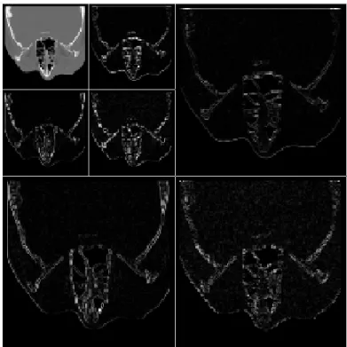
Inter-Slice Prediction
Another approach on the inter-slice redundancy of medical volumes involved the use of inter-slice prediction techniques, with the resulting residue being encoded instead of the original sequences. Firstly, a simple zero-order inter-slice predictor was tested. Due to its promising results, the more complex prediction scheme of HEVC was also tested.
3.3.1
Zero-Order Inter-Slice Predictor
In order to capitalise on the redundancy, a zero-order inter-slice predictor was used, which is translated into a pixel-wise difference between adjacent slices, resulting in a residue that will then be encoded.
This technique is implicit to an extent. Although it is a simple technique that is applied to all the pixels, there may be additional information to transmit to the decoder. That is, when performing a difference operation between two eight bit pixels, the result may have to be represented by a nine bit value, in order to be lossless. In such cases, the pixel value in the residue is truncated to eight bits and the additional information for that pixel is transmitted to the decoder. Given the very low occurrence of this issue, its impact in the final results is insignificant.
Table 3.6 shows the compression results for this technique, implemented along the Z axis. When compared to encoding the original sequences in the same axis, in Table 3.2, the intra/image encoders present very significant gains, with bitrate reductions between 28 and 36%. The encoders with inter-slice prediction, JP3D and HEVC RExt Random Access (R.A.), also present important improvements, although not as accentuated, of approximately 9 and 14%, respectively. With this method, HEVC RExt R.A. achieves the best encoding results, on average, followed closely by the MRP image encoder. Besides the initial Z axis, this technique was also implemented along X and Y axes, whose results are given in Tables 3.7 and 3.8, respectively. Unlike in the Z axis, when compared to their counterparts, this method exhibits much lower gains, being marginal for most encoders, or even losses, as is the case for MRP, JP3D and HEVC RExt R.A.. Thus, encoding the difference residue along the Z axis still yields a large advantage.
Given these results, another test was performed, in which the difference residue obtained along the Z axis is encoded along X and Y directions, achieving the results presented in Tables 3.9 and 3.10. Even though it shows improvements compared to the residue obtained along X and Y axes, there is still a considerable distance to the encoding results of the residue along the Z axis.
34 Chapter 3. Medical Images Processing
Table 3.6: Compression results of the pixel-wise difference residue along the original Z axis (in bpp). Sequence H.264 HEVC RExt Intra JPEG 2000 JPEG LS MMP CALIC MRP JP3D HEVC RExt R. A. CT_Aperts 0.791 0.776 0.933 0.790 0.885 0.771 0.630 0.890 0.679 CT_carotid 1.459 1.442 1.546 1.354 1.500 1.318 1.115 1.380 1.243 CT_skull 2.071 2.045 2.173 2.011 2.141 1.935 1.696 1.924 1.488 CT_wrist 1.115 1.117 1.223 1.049 1.145 1.064 0.862 1.171 0.879 MR_liver_t1 2.216 2.211 2.287 2.098 2.256 2.049 1.790 2.243 1.897 MR_liver_t2e1 1.781 1.774 1.815 1.681 1.714 1.597 1.307 1.632 1.245 MR_ped_chest 1.576 1.580 1.761 1.577 1.696 1.536 1.324 1.785 1.292 MR_sag_head 1.983 1.979 2.177 1.995 2.216 1.975 1.789 2.046 1.538 Average 1.624 1.615 1.739 1.569 1.694 1.531 1.314 1.634 1.282
Table 3.7: Compression results of the pixel-wise difference residue along the X axis (in bpp). Sequence H.264 HEVC RExt Intra JPEG 2000 JPEG LS MMP CALIC MRP JP3D HEVC RExt R. A. CT_Aperts 0.914 0.887 1.053 0.869 1.060 0.872 0.713 1.497 0.823 CT_carotid 1.608 1.580 1.637 1.399 1.678 1.417 1.194 1.935 1.506 CT_skull 2.330 2.294 2.218 2.157 2.353 2.012 1.729 2.909 2.205 CT_wrist 1.171 1.160 1.276 1.094 1.278 1.125 0.907 1.601 1.116 MR_liver_t1 2.631 2.522 2.543 2.323 2.832 2.361 2.031 3.041 2.409 MR_liver_t2e1 2.128 2.047 1.957 1.834 2.135 1.811 1.411 2.610 1.989 MR_ped_chest 2.053 1.924 2.131 1.867 2.236 1.893 1.590 2.550 1.901 MR_sag_head 2.407 2.327 2.540 2.260 2.706 2.288 1.946 2.757 2.288 Average 1.905 1.843 1.920 1.725 2.035 1.722 1.440 2.363 1.780
Table 3.8: Compression results of the pixel-wise difference residue along the Y axis (in bpp). Sequence H.264 HEVC RExt Intra JPEG 2000 JPEG LS MMP CALIC MRP JP3D HEVC RExt R. A. CT_Aperts 0.908 0.888 1.059 0.868 1.021 0.845 0.714 1.419 0.826 CT_carotid 1.541 1.513 1.622 1.395 1.677 1.401 1.194 1.858 1.424 CT_skull 2.252 2.215 2.201 2.127 2.323 1.976 1.715 2.794 2.127 CT_wrist 1.325 1.321 1.267 1.129 1.299 1.124 0.921 1.879 1.268 MR_liver_t1 2.641 2.537 2.563 2.321 2.826 2.355 2.064 3.015 2.395 MR_liver_t2e1 1.973 1.903 1.919 1.795 2.107 1.752 1.527 2.213 1.695 MR_ped_chest 1.930 1.796 2.122 1.820 2.185 1.872 1.591 2.348 1.748 MR_sag_head 2.407 2.324 2.540 2.265 2.693 2.286 1.939 2.757 2.288 Average 1.872 1.812 1.912 1.715 2.016 1.701 1.458 2.285 1.721

![Figure 2.7: Flow diagram of the CALIC algorithm [7].](https://thumb-eu.123doks.com/thumbv2/123dok_br/18396762.893671/33.892.209.735.447.817/figure-flow-diagram-calic-algorithm.webp)
![Figure 2.10: Triadic flexible partition [23].](https://thumb-eu.123doks.com/thumbv2/123dok_br/18396762.893671/36.892.221.620.114.428/figure-triadic-flexible-partition.webp)
![Figure 2.13: Block Diagram of H.264/AVC [6].](https://thumb-eu.123doks.com/thumbv2/123dok_br/18396762.893671/38.892.97.747.710.1072/figure-block-diagram-of-h-avc.webp)
![Figure 2.16: Block Diagram of HEVC for lossless coding, with dashed lines [28].](https://thumb-eu.123doks.com/thumbv2/123dok_br/18396762.893671/41.892.151.789.114.506/figure-block-diagram-hevc-lossless-coding-dashed-lines.webp)
![Figure 2.18: Computing of gradients in four directions in SAP-G [33].](https://thumb-eu.123doks.com/thumbv2/123dok_br/18396762.893671/45.892.241.705.109.354/figure-computing-gradients-directions-sap-g.webp)
![Figure 2.20: Encoding order of 4D medical images using the proposed methods: (a) H.264-VOL and (b) H.264-TIME [35].](https://thumb-eu.123doks.com/thumbv2/123dok_br/18396762.893671/46.892.89.754.811.1098/figure-encoding-order-medical-images-using-proposed-methods.webp)