Setembro, 2016
Frederico José Bessa Dutra
Licenciatura em Ciências da Engenharia Mecânica
TRIZ Methodology Applied to Maintenance
Problem Solving on Industrial Steam
Systems in Africa
Dissertação para obtenção do Grau de Mestre em Engenharia Mecânica
Orientadora: Prof.ª Doutora Helena Victorovna Guitiss Navas, Prof.ª Auxiliar, FCT-UNL
Co-orientador: Eng.º João André Alves Ribeiro, Business Developer Manager, Bosch Termotecnologia, S.A.
Júri:
Presidente: Vogais:
Prof. Doutor Daniel Cardoso Vaz
I
TRIZ Methodology Applied to Maintenance
Problem Solving on Industrial Steam
Systems in Africa
Copyright © 2016, Frederico José Bessa Dutra, Faculdade de Ciências e Tecnolo-gia, Universidade Nova de Lisboa.
III
Acknowledgments
I want to express my truly thanks to Eng. João Ribeiro, for his guidance during the work and for his support throughout the whole process.
To Professor Helena Navas I’m grateful for the availability and interest in guid-ing the present dissertation, as well as her constant concern with its development.
Mostly, I want to thank and dedicate this work to my family for their constant, concrete and unwearying help during my entire life. Without them the development of this work would not be possible, because despite the distance, with love and affection they have always given me courage, strength and confidence to never give up. In partic-ular, want to thank my parents for all the sacrifices they made over the past years, all the support and understanding they gave me in difficult times. To my brothers I thank all the understanding for being away, they were just kids when I left, now they are teenag-ers.
Finally, I want to thank Mónica the understanding for the days I could not be present. Thank you for all the support and motivation in the most difficult times during my degree, without you I would not be able to do it. Thank you for being yourself, for your patience, companionship, trust, understanding, love, care and the power you trans-mitted.
V
Abstract
The problems in steam systems installations in Africa have three main causes: lack of proper preventive and predictive maintenance actions; lack of awareness of the importance of availability and efficiency of the systems during design stage; and lack of care and misuse of the steam systems during operation due to the scarcity of specialized workforce.
The present study, carried out during a one year trainee program within the scope of Bosch Industrial Business Development in Africa, is focused on identifying po-tential improvement points and problems related to maintenance and efficiency in Steam Systems in Africa. Maintenance services offered by the company were studied and after thorough analysis, improvement points were identified using TRIZ methodol-ogy in order to propose enhanced solutions further adapted to the African necessities. A detailed analysis was performed regarding the problems of equipment availability in Africa, thus enlightening the importance of redundant solutions in a market where qual-ified workforce and spare parts for equipment are not easily and readily available.
A remote predictive and preventive maintenance solution was identified using Contradiction Matrix. An improvement to a maintenance contract was proposed using Substance-Field analysis. A suggestion to increase the availability of a steam system, and a proposal to increase the efficiency of a steam system were both also developed using Substance-Field analysis.
In this way, the study was focused on using innovative methodologies in the development of improvement proposals in Africa, without disregarding the importance of certain aspects that are often not taken into account as much as they should.
VII
Resumo
Os problemas em sistemas de vapor instalados em África têm três causas princi-pais: falta de ações de manutenção preventiva e preditiva adequadas; falta de sensibili-zação para a importância da disponibilidade e eficiência dos sistemas durante a fase de projeto dos mesmos; e falta de cuidado e má utilização dos sistemas de vapor durante a operação devido à escassez de mão-de-obra especializada.
O presente estudo, realizado durante um programa de estágio com duração de um ano no âmbito do Desenvolvimento de Negócio da Bosch Industrial em África, fo-cou-se na identificação de potenciais pontos de melhoria e problemas relacionados com manutenção e eficiência em Sistemas de Vapor em África. Os serviços de manutenção oferecidos pela empresa foram estudados e após uma sucinta análise, pontos de melho-ria foram identificados utilizando a metodologia TRIZ de modo a propor soluções aper-feiçoadas e adaptadas às necessidades Africanas. Foi efetuada uma análise detalhada em relação aos problemas de disponibilidade dos equipamentos em África, sublinhando-se a importância de soluções redundantes num mercado onde mão-de-obra qualificada e peças de reserva para os equipamentos não são de fácil e imediata disponibilidade.
Uma solução de manutenção preditiva remota foi identificada através da utiliza-ção da Matriz de Contradições. Uma melhoria ao contrato de manutenutiliza-ção, uma sugestão para o aumento da disponibilidade de um sistema de vapor, e ainda uma proposta para o aumento da eficiência de um sistema de vapor, foram propostos através da aplicação da análise Substância-Campo.
Desta forma, o estudo focou-se no uso de metodologias inovadoras no desenvol-vimento de propostas de melhoria para sistemas de vapor em África, sem desconsiderar a importância de certos aspetos que muitas vezes são menosprezados.
IX
Contents
1 INTRODUCTION ... 1
1.1 MOTIVATION ... 1
1.2 OBJECTIVES ... 2
1.3 OUTLINE ... 2
2 TRIZ METHODOLOGY ... 5
2.1 A DESCRIPTION OF TRIZ ... 5
2.2 FUNDAMENTAL CONCEPTS OF TRIZ ... 6
2.2.1 Ideality ... 6
2.2.2 Contradiction ... 7
2.2.3 Evolution Patterns ... 8
2.3 TRIZ TECHNIQUES AND PRINCIPLES OF APPLICATION ... 9
2.3.1 Substance-Field Analysis ... 9
2.3.2 Inventive Principles and Contradiction Matrix ... 15
2.3.3 Algorithm of Inventive Problem Solving (ARIZ) ... 17
3 INDUSTRIAL MAINTENANCE ... 19
3.1 HISTORICAL EVOLUTION OF MAINTENANCE ... 19
3.2 THE CONCEPT OF MAINTENANCE ... 21
3.3 TYPES OF MAINTENANCE ... 22
3.4 AVAILABILITY ... 26
3.5 OTHER APPROACHES ... 28
4 STEAM SYSTEMS INSTALLATION AND MAINTENANCE ... 33
4.1 HISTORICAL EVOLUTION OF STEAM SYSTEMS ... 33
4.2 INTRODUCTION TO STEAM SYSTEMS ... 34
4.3 INDUSTRIAL STEAM BOILERS ... 36
4.4 STEAM DISTRIBUTION SYSTEMS ... 38
4.4.1 Condensate Recovery System ... 39
4.5 STEAM SYSTEM MAINTENANCE ... 42
4.6 INSTALLATIONS BEST PRACTICES ... 44
X
5 ANALYSIS OF CURRENT MAINTENANCE SERVICES OFFERED BY THE COMPANY IN AFRICA ... 55
5.1 COMPANY CHARACTERIZATION ... 55
5.1.1 Company History ... 56
5.1.2 Main Products ... 57
5.2 MAINTENANCE SERVICES AND ACTIVITIES ... 58
5.2.1 Identified Improvement Aspects ... 60
6 DEVELOPMENT OF IMPROVEMENT PROPOSALS ... 65
6.1 REMOTE PREDICTIVE MAINTENANCE SOLUTION ... 65
6.2 MAINTENANCE CONTRACT IMPROVEMENT ... 73
6.3 SYSTEM AVAILABILITY IMPROVEMENT ... 75
6.4 SYSTEM EFFICIENCY IMPROVEMENT ... 77
7 CONCLUSIONS AND FUTURE DEVELOPMENTS ... 81
BIBLIOGRAPHY ... 85
COMPLEMENTARY BIBLIOGRAPHY ... 91
APPENDIX ... 93
APPENDIX A ……….95
APPENDIX B ……….98
XI
Figure Index
FIGURE 1.1 DISSERTATION STRUCTURE... 3
FIGURE 2.1 STEPS USED BY TRIZ FOR PROBLEM SOLVING ... 6
FIGURE 2.2 TYPES OF CONTRADICTIONS ... 8
FIGURE 2.3 CONNECTION BETWEEN FIELD AND SUBSTANCES ... 10
FIGURE 2.4 PROBLEMATIC SITUATION 1 ... 12
FIGURE 2.5 PROBLEMATIC SITUATION 2 ... 12
FIGURE 2.6 PROBLEMATIC SITUATION 3 ... 12
FIGURE 2.7 GENERAL SOLUTION 1 ... 13
FIGURE 2.8 GENERAL SOLUTION 2 ... 13
FIGURE 2.9 GENERAL SOLUTION 3 ... 13
FIGURE 2.10 GENERAL SOLUTION 4 ... 14
FIGURE 2.11 GENERAL SOLUTION 5 ... 14
FIGURE 2.12 GENERAL SOLUTION 6 ... 14
FIGURE 2.13 GENERAL SOLUTION 7 ... 15
FIGURE 2.14 ARIZ FLOWCHART ... 17
FIGURE 3.1 TEMPORAL EVOLUTION OF MAINTENANCE ... 20
FIGURE 3.2 THE IMPORTANCE OF MAINTENANCE IN THE PRODUCTION PROCESS ... 22
FIGURE 3.3 DIFFERENT TYPES OF MAINTENANCE ... 22
FIGURE 4.1 STEAM SYSTEM SCHEME ... 35
FIGURE 4.2 SECTIONAL DRAWING OF A THREE PASS BOILER ... 37
FIGURE 4.3 STEAM DISTRIBUTION SYSTEM [47]... 38
FIGURE 4.4 BOSCH CONDENSATE SERVICE MODULE ... 41
FIGURE 4.5 CORRECT STEAM OFF-TAKE ... 45
FIGURE 4.6 AIR VENTING AND STEAM TRAP AT THE END OF A STEAM MAIN ... 46
FIGURE 4.7 FLASH STEAM VESSEL OPERATION [55] ... 49
FIGURE 4.8 FORMATION OF A CONDENSATE SLUG ... 52
FIGURE 5.1 BOSCH BOILERS PORTFOLIO ... 57
FIGURE 5.2 BOSCH MANAGEMENT SYSTEM FOR THE CONTROL OF STEAM SYSTEMS ... 59
FIGURE 5.3 BURNER MIXING HEAD WITHOUT PROPER MAINTENANCE ... 62
FIGURE 5.4 BURNER MIXING HEAD AFTER MAINTENANCE WORK ... 62
FIGURE 5.5 FLAME TUBES WITHOUT PROPER MAINTENANCE ... 63
XII
FIGURE 6.1 CONTRADICTION MATRIX FOR CASE A ... 66
FIGURE 6.2 MAIN MENU OF THE EXISTING CRM ... 67
FIGURE 6.3 BOILER INVENTORY SECTION OF THE EXISTING CRM ... 68
FIGURE 6.4 VISITS REPORT SECTION OF THE EXISTING CRM ... 69
FIGURE 6.5 IMPROVEMENT SUGGESTION FOR THE MAIN MENU OF THE CRM ... 70
FIGURE 6.6 IMPROVEMENT SUGGESTION FOR THE VISITS SECTION OF THE CRM ... 71
FIGURE 6.7 IMPROVEMENT SUGGESTION FOR THE BOILER INVENTORY SECTION OF THE CRM ... 72
FIGURE 6.8 LINES HIGHLIGHTED WHEN A PREDETERMINED LIFETIME IS REACHED. ... 72
FIGURE 6.9 PROBLEMATIC SITUATION 3 – INSUFFICIENT OR INEFFICIENT IMPACT BETWEEN THE SUBSTANCES ... 74
FIGURE 6.10 GENERAL SOLUTION 4 FOR PROBLEMATIC SITUATION 3 ... 74
FIGURE 6.11 PROBLEMATIC SITUATION 2 – HARMFUL INTERACTION BETWEEN THE SUBSTANCES ... 76
FIGURE 6.12 GENERAL SOLUTION 6 FOR THE PROBLEMATIC SITUATION ... 77
FIGURE 6.13 GENERAL SOLUTION 4 FOR THE PROBLEMATIC SITUATION ... 78
FIGURE 6.14 GENERAL SOLUTION 7 FOR PROBLEMATIC SITUATION 3 ... 79
XIII
Table Index
TABLE 2.1 SYMBOLOGY USED IN SUBSTANCE-FIELD DIAGRAMS ... 10
TABLE 2.2 SUBSTANCE-FIELD STANDARD SOLUTIONS ... 11
TABLE 2.3 ENGINEERING FEATURE ... 15
TABLE 2.4 INVENTIVENESS PRINCIPLES ... 16
TABLE 3.1 BENEFITS OF USING TPM ... 29
TABLE 5.1 BOSCH PRODUCT PORTFOLIO FOR BOILER HOUSE COMPONENTS ... 58
APPENDIX TABLE A.1 CONTRADICTION MATRIX ... 95
XV
Abbreviations and Symbology
AA Achieved Availability
AI Inherent Availability
AO Operational Availability
API American Petroleum Institute
ARIZ Algorithm for Inventive Problem Solving BTU British Thermal Unit
CBM Condition Based Maintenance CIWH Condensate Induced Water Hammer
CM Condition Monitoring
CRM Customer Relationship Management
IoT Internet of Things
LDI Liquid Droplet Impingement
M̅ Mean maintenance downtime
MAWP Maximum Allowable Working Pressure MTBF Mean Time Between Failures
MTBM Mean Time Between Maintenance
MTTR Mean Time To Repair
NB National Board of Boiler and Pressure Vessel Inspectors OPE Overall Plant Efficiency
PED Pressure Equipment Directive
PM Preventive Maintenance
XVI
SWP Safe Working Pressure
1
1.1
Motivation
Business is progressively becoming more complex and competitive. For compa-nies to thrive in such environment a combination between innovation and maintenance is crucial. Every equipment, especially in the industry, needs maintenance actions in or-der to ensure its operability, reliability and safety. Proper maintenance actions and sys-tematic innovation can be the perfect combination for success. One methodology able to transform innovation into a reliable tool is the Theory of Inventive Problem Solving (TRIZ).
During a one year trainee program in Bosch, it was possible to note that certain maintenance services provided to Africa offered the possibility to be further adapted to the market. After a comprehensive examination of the issues with equipment availabil-ity, it was evident the importance of redundant solutions in a market where there is an absence of qualified workforce and spare parts.
2
1.2
Objectives
The objective of this dissertation is the development of improvement proposals for the problems identified throughout the trainee program in Bosch. For the develop-ment of this proposals, it is presented the use of a reliable and innovative approach in order to create solutions based on logic and data in a systematic way that can be used repeatedly and consistently to quicken the ability of teams to solve problems.
TRIZ methodology offers several tools that can be used in order to create im-provement solutions. As such, Contradiction Matrix, one of the tools of TRIZ methodol-ogy, is used to determine a remote predictive and preventive maintenance solution with the objective of obtaining a method to perform additional actions remotely, which is one of the most efficient ways to provide a specialized service to very large and spread re-gions as is the case in Africa.
Substance-Field analysis, another tool of TRIZ methodology is used with the ob-jective of identifying problematic situations in the existent maintenance contract and cre-ate specific solutions by analyzing the general solutions for those problematic situations.
Substance-Field analysis is also used in order to show how system availability can be improved with the addition of supplementary stand-by equipment that provides a higher degree of redundancy to the system. At last, it is used with the purpose of cre-ating specific solutions for the efficiency improvement of a steam system, by analyzing the general solutions proposed by the tool for the problematic situations identified in that particular scenario.
1.3
Outline
The structure of this dissertation is divided in 7 different chapters, from the
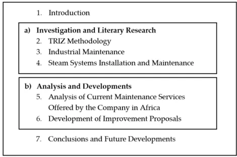
“In-troduction” to the “Conclusion and Future Developments”. These chapters are repre-sented in Figure 1.1 where two main blocks can be distinguished:
3 Block b) represents the analysis and developments performed.
Figure 1.1 Dissertation Structure
In this first chapter, an introduction is made to the addressed subject, as well as the contribute of the work and its objectives. A brief description of each chapter of the dissertation is also presented.
In chapter 2 the theoretical concepts of TRIZ Methodology are covered. The methodology is described and the fundamental principles reviewed. The main tech-niques intrinsic to TRIZ are specified with a focus on the Contradiction Matrix and Sub-stance-Field Analysis which will be used more in depth in this dissertation.
Chapter 3 addresses the theoretical aspects of Maintenance. Besides reviewing the concept, also the different types of Maintenance are mentioned with a focus on the topics discussed further on this dissertation.
4
In chapter 5, current maintenance services offered by the studied company are analyzed. Main emphasis is given to preventive and predictive maintenance services offered. Subsequently, the improvement aspects that were identified are described.
In chapter 6, improvement proposals are developed using the tools that were reviewed in the previous chapters. TRIZ methodology tools, namely, Contradiction Ma-trix and Substance-Field Analysis are used together with maintenance concepts in order to develop solutions.
5 Business is progressively becoming more complex and competitive. For compa-nies to thrive in this environment, innovation is crucial. However, in order to achieve reliable results, innovation cannot be seen as a product of sporadic inspiration, but in-stead, as a product of systematic learning and management capacity.
Systematic innovation is a concept that uses predefined inventive tools to reliably generate new ideas, and incorporate them into new products and processes. The use of systematic innovation increases design effectiveness, enhancing competitiveness and profitability. One method able to transform innovation into a reliable approach is TRIZ [1].
2.1
A Description of TRIZ
TRIZ, a Russian acronym for “Theory of Inventive Problem Solving”, is a
pre-dictable problem solving method invented between 1946 and 1985 in the former U.S.S.R by G.S. Altshuller and his colleagues. A methodology based on logic and data that quick-ens the ability of project teams to solve project related problems, which uses an algorith-mic and structural approach to study problem patterns and solutions.
From project management to six sigma projects, the application of TRIZ method-ology in the resolution of problems is becoming widely common in the industry.
6
about this methodology was the principle that for any given problem, somebody some-where had already solved that problem or one very similar to it. So finding that solution and adapting it to that particular problem was considered a reliable and repeatable cre-ativity process. Figure 2.1 shows the problem solving steps used by TRIZ [2], [3].
Figure 2.1 Steps used by TRIZ for problem solving [1]
2.2
Fundamental Concepts of TRIZ
2.2.1
Ideality
TRIZ ideology is based in two major ideas: Ideality and Contradiction. Ideality can be defined as the subject of creating ideal objects that represent the limit of real ob-jects. Such objects cannot exist in reality and cannot be obtained as a result of any exper-iment. As so, ideality is an abstraction that represents the reflections of reality, useful for the studies of various phenomena [4].
7 In TRIZ, ideality can be applied to define different ideal categories that represent the boundaries of what can be achieved in reality. Such categories include [4]:
The Ideal Process: which is the process result without the process itself; The Ideal Method: which expend no energy or time but obtains the
nec-essary effect;
The Ideal Machine: which has no mass or volume but can accomplish the required work;
The Ideal Substance: which is actually no substance, but whose function is performed;
The Ideal Technique: which occupies no space, has no weight, requires no labor or maintenance, and delivers the benefit without the harm, with-out any additional energy, mechanisms, cost or raw material.
By analyzing the description of each bullet, one can confirm that an ideal system is something unrealistic. However, ideality can be used to improve existent systems and make them closer to the ideal solution. In order to expand Ideality of a system, one should increase benefits and/or decrease expenses and/or decrease harm.
The level if ideality can be calculated as follows:
Ideality = ∑(Harmful Functions + Costs)∑ Useful Functions (1)
2.2.2
Contradiction
8
Usually, when the contradictions existent in a problem are not overcome, the problem is not solved. In order to find creative and effective solutions for the problem, the solver must extract its contradictions. Figure 2.2 shows a detailed scheme of different types of contradictions.
Figure 2.2 Types of contradictions (adapted from [4])
During the resolution of a problem in the framework of TRIZ, there is consecu-tive reformulation of contradictions generated by the problem. Each successive
contra-diction improves the solver’s understanding of said problem.
2.2.3
Evolution Patterns
Through an extensive analysis of patents, Genrich Altshuller and its colleagues found that technological systems often followed regularities during their evolution pro-cess. Altshuller identified those regularities and established eight patterns of technical systems evolution used in the resolution of complex problems and in the prediction of future evolution of techniques [6]. The eight established patterns are [7]:
9 3. Uneven development of subsystems resulting in contradictions; 4. Increasing dynamism and controllability;
5. Increasing complexity, followed by simplicity through integration; 6. Matching and mismatching of parts;
7. Transition from macrosystems to microsystems using energy fields to achieve better performance or control;
8. Decreasing human involvement with increasing automation.
2.3
TRIZ Techniques and Principles of Application
2.3.1
Substance-Field Analysis
Substance-Field analysis (also known as SuField analysis) is one of TRIZ analyt-ical tools and is considered a useful tool to identify problems and find solutions. This analysis has the capacity to modulate a technological system with simple graphic sym-bology of easy interpretation [6].
Functions performed by technological systems can be viewed as transformations of various types of energy and substances. A process performed by a technological sys-tem should involve at least three components; a tool, an article and a field source; which are described in TRIZ as substances and fields [6].
In TRIZ, the term “substance” can be a technological system of various degrees
of complexity. The term “field” refers to the energy needed for interaction/control of
two substances. These can be physical fields and engineering fields [8].
10
identifying what needs to be changed or improved [1]. These lines are represented on Table 2.1.
Table 2.1 Symbology used in Substance-Field diagrams [9]
Symbol Effect
Desired action or effect
Insufficient or inefficient action or effect Harmful action or effect
There are five major types of relationships between substances [1]: 1. Useful impact;
2. Harmful impact; 3. Excessive impact; 4. Insufficient impact; 5. Transformation.
Once identified the type of problem, a standard solution can be selected and ap-plied to that specific problem in order to improve it. This action is done by changing, removing or adding substances or fields [1].
The model of a minimal technological system is represented by two substances
S1 and S2 and a field F, as represented in Figure 2.3.
Figure 2.3 Connection between field and substances [8]
11 The process of functional model construction follows the subsequent stages [1]:
1. Survey of available information;
2. Construction of Substance-Field diagram; 3. Identification of problematic situation;
4. Selection of a general solution (standard solution); 5. Development of a specific solution for the problem.
Substance can be defined as any object, independent of its complexity, and is represented as S. Substance S1 is the article changed, repaired, transformed, discovered,
inspected, etc. And substance S2, known as tool, is the action that needs to be performed.
The field F supplies the force and energy that ensures the action from S2 to S1. These
three interactive agents are necessary and sufficient to achieve the necessary solution for the problem [9].
The Substance-Field analysis tool uses 76 standard solutions which are described in Appendix B. Developed by G.S. Altshuller and his associates between 1975 and 1985, these solutions were grouped into five large categories as shown below, in Table 2.2 [10]:
Table 2.2 Substance-Field standard solutions
Category
Number Solution Category
Number of Standard Solutions
1 Construct or destroy a substance-field 13
2 Develop a substance-field 23
3 Transition from a base system to a
super-system or to a subsuper-system 6
4 Measure or detect anything within a technical
system 17
5 Introduce substances or fields into a technical
system 17
Total 76
12
Problematic Situation 1 (Figure 2.4) - Incomplete model. It is necessary to com-plete the model by adding a field.
Figure 2.4 Problematic situation 1 [1]
Problematic Situation 2 (Figure 2.5) - Complete model with harmful interactions between the substances. There is a negative effect that needs to be eliminated. This can be done by modifying the field or adding an additional one.
Figure 2.5 Problematic situation 2 [1]
Problematic Situation 3 (Figure 2.6) - Complete model with insufficient or ineffi-cient impact between the substances. It is necessary to improve the model by modifying S1, S2, F, or by adding a new substance to achieve the necessary action.
Figure 2.6 Problematic situation 3 [1]
13 General Solution 1 (Figure 2.7) - Complete an incomplete Substance-Field model.
Figure 2.7 General solution 1 [1]
General Solution 2 (Figure 2.8) - Modifying substance S1 to eliminate or reduce
the negative impact or to produce or improve the positive impact.
Figure 2.8 General solution 2 [1]
General Solution 3 (Figure 2.9) - Modifying substance S2 to eliminate or reduce
the negative impact or to produce or improve the positive impact.
Figure 2.9 General solution 3 [1]
14
Figure 2.10 General solution 4 [1]
General Solution 5 (Figure 2.11) - Eliminate, neutralize or isolate the negative im-pact using another field Fx that interacts with the system.
Figure 2.11 General solution 5 [1]
General Solution 6 (Figure 2.12) - Introduce a new positive field in the model.
Figure 2.12 General solution 6 [1]
15 Figure 2.13 General solution 7 [1]
2.3.2
Inventive Principles and Contradiction Matrix
Upon a deep analysis work to a vast amount of patents done by Altshuller, it was possible to create a contradiction matrix that solves many of the technical problems en-countered today [12].
This contradiction matrix is one of the most used tools by TRIZ users. It consists in 39 engineering parameters, represented in Table 2.3 and 40 inventive principles, rep-resented in Table 2.4 which can be chosen in accordance with their applicability to the studied conflict [11].
Table 2.3 Engineering Feature [13]
Nº Engineer Feature Nº Engineer Feature
1 Weight of moving object 21 Power
2 Weight of stationary 22 Loss of energy 3 Length of moving object 23 Loss of substance 4 Length of stationary object 24 Loss of information 5 Area of moving object 25 Loss of time
6 Area of stationary 26 Quantity of substance 7 Volume of moving object 27 Reliability
8 Volume of stationary 28 Measurement accuracy 9 Speed 29 Manufacturing precision 10 Force (Intensity) 30 Object-affected harmful 11 Stress of pressure 31 Object-generated harmful 12 Shape 32 Ease of manufacture 13 Stability of the object 33 Ease of operation 14 Strength 34 Ease of repair
15 Durability of moving obj. 35 Adaptability or versatility 16 Durability of non-moving obj. 36 Device complexity 17 Temperature 37 Difficult of detecting 18 Illumination intensity 38 Extent of automation 19 Use of energy by moving 39 Productivity
16
Table 2.4 Inventiveness Principles [14]
Nº Inventiveness Principle Nº Inventiveness Principle
1 Segmentation 21 Skipping
2 Taking out 22 Turning loss into profit 3 Local quality 23 Feedback
4 Asymmetry 24 Intermediary 5 Merging 25 Self-service 6 Universality 26 Copying
7 Nested doll 27 Cheap short-living objects 8 Anti-weight 28 Mechanics substitution 9 Preliminary anti-action 29 Pneumatics and hydraulics 10 Preliminary action 30 Flexible shells and thin films 11 Beforehand cushioning 31 Porous materials
12 Equipotentiality 32 Color changes 13 The other way around 33 Homogeneity
14 Spheroidality - Curvature 34 Discarding and recovering 15 Dynamics 35 Parameter changes
16 Partial or excessive actions 36 Phase transitions 17 Another dimension 37 Thermal expansion 18 Mechanical vibration 38 Strong oxidants 19 Periodic action 39 Inert atmosphere 20 Continuity of useful action 40 Composite materials
In order to solve a conflict using the contradiction matrix, a statement of the prob-lem must be drawn so that the contradictions contained in the system can be revealed. Then the parameters that affect and improve the performance of the system must be identified [1].
17
2.3.3
Algorithm of Inventive Problem Solving (ARIZ)
ARIZ is the Russian acronym for Algorithm of Inventive Problem Solving and is the main analytical solution tool of TRIZ. The conventional approach to a creative prob-lem implies a search for a solution to the probprob-lem. In the TRIZ approach the probprob-lem- problem-solving as a procedure of seeking solution is replaced with a process of problem refor-mulation.
The concept of consecutive reformulations of the initial problem is realized in ARIZ, which is a set of successive logical procedures directed at reinterpretation of a given problem through two different concepts: System Conflict and Ideality, as seen in Figure 2.14.
Figure 2.14 ARIZ flowchart (adapted from [16])
ARIZ defines the ideal final result and identifies the contradictions. Usually, to realize the Ideal Final Result, the critical component of the system in the Conflict Domain must possess contradictory physical properties.
18
1. Formulation of the problem statment; 2. Formulation of the contradictions; 3. Conflict analysis;
4. Application of methods for contradiction elimination;
5. Verification of the problem statement, reformulation and restart of a new cy-cle.
The process of elimination of the Physical Contradiction involves maximum uti-lization of material resources in the system and is supported by the Knowledgebase of Effects.
If the problem has not been solved, ARIZ recommends to go back to the starting point of the analysis and reformulate the problem. As a rule, absence of a solution after a thoroughly performed analysis is an indicator that a wrong problem was initially for-mulated. In many cases, a more general problem should be stated [8].
19
3.1
Historical Evolution of Maintenance
In the period previous to the industrial revolution in the XIX century, the manu-facturing of goods and products was made manually and in a small scale, as so, there was neither a concern nor a necessity for the existence of maintenance. However, with the industrial revolution there was an introduction of a major quantity of equipment, leading engineers and business owners to start having a bigger concern with the mainte-nance of those equipment [17].
In 1930 military units introduced with more frequency the term “maintenance”, relating it with the act of maintaining combat units and materials in better state of con-servation and operation [18].
After the Second World War, in 1950, with the industry reconstruction, namely the German and Japanese industries, there was an increasing development of market competitiveness. This surge of competitiveness demanded an increase on the operating speed of the machines and an increase in the number of machines at service, simultane-ously with a lower tolerance in the occurrence of outages in production. As a conse-quence of the high demand this machines were subjected to, they would wear much faster. In order to avoid such accelerated wear, it was demanded by the Production De-partments a more careful maintenance of the equipment, which lead to the development of Preventive Maintenance [19].
20
The subsequent implementation of microelectronics led to the introduction of measuring devices that enabled real time monitoring of equipment conditions, allowing the detection of failure occurrences on those equipment. It was then created a new type of maintenance: Predictive Maintenance [21].
Niebel [22], refers that in 1981 only 1 to 12% of employees of industrial organiza-tions worked in maintenance departments. However, nowadays, the increasing use of automation and reduction of manual work led to a responsibility increase of mainte-nance departments in the industry, which has caused a remarkable amplification on the workforce on those departments [17].
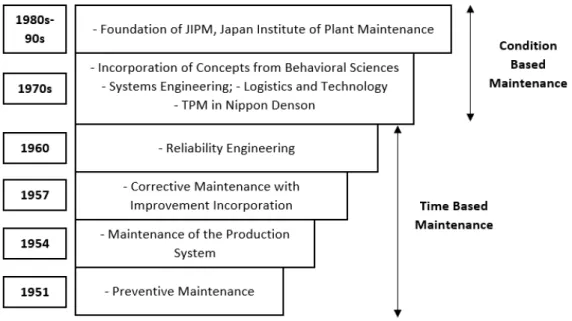
Figure 3.1 shows the temporal evolution of maintenance since it has gained more prominence in the 50s decade.
21
3.2
The Concept of Maintenance
According to the European standard of Maintenance Terminology [24],
mainte-nance is “the combination of all technical, administrative and managerial actions during the life cycle of an item intended to retain it in, or restore it to, a state in which it can
perform the required function”. It is a set of organized activities that are carried out, with the minimum possible cost, in order to keep an item in its best operational condition. Such activities, like repair and replacement, are necessary for an item to reach its ac-ceptable productivity condition [25].
The standard maintenance workflow is represented by a set of sequenced steps to be followed in order to accomplish a maintenance operation, from the first prepara-tory activities, such as study and defining policies, to the analysis once the work is finish and action to be taken to improve future similar cases [26].
Maintenance and production should be interconnected in order to achieve the best success in the industry. For instance, maintenance objectives should be consistent with production goals, like the action of keeping production machines and facilities in the best possible condition [27].
Every equipment, especially in the industry, needs maintenance actions in order to ensure its functionality, operability, and safety. Maintenance activities go beyond those actions, being also directly interconnected with legal and economic reasons.
From an economic point of view the objective of maintenance is to maintain the operability of an equipment for the maximum allowable time, without putting at risk the safety of the facilities where the equipment is being operated as well as the personnel who operates it [28].
22
Figure 3.2 The importance of maintenance in the production process (adapted from [28])
3.3
Types of Maintenance
There are multiple types of maintenance used in the industry, as can be seen in Figure 3.3.
Figure 3.3 Different types of maintenance [27]
23 Planned maintenance is used when the degradation of a given equipment hap-pens in such a progressive way that allows for a planned maintenance action to be set in the most appropriate time.
Unplanned maintenance is used when equipment failure happens in such a
sud-den and unpredictable way that it doesn’t allow for a planned action [29].
Reactive Maintenance
Reactive maintenance is an unplanned type of maintenance where no actions or efforts are taken to maintain the equipment as it was originally planned by the designer in order to ensure that design life was reached.
Studies show that this type of maintenance is still one of the most used due to its low capital cost and low labor needs. However this is often misunderstood, because alt-hough this approach in the short time has lower costs, in reality, during the time that is believed to be savings in maintenance and capital costs, there is being spent more money than it would have under a different maintenance approach. This happens because while waiting for the equipment to break, its life is being shortened, resulting in a more fre-quent replacement. This increased cost would not be experienced had the maintenance program been more proactive. Also, the labor costs associated with the repair will even-tually be higher than normal because the failure will most likely require more extensive repairs than would have been required had the equipment not been run to failure [30].
Corrective Maintenance
Performed after the occurrence of a kind of failure that does not allow the
fur-therance of the equipment’s activity, corrective maintenance is a type of maintenance
planned to restore the equipment’s ability to perform such activities. It can be performed without a delay after the fault has been detected or with a delay according to given maintenance rules [25].
This maintenance type is better suited when [29]:
24
The cost of repair is low;
There is no safety related problems.
Corrective maintenance can be divided in two different categories: deferred and remedial.
Deferred corrective maintenance is performed after the failure occurrence. It
re-quires the cessation of equipment’s activity and is performed to momentarily fix the equipment while waiting for the remedial maintenance activity, which will fix it cor-rectly and permanently.
Remedial corrective maintenance has the objective of treating the cause of failure. It is preceded by a primary cause analysis with the purpose of verifying if there is forced or natural degradation, with a report being created after the registered occurrence.
Preventive Maintenance
Preventive Maintenance (PM) is performed in pre-determined periods or in ac-cordance with approved criteria with the objective of reducing the probability of equip-ment failure [29].
An effective preventive maintenance plan should include planned replacement of components and diagnostic measures. By introducing the element of planning into the maintenance functions, the repair and manpower requirements can be reduced [31]. Preventive maintenance is an important ongoing accident prevention activity which should be integrated in the operations of the manufacturing processes. Some of the advantages of this type of maintenance are:
Improved system reliability; Decreased costs of replacement; Decreased system downtime; Protection of assets;
25
Predictive Maintenance
Predictive maintenance attempts to detect the onset of a degradation mechanism with the goal of correcting that degradation prior to significant deterioration in the com-ponent or equipment. The diagnostic capabilities of predictive maintenance technologies have increased in recent years with advances in sensor technology, and more recently with a new IT concept known as IoT (Internet of Things) [32].
The field of predictive maintenance technology has become increasingly sophis-ticated and technology-driven, making critical the correct training of operators in order to properly use the tools it provides.
The increase in maintenance technology allowed companies to use Condition Monitoring software as a tool to provide more accurate Condition Based Maintenance (CBM), an essential component of predictive maintenance.
Condition Monitoring
Condition Monitoring is a process of continuously monitoring operational char-acteristics of a machine to predict the need for maintenance before a deterioration or breakdown occurs. Condition monitoring has the potential to improve operational effi-ciency by improving the reliability of operation and machine up-time. The monitoring can be done through non-intrusive techniques such as temperature monitoring, oil par-ticulate analysis and ultrasonic analysis; as well as intrusive techniques, usually trans-ducers mounted on the equipment that measure parameters such as vibration, temper-ature and pressure [33], [34].
26
Improvement Maintenance
This type of maintenance is used when the re-establishment of the operating con-ditions can only be done through the modification of the equipment, or when the mainte-nance conditions, in the scope of a maintainability or reliability improvement, recom-mend that such modifications are done [29].
3.4
Availability
Availability is a performance criterion for repairable systems that accounts for both the reliability and maintainability properties of a system. It represents the duration of uptime for operations and is a measure of how often the system is running in satisfac-tory conditions. It is defined as “a percentage measure of the degree to which machinery and equipment is in an operable and committable state at the point in time when it is
needed”[35]. It is often characterized as [36]:
availability =(uptime + downtime)(uptime) (2)
Where:
uptime - Capability to perform the task downtime - No capability to perform the task
In order to have optimal availability, there are three main factors that need to be maximized [36]:
1. Increasing the time to failure;
2. Decreasing the downtime due to repairs or scheduled maintenance; 3. Accomplishing items 1 and 2 in a cost effective manner.
27
Inherent Availability (A
I)
Inherent availability represents the expected level of availability when consider-ing exclusively the downtime for the performance of corrective maintenance. It assumes that spare parts and manpower are 100% available with no delays. It excludes logistics time, administrative downtime, and preventive maintenance downtime. Inherent avail-ability fulfills the need to distinguish expected performance between planned shut-downs and is defined as [35]:
Ai=(MTBF + MTTR)MTBF (3)
Where:
MTBF - Mean Time Between Failures MTTR - Mean Time to Repair
Achieved Availability (A
A)
Achieved availability is similar to inherent availability but counting additionally with preventive maintenance downtimes. It is the steady state availability when consid-ering corrective and preventive downtime of the system. The achieved availability is often addressed as the availability seen by the maintenance department. It includes both corrective and preventive maintenance but does not include logistics time and adminis-trative downtime and is defined below [35]:
AA =(MTBM + MMTBM̅) (4)
Where:
MTBM - Mean Time Between Maintenance actions
28
Operational Availability (A
O)
Operational availability is a measure of the average availability over a period of time and it includes all experienced sources of downtime. It is the probability that an item will operate satisfactorily at a given point in time when used in a realistic environ-ment. It includes logistics time, readiness downtime, administrative downtime, preven-tive maintenance downtime, and correcpreven-tive maintenance downtime. Contrarily to the previous availability terms, operation availability is an a posteriori availability based on actual events that happened to the system. It is the ratio between system uptime and system total time, as given below [35]:
Ao=Operating CycleUptime (5)
Where:
Operating Cycle - overall time period of operation
3.5
Other Approaches
Total Productive Maintenance
Born in Japan, Total Productive Maintenance (TPM) is considered the natural evolution from corrective maintenance to preventive maintenance. It incorporates ef-forts to avoid quality defects caused by wear and malfunction of equipment. The basic foundation is that people that use the respective equipment are more aware and have more knowledge about its problems and should contribute in the repairs and modifica-tions of the equipment [37].
TPM is based in the following elements:
Performance optimization of the equipment;
29 Implementation of continuous improving activities involving all levels of
organization;
Form different teams to reduce defects and self-maintenance; Continuous training of employees;
Costs reduction.
The major difference between TPM and other concepts is that the operators are
also involved in the maintenance process. The concept of “I (Production Operators) op-erate, you (Maintenance Department) fix” is not followed.
The overall objective of TPM is to improve productivity. This can be achieved through the adoption of a life cycle approach for improving the overall performance of production equipment, by motivating workers with a more challenging position with increased job tasks and responsibilities (also called job enlargement), and by using small voluntary group activities to identify the cause of failure and possible plant and equip-ment modifications [38]. In Table 3.1 below, are identified the direct and indirect benefits of using TPM.
Table 3.1 Benefits of using TPM (adapted from [38])
Direct Benefits of TPM Increase the productivity and Overall Plant Efficiency
(OPE) by 1,5 - 2 times;
Rectify customer complaints;
Reduce the manufacturing costs by 30%;
Satisfy the customer needs by 100% (Delivering the right quantity at the right time, in the required quality);
Reduce accidents;
Indirect Benefits of TPM Higher confidence level among the employees;
Favorable change in the attitude of the operators;
Achieve goals by working as a team;
Horizontal deployment of a new concept in all areas of the organization;
30
Reliability Centered Maintenance
Reliability Centered Maintenance (RCM) is the process of determining the most effective maintenance approach, in order to provide the stated function of the facility, with the required reliability and availability at the lowest cost. The concept employs several notions of maintenance, such as preventive maintenance, predictive mainte-nance, real-time monitoring, reactive maintemainte-nance, and proactive maintenance tech-niques in an integrated manner to increase the probability that a machine or component will function in the required manner over its design life cycle with minimum mainte-nance.
The primary RCM principles are [39]:
RCM is function oriented: it seeks to preserve system or equipment func-tion, not just operability;
RCM is system focused: it is more concerned with maintaining the sys-tem function than individual component function;
RCM is reliability centered: it treats failure statistics in an actuarial man-ner. Is seeks to know the conditional probability of failure at specific ages; RCM acknowledges design limitations: maintenance can, at best, only achieve and maintain the level of reliability for equipment which is pro-vided for by design, although maintenance feedback can improve the original design;
RCM is driven by safety and economics: safety must be ensured at any cost; thereafter, cost-effectiveness becomes the criterion;
RCM defines failure as any unsatisfactorycondition: failure can be either a loss of function or a loss of acceptable quality;
RCM tasks must be applicable: the tasks must address the failure mode and consider the failure mode characteristics;
31 The RCM process can be divided in several different steps. The first step is to define the functions of each asset in its operating context, together with the associated desired standards of performance. This can be: primary functions (which summarize why the asset was acquired in the first place) and secondary functions (which recognize that every asset is expected to do more than simply fulfill its primary functions). Done properly, this step alone can take up a third of the time involved in the entire RCM anal-ysis [40].
The second step is to identify the functional failures. RCM process does this at two levels: firstly, by identifying what circumstances amount to a failed state; secondly, by asking what events can cause the asset to get into a failed state. In RCM, failed states are known as functional failures because they occur when an asset is unable to fulfill a function to a standard of performance acceptable to the user.
The third step is to identify all the events which are reasonably likely to cause each failed state. This events are known as failure modes. Most traditional failure modes incorporate failures caused by deterioration or normal wear and tear, but should also incorporate failures caused by human error.
The fourth step in the RCM involves listing the failure effects, which describe what happens when each failure mode occurs. These descriptions should include all the information needed to support the evaluation of the consequences of the failure.
The fifth step is to analyze the failure consequences. RCM recognizes that the consequences of failure are more important than their technical characteristics. In fact, it recognizes that the reason for doing proactive maintenance is to avoid or at least reduce the consequences of failure.
The sixth and last step is to introduce proactive tasks specified for the required failures. RCM divides proactive tasks in three categories: scheduled restoration tasks, scheduled discard tasks and on-condition tasks.
Scheduled restoration tasks entails remanufacturing a component or overhaul-ing an assembly at or before a specified age limit.
32
33
Maintenance
4.1
Historical Evolution of Steam Systems
As soon as mankind was able to boil water to create steam, the necessity of a safety device became evident. As long as 2000 years ago, the Chinese were using caul-drons with hinged lids to allow (relatively) safer production of steam. At the beginning of the 14th century, chemists used conical plugs and later, compressed springs to act as safety devices on pressurized vessels.
Early in the 19th century, boiler explosions on ships and locomotives frequently resulted from faulty safety devices, which led to the development of the first safety relief valve [41].
In 1848, Charles Retchie invented the accumulation chamber, which increased the compression surface within the safety valve allowing it to open rapidly within a nar-row overpressure margin. Today, most steam users are compelled by local health and safety regulations to ensure that their plant and processes incorporate safety devices and precautions, which ensure that dangerous conditions are prevented [42].
34
4.2
Introduction to Steam Systems
Steam is a very efficient, economic and easily controlled heat transfer medium provided from a clean and cheap resource: water. This heat transfer medium is most often used to transport the energy created by the heating source to various locations in the plant and is one of the most widely used media for doing so.
Steam is an essential part of today’s existing industries. Without it a large scope of applications and a wide range of industries could not perform as they do. From the production of energy through steam turbine engines to food processing, steam is present in various sectors and in the production of numerous items. This items include: paper, plastics, building materials, beverages, food, chemicals, textiles, and pharmaceuticals. As well as processes that require the heat supplied by the steam such as: cleaning, heat-ing and the production of energy [44], [45].
Not all steam is the same and different processes require different types of steam. There are three different steam conditions: sub-saturated water or wet steam, saturated steam and superheated steam. This conditions are used in the industry where different processes require different types of steam [46].
The initial pressure that makes the steam transportation possible is created inside the steam boiler by the burner coupled in the combustion chamber or by a heat recovery system integrated in the boiler, usually by using the hot combustion gases to transfer heat into the water. After this initial pressure is generated and all the system is at work conditions, the heat transportation is possible due to the tenuous difference in pressure originated by the heat transfer process. The heat flow occurs due to the temperature differential between the hot steam, created in the boiler, and the steam condensation present in the distribution lines and heat exchangers (condensate has a very small vol-ume compared to the steam, which causes a pressure drop).
35 When steam arrives at the heat exchangers the procedure is completely different. Here the heat transfer is essential, and the purpose is to transfer as much heat as possible from the steam into the process that requires it [47].
A steam system can be split in four different groups: generation, distribution, end use and recovery. This four groups follow the path of steam from its creation to its condensate recovery. Figure 4.1 illustrates this path accordingly.
Figure 4.1 Steam System Scheme [48]
The process starts with the generation of steam in the steam boiler. Here steam is created by transferring heat from the burner combustion gases to the water present in the boiler. After the water is heated enough it shifts into steam. The steam pressure in-creases to a point where it flows to the distribution system [48].
The steam generated in the boiler must be conveyed to the point where its latent heat is required. The steam distribution system makes this possible. It is the connection between the steam generation system and the steam end use.
36
lines, called branch lines, carry the steam from the mains to the end use process. The distribution lines are separated by various types of isolation and pressure-regulating valves. A properly performing distribution system delivers sufficient quantities of high-quality steam at the right pressures and temperatures to the end uses [47], [48].
The system end use is the process requiring the steam produced. The steam will be carried to the process using different equipment depending on the circumstances. End use equipment consists of heat exchangers, turbines, fractionating towers, strippers, and chemical reaction vessels. In some cases the process only requires heat from the steam, not steam itself, for example: when using heat exchangers to supply heat to the cooking process in the food industry. The consumption of the steam produced lowers the overall system efficiency and should be avoided when possible, using only its heat through heat exchangers makes the system much more efficient.
The desirable heat transfer from the steam to the substance heated turns a vast amount of steam into condensate. After this process is complete and the steam has given up its precious latent value, the hot condensate that was created must be promptly re-moved. The recovery system, also known as the condensate system, collects this conden-sate and the condenconden-sate formed during steam transportation and returns it to the feed water tank.
The recovery of condensate has several benefits: it increases the system effi-ciency, lowers the water consumption and reduces the water treatment module chemical consumption, since recovered condensate is already chemically treated and well suited to be introduced into the system.
4.3
Industrial Steam Boilers
37 In case of Bosch Industrial Boilers [49], a capacity of up to 55000 kg per hour of steam is possible to be generated from a single boiler. A boiler of this type, filled with water and ready for operation, can weigh as much as 165 tons. A full capacity boiler of this size converts 3000 liters of fuel oil per hour, which is sufficient to heat more than 2000 houses.
The steam boiler design consists of an horizontal, cylindrical pressure vessel, which is fired through a burner and an internally situated reversing chamber that re-verses the flue gases and leads them back in the second smoke tube pass. On the front of the boiler is an external reversing chamber, which again reverses the flue gases and lead them to the end of the boiler in the third smoke tube pass. Steam boiler vessels are filled with ¾ of water, leaving the upper quarter for the generation of steam [49].
Because of the huge volume of water and the multi-stage lead-through of the flue gases, these boilers are also called three-pass shell boilers. Figure 4.2 shows a sectional drawing of a representative image of a three pass shell boiler.
38
4.4
Steam Distribution Systems
The Steam Distribution System is a bundle of several components that make the steam transportation efficient and safe from the steam generator to the steam end user, supplying steam of the highest reasonable quality. This bundle usually consists of: pipes (also called steam lines), drain points, branch lines, strainers, filters, separators, steam traps, air vents, insulation and the condensate recovery system [46]. Figure 4.3 shows a typical steam distribution system.
Figure 4.3 Steam Distribution System [47]
39 Effective distribution system performance requires proper steam pressure bal-ance, good condensate drainage, complete insulation with regular repair and mainte-nance, and effective pressure regulation. [48]
The Importance of Pressure in the Steam
A kilogram of steam at a higher pressure occupies less volume than at a lower pressure. If steam is generated and also distributed at a high pressure, the size of the distribution mains will be smaller than for a low-pressure system for the same heat load. Generating and distributing steam at a higher pressure has various advantages [48]:
It increases the thermal storage capacity of the system;
It reduces the steam distribution equipment costs due to smaller bore steam mains;
It reduces the steam distribution insulation costs also due to smaller bore mains.
Although distributing steam at a higher pressure being advantageous, the steam pressure still needs to be reduced down to the maximum pressure required at the differ-ent points of use. The local pressure reduction brings another benefit to the steam pro-duced: it makes it drier.
A common and reliable method used for centuries for reducing pressure at the point of use is to use a pressure reducing valve.
4.4.1
Condensate Recovery System
40
the maximum temperature difference existent in start-up conditions, the condensing rate will be at its maximum in these conditions [44].
Once the steam has condensed and given up its valuable latent heat, the hot con-densate must be removed immediately. Concon-densate formed in the distribution steam lines and in the process equipment contains the sensible energy from the steam vapor. It holds as much as 10% of the total steam energy content of a typical system, depending
on the steam pressure and temperature. So it’s still valuable hot water and should be
returned to the boiler feed water. As fuel costs are taken more in consideration, it is one of the highest return on investments and should be imperative to focus on recovering condensate in every industrial steam operation [45], [50].
Condensate recovery is a process of reusing the water and sensible heat con-tained in the discharged condensate. Recovering condensate instead of throwing it away has several benefits [51], [52]:
It increases the system efficiency (depending on the insulation and travel distance);
Lowers the water consumption of the feed water tank;
Reduces the water treatment module chemical consumption (recovered condensate is already chemically treated and well suited to be introduced into the system);
Reduces sewer system disposal costs; Meets environmental regulations;
Reduces energy losses due to boiler blowdown, considering the return of high purity condensate;
Increased fuel savings, as most returned condensate is relatively hot (54 ºC to 107 ºC), reducing the amount of cold makeup water (10 ºC to 16 ºC) that must be heated.
The transport and recovery of condensate for reuse requires a positive pressure differential from the source to the destination, usually a condensate collection area.
41 This is the cheapest method and usually the most reliable, since no special equipment is required.
However, many installations require a pump to transfer condensate to the recov-ery area due to negative differential pressure. In this case, a pumping system is required to transport and recover condensate once the system backpressure becomes higher than the lowest possible trap inlet pressure [53].
Steam traps, installed in proper condensate discharge locations, are the most ef-fective and efficient method of draining condensate from a steam distribution system.
The resulting condensate falls to the bottom of the pipe and is carried along by the steam flow and assisted by gravity due to the gradient in the steam main that should be arranged to fall in the direction of steam flow. The condensate will then have to be drained from various strategic points in the steam main then channeled, collected and temporarily stored in a condensate tank, like the one represented in Figure 4.4 [54].
Figure 4.4 Bosch Condensate Service Module [54]
42
about 50% of the energy content hold by condensate can be lost through flash steam. Therefore, Flash Steam Recovery is an essential part of achieving an energy efficient sys-tem [55].
4.5
Steam System Maintenance
Steam Lines
In order to maintain the efficiency of the steam lines, two major activities are required [56]:
1. Correction of steam leaks; 2. Repair of steam line insulation.
Both represent great losses in efficiency, which leads to a major increase in oper-ation costs. However both problems are recurrently ignored.
In order to detect such problems, routinely surveys should be made. This surveys allow the identification of numerous problems such as:
Steam leaks;
Wet or damage insulation;
Missing insulation.
Steam leaks are very costly to the system operation, however are often ignored due to their repair costs. A steam leak repair usually requires a system shutdown and the replacement or repair of the leaking component. The costs of this operation are often though as too high, but most times the benefits are worth the investment [56].
43 The best way to identify this insulation problems is to survey the entire steam system. Through regular surveys, all leaks and insulation problems must be identified and scheduled for repair, and sources of moisture must be eliminated prior to insulation replacement. In some cases, repairs must be postponed until the system can be shut down for annual maintenance.
Steam Traps
Maintenance of steam traps is often ignored by maintenance workers due to op-erational components being usually enclosed and hidden from view. As a result, atten-tion is only given to this piece of equipment once it starts to give problems, thus making the condensate system faulty [56].
Lack of proper maintenance on steam traps can lead to its failure and cause high losses of steam. Implementation of a comprehensive maintenance program can reduce energy losses due to failed traps, and increase the system efficiency by up to 10% [56].
The correct approach to ensure that steam traps are functioning properly is to implement a regular preventive maintenance program where traps are inspected fre-quently and, if needed, cleaned, repaired or replaced. The program starts with a survey to locate every trap within the steam system and catalogue their size, type, and model. It is wise to develop a mapped route that identifies the location of each trap and recom-mends a route to be followed in order to locate all traps [55].
In addition to the tracking of steam traps, the survey must also test their opera-tion. There are three methods that can be used:
Visual observation; Acoustic monitoring; Temperature measurement.
44
Condensate Return Lines
Condensate return lines are particularly susceptive to corrosion due to the cor-rosive nature of condensate, which results in the need for frequent maintenance. An ap-propriate water treatment system that can separate out aggressive gases from the feed water, and provide a proper water softening, decarboning and desalting, can greatly reduce corrosion in condensate lines [56].
The main purpose of a condensate system maintenance program is to return as much good quality condensate as possible to the boiler. The system’s operation must be continuously monitored. Condensate sample collection and chemical tests should be done daily to track changes in the clean condensate and to take action if needed. Any changes in the sample are indications that the water treatment is not operating properly or that there are leaks in the system [56].
In addition to daily testing, the complete condensate system should be inspected once a year. All sources of air and water leaks must be identified and corrected. Equip-ment connected to the system should be examined for leaks [56].
4.6
Installations Best Practices
Steam Distribution
When working with steam, it is essential that the steam arrives at the farthest heat exchanger. If the boiler is properly sized, the steam will reach it without all of itself turning into condensate. After the initial conditions, the pipes will warm up and highly reduce the amount of condensate generated in the distribution lines.
45 pressure due to friction resistance and condensation within the pipework. Conse-quently, when determining the initial pressure, allowance should be made for this pres-sure loss [44], [47].
Branch line connections shall be taken from the top in order to collect the driest possible steam. If connections were taken from the side, or from the bottom, there would be condensate and debris coming along with steam from the steam mains. The result would be a wet and dirty steam that could affect the performance of the end-use equip-ment. Figure 4.5 shows the proper installation of a branch line connection [47].
Figure 4.5 Correct steam off-take [35]
Drip legs and steam traps shall be installed at all low spots or natural drainage points such as:
Ahead of risers; End of mains;
Ahead of expansion joints or bends; Ahead of valves or regulators.
Drip legs are provided to let condensate escape by gravity from the fast-moving steam, and to store the condensate until the pressure differential can discharge it through the steam trap [58].
46
system where air will gather. Proper installation of air vents require them to be located at high points, at the end of the steam main piping as seen in Figure 4.6, and on all heat exchange equipment [55].
Figure 4.6 Air venting and steam trap at the end of a steam main [55]
Insulation
Important insulation properties include thermal conductivity, strength, abrasion resistance, workability and resistance to water absorption [48].
Removable insulating jackets are available for a wide range of fittings. The use of insulation jackets prevents the fitting surface from radiating heat, thus improving the efficiency of the system. Installation of this jackets should be done according to the fitting
manufacturer’s direction in order to maintain a proper equipment operation [57].
Pipe Sizing
When selecting the size of the piping, consideration should be given to the type of environment in which the steam lines will be located [48].
When determining pipe size, the following factors should be considered:
![Figure 2.2 Types of contradictions (adapted from [4])](https://thumb-eu.123doks.com/thumbv2/123dok_br/16551835.737182/26.892.158.697.276.574/figure-types-contradictions-adapted.webp)
![Figure 2.14 ARIZ flowchart (adapted from [16])](https://thumb-eu.123doks.com/thumbv2/123dok_br/16551835.737182/35.892.205.756.502.882/figure-ariz-flowchart-adapted-from.webp)
![Figure 3.3 Different types of maintenance [27]](https://thumb-eu.123doks.com/thumbv2/123dok_br/16551835.737182/40.892.118.744.499.950/figure-different-types-of-maintenance.webp)
![Figure 4.1 Steam System Scheme [48]](https://thumb-eu.123doks.com/thumbv2/123dok_br/16551835.737182/53.892.163.758.357.742/figure-steam-system-scheme.webp)
![Figure 4.2 Sectional drawing of a three pass boiler [49]](https://thumb-eu.123doks.com/thumbv2/123dok_br/16551835.737182/55.892.174.769.660.956/figure-sectional-drawing-pass-boiler.webp)
![Figure 4.3 Steam Distribution System [47]](https://thumb-eu.123doks.com/thumbv2/123dok_br/16551835.737182/56.892.118.720.391.752/figure-steam-distribution-system.webp)
![Figure 4.4 Bosch Condensate Service Module [54]](https://thumb-eu.123doks.com/thumbv2/123dok_br/16551835.737182/59.892.298.643.576.903/figure-bosch-condensate-service-module.webp)
![Figure 4.5 Correct steam off-take [35]](https://thumb-eu.123doks.com/thumbv2/123dok_br/16551835.737182/63.892.262.645.405.652/figure-correct-steam-off-take.webp)
