a Universidade Regional Integrada do Alto Uruguai e das Missões, Departmento de Engenharia Civil, Erechim, RS, Brasil; b Universidade Federal do Rio Grande do Sul, Programa de Pós-Graduação em Engenharia Civil, Porto Alegre, RS, Brasil.
Received: 07 Feb 2018 • Accepted: 05 Jun 2018 • Available Online: 23 Nov 2018
Simulation of interface behavior between FRP bars
and concrete by an elastic-plastic theory via FEM
Simulação do comportamento da interface entre barras
de FRP e concreto por uma teoria elasto-plástica via MEF
D. S. BRISOTTO a
E. BITTENCOURT b
V. M. R. D. BESSA b
Abstract
Resumo
An elastic-plastic behavior is considered to simulate the interface rupture between grooved, helical wrapped and sand coated helical wrapped bars made of Fiber Reinforced Polymer (FRP) and concrete. Interface properties are obtained comparing results of the model with pull-out experiments. Properties obtained related to grooved bars are similar to properties known for ribbed steel bars. In this case, interface rupture behavior does not depend on bar properties. In case of both helical wrapped bars, on the other side, interface behavior is actually changed by FRP bar characteris-tics. The advantage of the present formulation is its capability to calculate splitting tractions, responsible for bulk concrete failure.
Keywords: concrete, FRP bars, plasticity, finite element.
Um comportamento elasto-plástico é considerado para simular a ruptura da interface entre barras (ranhurada, helicoidal e helicoidal com
areia)de fibra polimérica reforçada (FRP) e o concreto. As propriedades da interface são obtidas comparando os resultados do modelo com ensaios de arrancamento. As propriedades obtidas para a barra ranhurada são similares às propriedades conhecidas das barras de aço ner
-vuradas. Neste caso, o comportamento em ruptura da interface não depende das propriedades da barra. Para as duas superfícies helicoidais, por outro lado, o comportamento da interface é realmente alterado pelas características da barra de FRP. A vantagem desta formulação é a capacidade de calcular trações de fissuração, responsáveis pela ruína do volume de concreto.
1. Introduction
Steel bars have been widely employed in reinforced concrete
structures due to its efficiency and cost-effectiveness. However,
certain environmental conditions can lead to corrosion of these bars and, consequently, the deterioration and even the progressive
collapse of structural elements. In these situations, the use of fiber
reinforced polymer (FRP) as reinforcement in concrete structures has been considered as an alternative in the latter decades due to its high corrosion resistance, high strength-weight relation and cost
efficiency. FRP can be used in different manners as a reinforce -ment: internally as a replacement of the steel bars, externally or
near surface. The present work focuses on the first case.
Just as in the case of steel bars, the bond between FRP bars and concrete is an aspect of fundamental importance on
struc-tural behavior. There are different types of fibers (glass, carbon and aramid) and a wide variety of surface finishes (sand coated,
grooved, ribbed, wrapped, etc.) that may change bond behavior. These characteristics of FRPs are not yet standardized either, so to model bond behavior in such cases is challenging.
Experi-ments sometimes lead to conflicting results as well. For instance,
some researchers [1-3] concluded that FRP bar surfaces have
an effect on the bond strength, while the findings of others [4, 5]
showed the opposite.
In general bond stress is characterized by its relation with bar
slip. In the case of FRP, pre-defined mathematical expressions
have been proposed for these relations, with parameters being obtained by experiments [6-12]. For instance, the American Code ACI440.1R-06 [8] and the Japanese Design Code JSCE [9] pro-vide expressions for bond-slip that are a function of four key fac-tors: concrete strength, bar diameter, concrete cover and bar
loca-tion, but they do not depend on the surface finishing of the bars. On
the other side, Canadian Codes [10, 11] do introduce some surface
effect on bond-slip relations.
However, relations based only on bond stresses are unable to take into account confinement effects that may change bond behavior
drastically. An alternative way to obtain bond-slip relation for FRP
bars including confinement effects would be to consider an elastic-plastic model for the interface. Presumedly the first application of
the elastic-plastic model was made by Guo and Cox [13]. Baky et al. [14] also used this type of model but applied it to concrete struc-tures externally strengthened by FRP plates. Lundgren and Gylltoft [15] used this methodology to study bonding between ribbed steel bars and concrete. In [15] two yield (or failure) surfaces are formu-lated. One surface is related to concrete failure due to shearing and
crushing by bar ribs and occurs when there is enough confinement.
This type of failure is usually called simply pull-out. The other yield surface is related to failure by friction. This kind of failure typically occurs when splitting or longitudinal cracks develop at bulk concrete
due to insufficient confinement and for this reason is called splitting. The distinction between failure modes is important because failure by splitting tends to be much more fragile than failure by pull-out. The present work uses the Lundgren and Gylltoft [15] methodology to explore the rupture of the interface between FRP bars and con-crete and to obtain the evolution of interface properties.
A direct application of ribbed steel bar models to FRP bars is not straightforward, though. The bond failure in both cases is not neces-sarily the same [16-20]. The process can be much more complex in the case of FRP because outer layers of the bars may deform or be damaged during pull-out. For instance, it is now well-known that,
when sufficient confinement is provided, both concrete and FRP ribs
are sheared [17, 21]. If concrete has high strength, damage will de-velop predominantly at the ribs. This kind of failure can be seen in Figure 1, where horizontal dashed lines indicate rupture surfaces, and it will be called here “type I”. For low strength concrete, failure behavior tends to be more similar to pull-out failure observed in steel bars, or concrete is predominantly damaged. This kind of failure will be called here “type II” and it is also depicted in Figure 1. A third and more catastrophic possible failure mode is delamination (type III in Figure 1), but this situation will not be addressed in the present work.
Baena et al. [1] also stressed that surface finishing may change fail
-ure process and its effect is more important for high strength con -crete. Several failure models for the interface FRP-concrete have
been proposed since the end of the last century [19-24]. However
the model proposed in this work is unique in the sense that friction
effects are separated from interface damage.
Only glass fibers and indented bars are taken into account in this work (morphologic definitions follow Baena et al. [1]): grooved fin
-Figure 1
ishing (GF), helical wrapped finishing (HWF) and helical wrapped with sand coated finishing (HWSCF). Using the yield-surfaces de
-fined in Lundgren and Gylltoft [15], the main goal of this work is to obtainnew interface properties for FRPbars, based on the fitting
with experimental results. Also a new rupture model for the
inter-face FRP-concrete is sought, where variables such as confine -mentis also contemplated.All experiments cited and used in this work were taken from the literature.
In section 2 the elastic-plastic model is described; in section 3
sim-ulations are made in order to fit experimental results; a discussion
on how rupture and interfaces properties evolve is made in section
4. Section 5 shows how splitting effects change with FRP finish -ing. Final remarks are presented in section 6. Sub-indexes refer to tensorial components; super-indexes e and p indicate elastic and plastic components, respectively, and super-index T indicates transposed tensor.
2. Elastic–plastic interface formulation
Bond behavior is governed by tractions ti at the interface between concrete and bars. The tangential component (tt) corresponds to bond tractions, while the normal component (tn) corresponds to splitting tractions, with ti= (tn,tt)T.
Total deformation increments (dui) are the sum of elastic deforma-tion increments (duie) and plastic or dissipative deformation
incre-ments (duip) as follows:
(1)
where dui = (dun,dut)T. t
i is a function of elastic deformations and
incrementally calculated as:
(2)
where Dij is the elastic matrix andcan be considered a cohesion
matrix containing the stiffness of linear springs attached to both
sides of the interface.
In order to calculate plastic deformations, elastic limits (yield func-tions) are adopted following Lundgren and Gylltoft [15] as:
F1= |tt|+mtn= 0 (3)
(4)
Originally the authors [15] considered that function F1 represented
failure by friction (splitting failure), where µ is the friction coeffi -cient. F2 represented concrete damage by compression (pull-out failure), for a limit stress c. Details regarding the latter function can be found in ref. [15], but basically it is obtained by equilibrium of compressive forces, which are associated to the resultant of tnandtt tractions, near the interface. By postulate, the same equations for functions F1 and F2 are kept in this work. Representation of eqs. (3) and (4) in tn,tt space is seen in Figure 2.
If F2>0, plastic deformation increments duip are calculated
as follows:
duip= dl∂F2/∂ti (5)
dλ is a plastic multiplier to be determined. Therefore plastic defor-mation is normal to F2 = 0. If F1> 0. a non-associated flow rule is assumed or:
duip= dλ∂G/∂ti (6)
where
(7)
Therefore plastic deformation is normal to G =0. η is taken equal to 0.04 in all cases. This value was obtained for ribbed steel bars [25] and it will be considered the same value in the present work. If both functions are greater than zero, plastic deformation direction goes toward the vertex of F1 =0 and F2 =0 surfaces.
Eqs. (1-7) describe a classic elastic-plastic problem associated to the interface, where dλ is the unknown to be obtained. As
applica-tion to the finite element method is aimed in this work, surface
elements are introduced at the interface concrete-bar. As only axis-symetric applications will be made in this work, the interface sur-face is modeled as a line. The sursur-face elements have four nodes where, initially, two are coincident with the other two creating a zero-thickness (unidimensional) element. Tractions calculated by the procedure above can be then spatially integrated in the
sur-face finite elements, resulting nodal forces. These nodal forces are added to other finite element forces that comes from volumetric
elements. Equilibrium is achieved using a Newton-Raphson itera-tive scheme.
In order to complete formulation, elastic (Dij) and plastic (µ, c)
properties must be defined. Elastic properties follow the definitions
used for ribbed steel bars [25]. So, the equation for the elastic ma-trix Dij is defined as follows:
(8)
where Ec is the elastic modulus for concrete and K11, K12 and K22 are elastic constants of the interface. K22 depends only on
geo-metrical definitions of the bar:
(9)
Figure 2
where A’ is the area of the ribs projected transversely,φ is the bar diameter, lk is the longitudinal distance between the centers of the ribs. K12 depends on the maximal friction of the interface mmax ,
which depends on the bar surface finishing. Its value is obtained
by calibration with experimental results, as discussed in section 4. Although the term mmax is related to the yield surface F2 , tractions tn calculated from this term is still considered an elastic term.
K12= 0.5 K22/mmax (10)
The term D12 in eq. (8) takes into account compressive tractions resulting of the bar pulling process. To avoid an asymmetric elastic matrix, as used in ref. [25], the term D21 is considered equal to D12.
The effect on ttcaused by the introduction of the termD21un is mini-mal because un is several orders of magnitude smaller than ut . As a consequence, numerical results using eq. (8) or an asymmetric version, where D21 = 0, are very similar.
When un is negative K11 is only a penalty factor to avoid inter-pene-tration between FRP and concrete. An arbitrarily high value can be then used. For values of un greater than 0.07mm, a value of 8 m-1
is proposed (this value is an average of previously values used for ribbed steel bars [25], ranging from 5 to 11 m-1). A linear relation is
used for intermediate values of un.
K11 = (0.0105-0.142un) 103/0.07 ; 0 < un < 0.07 mm
K11=8 m-1 ; un ≥ 0.07 mm
(11)
Plastic properties µ and c as functions of the plastic slip are
de-fined in Figure 3, for ribbed steel bars. µ is determined from experi-ments where cylinders of concrete are encased by steel tubes and c is obtained from the post-peak compression stress-strain curve for concrete [15].
One of the main issues of this work is: How these properties are defined and how they evolve with sliding when FRP bars replace ribbed steel bars? Definition of µ function is now taken as the
variation of friction coefficient between concrete and FRP bars. It takes into account the geometry of the bars. Definition of c func-tion is now taken as the post-peak crushing behavior of concrete or both concrete and FRP, depending on failure type. For type II failure the c function is then known and it is equal to the function
seen in Figure 3 (b). But would be very difficult to obtain c func-tions directly from a compression experiment in the case of type I failure. Then comparisons of results obtained from the model with pull-out experiments are used as a guideline to have an insight regarding these properties. In the next section (3), numerical re-sults calibrated to experiments are shown. In section 4, µ andc functions obtained as a result of this calibration process are shown and discussed.
In all cases studied in this work, bars are pulled by monotonic
dis-placements. In the case of steel bars, unloading effects using the
elastic-plastic model described in this work are studied in ref. [25].
Figure 3
m
(a) andc (b) as a function of plastic slip for ribbed steel bars [15,25]
Table 1
Properties of concrete and bars [1]
Bars Concrete
C1 C2
Surface treatment
φ
(mm) fy (MPa)
lk (mm)
A’ (mm2)
K22
(mm-1) mmax
K12 (mm-1)
Es (MPa)
fcc (MPa)
Ec (MPa)
fcc (MPa)
Ec (MPa)
GF 12 1000 9 29.34 0.017 0.32 0.027 60000 29.35 28350 50.5 33000
HWF 8 689 18.39 36.63 0.008 1.2 0.003 46000 – – 46.15 32100
12 689 16.02 46.03 0.0095 1.2 0.004 46000 29.34 28350 47.89 32430
3. Numerical simulations
In this section, the pull-out tests performed by Baena et al. [1] are used to calibrate properties of the proposed model. In all case studied in the present work failures occurred by pull-out, without
delamination. The average bond stress is defined as:
τ= P/πφ lb (12)
where P is the tensile load applied to bar, φ is the bar diameter and lb is the embedded length. In all cases lb=5φ. All concrete speci-mens are cubes with 200 mm sides. Mechanical properties are reproduced in Table 1. Bulk concrete and bars are considered elas-tic-linear, being all non-linearity taken at concrete-bar interfaces. fy and Es are the yield stress and longitudinal elastic modulus for FRP, respectively. fcc and Ec are compression strength and longitu-dinal elastic modulus for concrete, respectively.
For numerical analyzes, the problem is considered axisymmetric with the same cover of the experiments. Only half of the geometry is modeled due to axisymmetry. The bar is modeled by four-node
quadrilateral finite elements and concrete by three-node triangles in a cross-diagonal pattern. In all cases 1960 volumetric finite el -ements are used and are uniformly distributed. Unidimensional interfacial elements are also uniformly distributed throughout lb.
Number of interfacial finite elements depends on bar diameter: 16
elements for φ = 16 mm; 12 elements for φ = 12 mm; and 10 ele-ments for φ = 8 mm. A typical mesh is depicted in Figure 11. The
figure also shows boundary conditions: bar is pulled by prescribed
displacements, with concrete being blocked at the same side bar is pulled. Elastic parameters K22 (see Eq. 9) and K12 (Eq. 10) are also given in Table 1.
Functions µ and c are obtained for φ =12 mm in the case of HWF. Case φ =8 mm was analyzed using the same functions.
The average bond stress-slip relations obtained for GF bars are shown in Figure 4. The pre-peak function is approximately linear and then a relatively fast drop in bond is seen after peak. This kind of behavior is sometimes called slip-weakening [19]. It can be ob-served also that bond strength increases almost linearly with
con-crete strength. As depicted in the figure, a good fitting is observed
between experiments and the numerical model.
The average bond-slip relations obtained numerically and
experi-mentally for HWF bars are presented in Figure 5 for φ = 12 mm, C1
and C2 concrete. A good fitting overall is again visible. In the case
φ = 8 mm, C2 concrete, fitting is not so good for the softening part
of the curve. The reason is that c and µ functions were obtained
specifically for φ = 12 mm. However the model is able to predict
the bond strength increase with diameter decrease reported also experimentally [1, 21].
The ascending branch of the bond-slip function for HWF bars is first linear, but then becomes non-linear before bond peak. For
this reason this type of behavior is denominated slip-hardening. In general, the shape of bond stress-slip relation for these cases
is significantly different from that seen before for GF cases. Under similar conditions, HWF cases present higher bond strength, which
takes place for much larger slips when compared with GF. Finally, Figure 6 presents the average bond stress-slip relations
obtained for HWSCF bars. Overall relations are similar to HWF
cases. Again a good agreement is possible between experiments and simulations although post-peak behavior is somewhat
under-estimated by numerical results. The origin for this difference in
behavior is discussed in the next section, where a model for the interface rupture is described.
As seen, all bond-slip relations present softening. Despite that, convergence to equilibrium was possible by standard Newton-Raphson procedure as only prescribed displacements are applied to the bars.
Figure 4
Numerical and experimental [1] average bond
stress-slip curves for GF bars
Figure 5
Numerical and experimental [1] average
4. Interface rupture
The interface rupture process for each case is described in this section. The procedure employed to estimate the values of the
plastic properties is also described, according to bar finishing.
All bond-slip relations shown have in common an initial linear branch, where minimal damage is expected. Despite the presence of chemical adhesion [22], it is proposed in this work that friction
effects are prevalent in this initial part. All material damage is con -sidered to be associated only to property c. The same formulation
for elastic properties is used (eqs. 8-11) so the relative elastic ef-fect is the same in all cases.
4.1 Grooved finishing
The slope of the linear pre-peak branch observed in experimental bond versus slip relations (Figure 4) is a function of elastic proper-ties and the initial µ value. This dependence can be explained ob-serving Figure 7. Evolution of tt with slipping is shown in Figure 7a for a typical point of the interface (values are negative due to
con-vention arbitrated). Figure 7b shows the coupling effect between tn and tt. From this picture is possible to see that tractions remain on surface F1 at the initial linear branch (0-1), so the slope of the pre-peak depends on µ. As deformations are still small, µ is constant and equal to mmax according to Figure 3a. Relations in Figure 7a remains linear because the friction remains constant. It is possible then to obtain mmax by comparison of this slope with experiments (Figure 4). The result is mmax ≅ 0.32. This value is 68% lower than
mmax for ribbed steel bars (≅ 1, Figure 3a).
At the peak of the bond stress in Figure 4, linear relation ends and
damage by pull-out begins. This point defines the initial c value, as traction combination should reach surface F2 (point 1, Figure 7b). Calculating the radius of this point in tn - tt space (Figure 7b) a value approximately equal to fcc is obtained. Then initial c value for GF is coincident with the corresponding value for ribbed steel bars (Figure 3b). It is interesting to observe that the same peak bond value in Figure 4 could be obtained for a smaller value of c and a greater value of µ, but then numerical results could not be fitted with experiments in the pre-peak region. This conclusion assures that initial values of µ and c proposed are coherent.
As an initial conclusion, it can be said that behavior of GF under pull-out failure is similar to ribbed steel bars or type II failure is prevailing, despite the fact that some damage at the FRP was re-ported by the experimentalists[1]. In fact, the slip-weakening type
Figure 6
Numerical and experimental [1] average
bond-slip curves considering HWSCF bars
Figure 7
(a) Bond traction
versus
slip and (b) the path of tractions in space t
of bond seen for this case is typically associated to steel bars [19].
The differences between the two cases, steel and GF bars, stem only from friction coefficient that is much lower in the latter case.
So, as GF interface properties, the same functions seen in Figure 3 are adopted, except that µ function (Figure 3a) presents a 68% reduction overall.
Once plastic properties are now defined, it is possible to continue
to follow the experiment depicted in Figure 7. A small region where c is constant and µ decreases with plastic slip (1-2) is observed. So the rate of bond decrease immediately after peak is controlled by friction decrease. Behavior of this region is also associated to friction by Katz [19] in some cases. In region 2-3 both c and µ
de-crease, as seen in Figure 3. However the decrease in c function is more substantial, which is in accordance with pull-out failure. After point 3, c and µ are constant and characterize the residual bond strength. The residual value obtained by the model presents good
fitting with experiments, indicating that the proposed plastic func -tions are consistent.
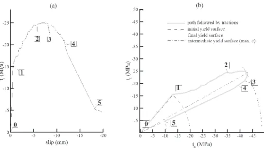
4.2 Helical wrapped cases
Figure 8a shows the evolution of tt with slipping and Figure 8b
shows the coupling between tractions now for HWF. The diameter
considered here for the bar is 12 mm. As in GF cases, the initial slipping (0-1) is controlled by elastic properties and friction as trac-tions remain on F1. From the slope of the linear pre-peak branch observed in experimental bond relations (Figure 5) it is possible to conclude that mmax ≅ 1.2, which is 20% higher than the value for ribbed steel bars. Based on this observation, the same friction function used for ribbed steel bars (Figure 3a) is adopted as an ini-tial proposition, except that it is increased by a 20% factor overall. As in GF bars, the point where linear relation ends provides the initial value of c (point 1, Figure 8). This initial value for HWF cases is much lower than fcc (approximately 50% lower), so obviously the pull-out
process in this case is not only dependent on concrete crushing. Therefore type I failure should be prevailing in this case. A
harden-ing effect in c function is also necessary in region 1-2 because µ
decreases but the bond effect increases (Figure 8a). These obser -vations indicate that a completely newc function must be proposed. A proposition for c function for HWF is shown in Figure 9 and it can be separated in two zones:
a) Pre-peak zone: As already established, pre-peak begins for a value 50% lower than initial value for ribbed steel bars
Figure 8
(a) Bond traction
versus
slip and (b) the path of tractions in space t
n
versus
t
tfor HWF concrete C2
and bar diameter 12 mm, for a typical point of the interface
Figure 9
(Figure 3b, shown again in Figure 9 to facilitate comparisons). This lower value is associated to some damage at the interface
because it is followed by a stiffness decay in bond tractions,
as seen in Figure 8a branch 1-2. Nonetheless a mechanical
interlock is in effect as bond continues to increase with slip. This hardening is generally linked to anchor effects associated
to ribs in shearing process [20]. A peak occurs between points 2-3 in Figure 8a. A value approximately equal to fcc is reached calculating the radius of the peak in tn - tt space (Figure 8b). Therefore maximal value of c should attainsfcc value. (It is inter-esting to note that, as in GF case, the value of tt alone is far off concrete strength andit is possible to conclude that concrete is damaged only because the model considers the coupling be-tween tractions tn and tt). Another characteristic of this function refers to the plastic slip at the peak (up,HW in Figure 9), which is
independent of the fcc in the cases considered. Therefore the increase in concrete strength is not spreading damage at FRP side, otherwise up,HW would decrease when fcc increases. This characteristic of c function must have a limit, but it is valid in the range of materials studied herein.
b) Post-peak zone: This zone is where the pull-out failure takes
place effectively. The slope of this zone is defined by angle αHW
(Figure 9). In the case of type II failure, αHW should be similar
to slope of c for steel bars, aS. This is the case of GF bars
studied in item 4.1. In the present case, as a type I failure is in
play, curve fitting with experiments leads to a steeper c function (higher αHW) or interface deteriorates faster with plastic slip.
Another difference between the curves in Figure 9 relates to the fact that HWF interface continues to deteriorates for larger up
val-ues than GF (up =12 mm). The reason for this behavior is related to
larger lk values in HWF cases (see Table 1).
As a result of µ and c definition, it is possible now to continue to follow the path of tractions in Figure 8. In region 2-3-4, c passes by a maximal value and then decreases, but µ is always decreasing.
Therefore, again in the zone right after peak, a friction effect is in
play. After (4), only c decreases and µ remains constant. Hence,
decay in bond from this point is dominated by shrinking of F2 sur-face, as expected in a failure by pull-out. In (5) residual strength is reached and is consistent with experiments.
4.3 Sand coated cases
HWSCF bars have a similar behavior as discussed for HWF bars.
Using the same reasoning for the two previous cases analyzed, it is possible to conclude that values of µ and c should be slightly
reduced when compared with values used for HWF. One reason
for this reduction can be related to the larger diameter considered
for HWSCF cases (16 mm versus 12 mm). As a result µ function is coincident with that used for ribbed steel bars, Figure 3a, and c
function is similar to HW function depicted in Fig 9, except with a
20% reduction overall.
The model is able to fit experiments until bond strength is reached
for both types of concrete used (C1 and C2), according to Figure
6. However, post-peak behavior indicates that a somewhat smaller
value for αHW would provide a better fitting with experiments. There
-fore the level of damage on HWSC surfaces, in the cases consid
-ered, is slightly smaller than for HW surfaces.
5. Splitting tractions
The methodology permits to investigate the evolution of splitting tractions tn. They can not be calculated by mainstream procedures available for bond estimation [6-12] and normally can not be easily obtained by experiments. Figure 10 depicts the evolution of tn for
GF and HWF with slip (concrete C1, φ =12 mm). It is observed that tnevolves in a similar way to tt in each case, with GF case
peak-ing at the onset of the damage and HWF case presentpeak-ing a peak for larger values of slipping. However, in these cases bonding is much larger for HWF than for GF (see Figs 5 and 4), but Figure 10
indicates that level of splitting tractions is similar. Therefore bond tractions can not be used to estimate splitting tractions.
Besides the interface phenomena studied in this work, traction
com-binations at the interface define also stresses in bulk concrete. In
Figure 11 distribution of hoop stresses (s33) is shown for a 15 mm bar displacement (δ). In the left side results for GF interface are seen
and in the right side results for HWF interface are shown. Only the
right side of the specimen is actually modeled in all cases. Then GF results depicted in Figure 11 was obtained by mirroring the mesh around the symmetry line. Mesh and boundary conditions are also
shown in Figure 11. Sliding of the bars is not the same due to differ
-ent interface stiffnesses in each case. GF bar slipped approximately 14.8 mm and HWF bar 13.9 mm. For this reason HWF bar appears
to be longer than GF bar inFigure 11. For these particular values of slipping, tn is much larger in the HWF case (see Figure 10). As a
consequence, positive hoop stresses are much higher in the HWF
case in this moment of the pull-out test. Positive values also extend much deeper inside bulk concrete in this case. Splitting cracks in reinforced concrete take place once positive hoop stresses around bars are greater than concrete tensile strength beyond certain dis-tant taken from the bar [26]. As a result, the present model is able to detect automatically if splitting failure is occurring (see [25] for more
details). However, in none case analyzed in this work this type of
failure occurred, which is consistent with experimental reports [1].
Figure 10
Splitting traction
versus
slip for GF and HWF,
6. Conclusion
In this work, a model based on previously developed theories, see ref. [15] and [25], was used to simulate the behavior of the inter-face between indented glass FRP bars and concrete. As a result, it was possible to establisha new rupture model for the interface that
takes into consideration the confinement effect.Interface properties
µ and c were also estimated from experiments. It is concluded that:
n For GF bars, c function has the same value as in ribbed steel bars (Figure 3b), indicating that pull-out failure is mainly con-trolled by type II failure (Figure 1). Friction µ, on the other side, is much smaller than corresponding function for steel bars.
n For HWF and HWSCF bars, µ values are comparable to those
for steel bars but c values are quite different (Figure 9), indicat -ing a type I failure (Figure 1).
n The µ function is important to define the initial slope of the bond-slip relation as well as its residual value. It was consid-ered independent of fcc (Figure 3a). µ function variations are
also important to define the slope of the bond-slip relation in
the region immediately after peak.
n Post-peak softening of the bond-slip relation is dominated by c
post-peak. If there is no major damage at the bar surface (type II failure), the slope of c post-peak should be similar to that for steel bars (as, Figure 9). Substantial damage at the bar side
(type I failure), should increase this slope.
n c functions in all cases showed a direct dependence on
con-crete strength fcc(Figure 9) for the experimental cases
ana-lyzed. For HW cases, slip at the peak (up,HW) did not change
with fcc.
The properties described above for c and µ are not intended to be general and are approximately representative of the experiments
done by Baena et al. [1] or similar concrete-bar combinations. More experiments need to be analyzed in order to have an accurate
rep-resentation of these properties. However, this work demonstrates
that FRP-concrete rupture can be represented in details by the
elastic-plastic model described in section 2, considering different
types of bar surfaces.
Loading considered in the applications of this model is monotonic. Be-havior under loading-unloading conditions still needs to be investigated. Besides bond tractions, splitting tractions are also an outcome of the model (Figure 10). This is one considerable advantage of the pro-posed model regarding current methods available to model the FRP-concrete interface. As a consequence, it is possible to have a more complete picture of concrete stresses around the interface and failure of bulk concrete (Figure 11) by using the present methodology.
7. Acknowledgements
The authors gratefully acknowledge the financial support provided
by Brazilian Government through CNPq.
8. References
[1] BAENA M, TORRES L, TURON A, BARRIS C (2009) Experi-mental study of bond behaviour between concrete and FRP bars using a pull-out test. Compos Part B Eng 40(8):784-97.
[2] HAO Q, WANG Y, HE Z, OU J (2009) Bond strength of glass fiber reinforced polymer ribbed rebars in normal strength
concrete. Constr Build Mater 23:865-71.
[3] YAN F, LIN Z, YANG M (2016) Bond mechanism and bond
strength of GFRP bars to concrete: A review. Compos B Eng 98:56-69.
[4] WAMBEKE B, SHIELD C (2006) Development Length of
Glass Fiber-Reinforced Polymer Bars in Concrete. ACI Struct J 103(1):11-7.
[5] MOSLEY CP, TUREYEN AK, FROSCH RJ (2008) Bond
strength of nonmetallic reinforcing bars. ACI Struct Journal 105(5):634-42.
[6] MALVAR LJ (1994) Bond stress-slip characteristics of FRP
rebars. Report TR- 2013-SHR. Naval Facilities Engineering
Service Center.
[7] COSENZA E, MANFREDI G, REALFONZO R (1997) Be -havior and modeling of bond of FRP rebars to concrete. J Compos Constr 1(2):40–51.
[8] ACI Committee 440 ACI 440.1R-06 (2006) Guide for the de-sign and construction of concrete reinforced with FRP bars. American Concrete Institute.
[9] JSCE (1997) Recommendation for design and construction
of concrete structures using continuous fibre reinforcing ma -terials. Research Committee on Continuous Fiber Reinforc-ing Materials, Japan Society of Civil Engineers.
[10] CAN/CSA S806-12 (2012) Design and construction of
build-ing components with fibre-reinforced polymers. Canadian
Standards Association.
[11] CAN/CSA S6-14 (2014) Canadian Highway Bridge Design
Code. Canadian Standards Association.
[12] AMETRANO D (2011) Bond characteristics of glass fibre re -inforced polymer bars embedded in high performance and
Figure 11
Distribution of hoop stresses in concrete and bar
using interfaces for GF (left) and HWF (right).
Stresses are in MPa and all dimensions are in mm.
Boundary conditions used are also shown.
ultra-high performance concrete. Dissertation, Ryerson University.
[13] GUO J, COX JV (2000) An interface model for the mechani-cal interaction between FRP bars and concrete. J Reinf Plast Compos 19:15-33.
[14] BAKY HA, EBEAD U, NEALE K (2012) Nonlinear microme -chanics-based bond–slip model for FRP/concrete interfaces. Eng Struct 39:11-23.
[15] LUNDGREN K, GYLLTOFT K (2000) A model for the
bond between concrete and reinforcement. Mag of Concr Res 52(1):53-63.
16] CHAALLAL O, BENMOKRANE B (1993) Pullout and bond of glass-fibre rods embedded in concrete and cement grout.
Mater Struct 26(3):167-75.
[17] ACHILLIDES Z, PILAKOUTAS K (2004) Bond behavior of fiber reinforced polymer bars under direct pullout conditions.
J Compos Constr 8(2):173-81.
[18] TEPFERS R, LORENZIS LD (2003) Bond of FRP reinforce -ment in concrete – a challenge. J Mech Compos Mater 39(4):477–96.
[19] KATZ, A (1999) Bond mechanism of FRP rebars to concrete.
Mater Struct 32:761-768.
[20] LEE JY, CHONG KY, CHEONG YG, KIM BI (2012) Bond
stress-slip behaviour of two common GFRP rebar types with pullout failure. Mag Concrete Res 64:575-591.
[21] DAVALOS JF, CHEN Y, RAY I (2008) Effect of FRP bar deg -radation on interface bond with high strength concrete. Cem Concr Compos 30(8):722–30.
[22] AIELO MA, LEONE M, PECCE M (2007) Bond performances of FRP rebars-reinforced concrete. J Mater Civ Eng 19:205-13.
[23] COSENZA E, MANFREDI G, REALFONZO R (1997) Be -havior and modeling of bond of FRP rebars to concrete. J Compos Constr 1:40-51.
[24] COX JV, COCHRAN KB (2003) Bond between carbon fiber
reinforced polymer bars na concrete. II: computational mod-elling. J Compos Constr 7:164-71.
[25] BRISOTTO DS, BITTENCOURT E, BESSA VMRA (2012) Simulating bond failure in reinforced concrete by a plasticity model. Comput Struct 106:81-90.