*e-mail: [email protected]
Analysis of the Strength and Stiffness of Timber Beams Reinforced
with Carbon Fiber and Glass Fiber
Juliano Fiorellia, Antonio Alves Diasb*
aSão Carlos School of Engineering - EESC, USP, Brazil
Av. Trabalhador Sãocarlense 400, 13566-590 São Carlos - SP, Brazil
bDept. of Structural Engineering - SET, EESC, USP, Brazil
Av. Trabalhador Sãocarlense 400, 13566-590 São Carlos - SP, Brazil
Received: March 12, 2002; Revised: December 20, 2002
An experimental analysis of pinewood beams (Pinus caribea var hondurensis) reinforced with glass and/or carbon fibers is discussed. The theoretical model employed to calculate the beam’s bending strength takes into account the timber’s ultimate limit states of tensile strength and failure by compression, considering a model of fragile elastic tension and plastic elastic com-pression. The validity of the theoretical model is confirmed by a comparison of the theoretical and experimental results, while the efficiency of the fiber reinforcement is corroborated by the in-creased strength and stiffness of the reinforced timber beams.
Keywords: timber, glass fiber, carbon fiber and reinforced structural
1. Introduction
Problems relating to low efficiency of structural elements increased overload and degradation by aging are common in the construction industry. These pathologies have driven the development of new structural reinforcement and re-covery techniques. The main purpose of recovering an ele-ment is not merely to repair it, but also to prevent and mini-mize the appearance of future problems. Timber structures require repairs in a variety of situations to render them suit-able for renewed use, while in other cases they require rein-forcement to increase the load capacity of their structural elements.
In the last few years, studies have focused on alternative materials for the recovery and reinforcement of structures, and much attention has been dedicated to the use of fibers reinforced with polymer (FRP). This material have high strength, low weight, corrosion resistance and electromag-netic neutrality that make fiber-reinforced plastic (FRP) a suitable candidate in many structural applications, includ-ing rehabilitation and strengtheninclud-ing as well as the develop-ment of new wood members. This material has been stud-ied in the last ten years in United States and Europe with the objective of to reinforce timber structures. More spe-cific glulam beams.
2. Literature Review
Triantafillou & Deskovic (1992)1 establish a technique
to reinforce timber members involving external bonding of FRP sheets on their tension zones. In this work is presented an analytic model that establish a relation between stress and strain for timber. This model considers the timber with an elastic-linear behavior under tensile and an elastic-plas-tic behavior under compression. The fiber is considered as an elastic linear material.
Solid beams of wood were experimentally appraised, reinforced with woven unidirectional of carbon fiber, fas-tened with sticker epoxy, with thickness varying from 0.55 to 0.75 mm. This material was used to reinforce structures to present high strength, high stiffness and low density, com-bining the advantages offered by the materials composites with the efficiency of the external reinforcements, resulting in structural beams with excellent mechanical properties of strength, stiffness and ductility. They got an increase of about 20 to 40% in the capacity of load of the reinforced struc-tural piece.
Belperio & Grad (1999)2 present a theoretical analysis
stiff-ness of the beams the method of the transformed section was used, and for the calculation of the strength, was used a similar analogy used to calculate beams of reinforced con-crete.
For the distribution of stress in the cross section of the reinforced beam, in the failure phase, it was considered that each area acts with the maximum strength. The part of the section above the neutral line was requested by the maxi-mum strength of compression, and below the neutral line, the tensiled section of the timber was considered with lin-eal distribution of stress, acting together with the resulting force of the reinforcement material.
Lindyberg (2000)3 presented a nonlinear probabilistic
model for the analysis of reinforcement Glulam Beams in bending. This work has two principal components. The first part is a deterministic numeric model that calculates the curve of load-deflection of the reinforced beam. This model
is based on the Moment Curvature (M-φ), method
previ-ously used to analyze beams of concrete. The second part incorporates the deterministic model into a probabilistic model. For the development of the deterministic model in-side of the probabilistic it was used the Monte Carlo com-putational simulator.
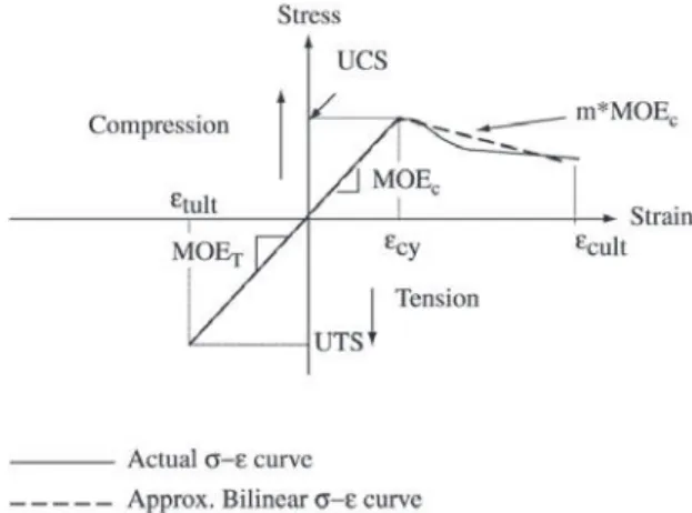
In this work it is assumed a concept that was presented by (Buchanan, 1990)4 where the timber, when submitted to
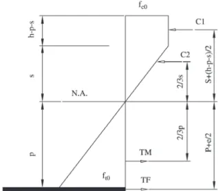
ten-sile efforts, presents an elastic-linear behavior, and when sub-mitted to compression efforts the timber presents an elastic-linear behavior and a nonelastic-linear inelastic behavior (Fig. 1).
Tingley, D. & Kent, S. (2001)5, evaluated box beam
re-inforced with aramid fiber applied along the longitudinal direction of the to grain of the wood. These fibers possessed value of elasticity modulus 59,000 MPa and tensile strength 1034 MPa. As result, observed an increase of 21.5% in the strength and 4.69% in the stiffness, comparing with results obtained for beams without reinforce. The failure type
ob-served in the reinforcement beams was for compression in the superior fibers, after the occurrence of a great plastic strain. Different from the failure of the beams without rein-forces that was for tensile.
Durability of the FRP-wood bond is often a critical fac-tor in the feasibility of a reinforcement technique.
Tingley, D.A. & Cegelka, S. (1996)6 present some
prob-lems that can arise in reinforced wood products. These in-clude shear performance between the reinforcement layers and the wood, dimensional stability of the wood in relation to that of the reinforcement and shear under wet service conditions. Fluctuating moisture content does not affect the dimensional stability of the FRP as it does in wood. This could cause large shear stress to develop at the interface of the FRP and wood over time since wood and wood com-posites can change in dimension by as much as 5 - 7% ver-sus less than 0.01% for FRP. Depending on species and glue line shear capacity, shear failure at the FRP wood interface could occur from this problem alone without applied load. Dagher, H.J. (2000)7 explained that the principal
prob-lems of the reinforced are generally related to incompatibilities between the wood and the reinforcing material. The differences in hygro-expansion and stiffness between the wood and reinforcing materials can lead to sepa-ration at the glue-line, or torsion failure in the wood near the glue-line.
Starting from the analysis of the researches in process, this work presents an experimental analysis of timber beams
of the species Pinus Caribea Var. Hondurensis reinforced
with woven unidirectional of glass fiber and carbon fiber. The experimental results obtained in this research were com-pared with theoretical values. The calculation model con-siders the method of the section transformed for the deter-mination of the stiffness. For the calculation of the moment of failure is used a theoretical model, which considers the plastic elastic behavior of wood, subjected to compression loads and the fragile elastic behavior of reinforcement fibers and of timbers subjected to tensile.
3. Materials And Methods
This topic present the experimental procedure used in this work. The bending tests were made with wood beams of Pinus Caribea Var. Hondurensis species. The cross-sec-tion of the beams, length and the type of reinforcement are presented in Table 1.
After the accomplishment of the bending test in the beams, small size samples were retreated from them, to the accomplishment of parallel compression and parallel ten-sion to grain tests. The mechanical properties of strength and stiffness of the glass fibers and of carbon fibers used in the reinforcement of the timber beams were also determined. Figure 1. Constitutive relationship for wood in tension and
3.1 Characterisation of the Fibers
The properties of tensile strength and elasticity of the glass fibers and carbon fibers were determined by code ASTM D3039/95 – Standard Test Method for Tensile
Prop-erties of Polymer Matrix Composite Materials8, of the
American Society for Testing and Materials.
3.2 Method of Application of the FRP
The lamination process that can be used to fix FRP in wood is the manual. In this process the adhesive is applied on the surface of the fibers. The final product is a laminated material (fibers + adhesive). For the application of the rein-forcement is necessary to clean the timber structure. The Fig. 2 presents the process of application of the fibers.
3.3 Bending Test in Reinforced Timber Beams
The experimental analysis consisted of preparing and testing timber beams of Pinus caribea var. hondurensis spe-cies. The beams were evaluated through bending tests,
ac-cording to the ASTM D198/84 standard, Method of Static Tests of Timbers in Structural Sizes, of the American Soci-ety for Testing Materials9.
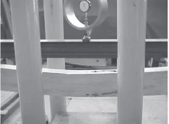
A static design of a simply supported beam was adopted for the tests, with the application of equal loads at one-third intervals of the span (Fig. 3). The values of the displacements were measure in central region of the beam with a dial indi-cator.
The velocity of load application was of 10 MPa per minute, in normal stress maximum.
The volume of FRP relative to volume of timber was 1.0% of glass fiber or 0.4% of carbon fiber, glued with epoxy resin AR-300, onto the internal face of the element, since that is the region subjected to the strongest stresses. Beam number 09 was reinforced with 3.0 % of glass fiber. The re-inforcements of fibers have the same width of the beam.
Number of Dimensions Type of
the beam (cm) reinforcement
01 6 × 12 × 300 Glass Fiber
02 6 × 12 × 300 Glass Fiber
03 6 × 12 × 300 Carbon Fiber
04 6 × 12 × 300 Carbon Fiber
05 6 × 16 × 300 Glass Fiber
06 6 × 16 × 300 Glass Fiber
07 6 × 16 × 300 Carbon Fiber
08 6 × 16 × 300 Carbon Fiber
09 6 × 12 × 300 Glass Fiber
Table 1. Information of the wood beams.
Figure 2. Procedure of application of glass fibers in timber beams.
The beams were instrumented with five extensometer, Kyowa trade mark, type KFG-10-120-C1-11, fixed in cen-tral position (Fig. 4). The objective of this procedure was to evaluate the strain in the cross section of the beam.
3.4 Characterization of the Timber
The timber beams used in the bending tests were char-acterized through the Brazilian code NBR 7190/97 – Projeto de Estruturas de Madeira10. In these analyses the values of
strength and elasticity modulus under compression and un-der tensile parallel to the grain of the timber, using small size simple, were determined.
4. Results
4.1 Test of Characterization of the Fibers
Table 2 presents the mechanical properties of the glass fiber and carbon fiber used in experimental work.
4.2 Bending Test
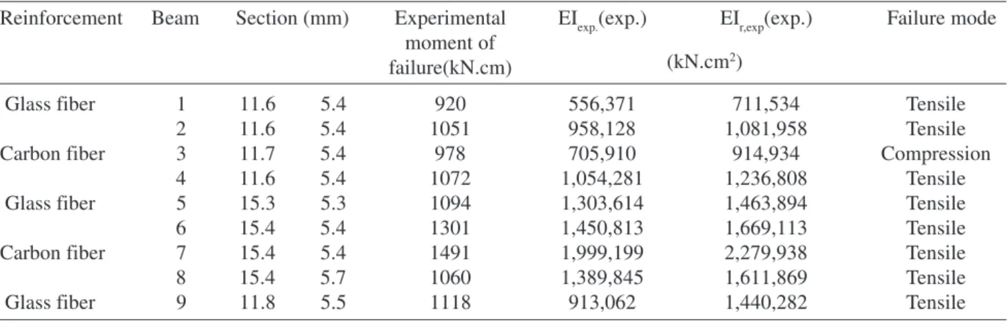
The results of moment of failure, bending stiffness (EI) of the bending test with timber beams reinforced with glass fibers and carbon fibers and the failure mode are present in Table 3.
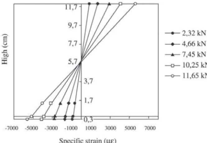
Fig. 5 e 6 presents the strain in a beam 03 of section 6 × 12 cm reinforced with 1.0% of glass fibers. The behavior, of the other beams evaluated, was similar the behavior pre-sented for this beam.
4.3 Test of characterization of the timber
Table 4 present the values of strength and elasticity modulus the compression (fc0 and Ec0) and the tensile (ft0 and Et0) parallel to grain of the wood.
6. Analysis of the Results
6.1 Theoretical Model
The development of a calculation model that determines the value of the ultimate bending strength of fiber-reinforced timber beams is crucial to the material’s correct and safe Figure 4. Position of the extensometer in the cross section of the
beam.
Reinforcement Beam Section (mm) Experimental EIexp.(exp.) EIr,exp(exp.) Failure mode
moment of failure(kN.cm)
Glass fiber 1 11.6 5.4 920 556,371 711,534 Tensile
2 11.6 5.4 1051 958,128 1,081,958 Tensile
Carbon fiber 3 11.7 5.4 978 705,910 914,934 Compression
4 11.6 5.4 1072 1,054,281 1,236,808 Tensile
Glass fiber 5 15.3 5.3 1094 1,303,614 1,463,894 Tensile
6 15.4 5.4 1301 1,450,813 1,669,113 Tensile
Carbon fiber 7 15.4 5.4 1491 1,999,199 2,279,938 Tensile
8 15.4 5.7 1060 1,389,845 1,611,869 Tensile
Glass fiber 9 11.8 5.5 1118 913,062 1,440,282 Tensile
Table 3. Experimental values of moment of failure and bending stiffness.
(kN.cm2)
Tension Modulus of Density
Strength Elasticity (g/cm3)
(MPa) (MPa)
Glass 1100 70,000 2.55
Carbon 2200 180,000 1.75
Unidirectional fiber Characteristics
use in structural reinforcements and repairs, as well as to its broader use in civil construction.
The Brazilian Code NBR 7190/97, Projeto de estruturas de madeira10, is based on the Limit State Method for
verifi-cation of structural safety. In the specific case of fiber-rein-forced beams, the following limit states should be checked: • service limit state in terms of maximum vertical
dis-placement (deflection);
• ultimate limit state in terms of normal stresses caused by the bending moment;
• ultimate limit state in terms of tangential stresses caused by shear stress.
To verify the service limit state, the vertical displa-cements are determined based on bending stiffness and are evaluated according to a linear elastic calculation model (transformed section method).
To determine the ultimate bending moment, the model is similar the developed by Triantafillou & Deskovic (1992)1
and by Lindyberg (2000)3 with simplification of the model
and it was considered elastic plastic behavior to wood sub-jected compression loads and the fragile elastic behavior of reinforcement fibers and of timbers subjected to tension. The evaluation of strength to shear stress will disregard the contribution of the fiber, considering the timber as solely responsible for total absorption of the load.
6.1.1 Evaluation of the Stiffness of Fiber-Reinforced Beams
The stiffness of timber beams reinforced with FRP will be by transformed section analysis.
6.1.2 Analysis of the Failure Moment in FRP Reinforced Beams
This item presents the calculation model for evaluation of the ultimate moment of fiber-reinforced beams. The model is based on the hypothesis of Navier/Bernoulli (plane sec-tions remain plane after being strained) and considers the limit states of the timber’s tension and compression failure.
The theoretical model stabiles that the timber presents an elastic-plastic behavior in parallel compression. The re-lation among the plastic strain (ε2) and elastic strain (ε1) was determined experimentally with compression test it using small size simple of dimensions (3 × 3 × 9 cm) and Figure 5. Moment x specific strain - Pinus beam 03 with section
(6 × 12 cm).
Beam Pinus Caribea var. Hondurensis
Strength (MPa) Elasticity Modulus (MPa)
fc0 ft0 Ec0 Et0
01 36 73 12,410 12,109
02 45 69 15,087 12,771
03 41 62 10,492 8,002
04 48 68 13,044 13,442
05 38 42 11,841 9,426
06 40 56 10,995 8,702
07 42 65 11,921 12,458
08 34 44 10,685 10,835
09 39 59 12,446 14,194
Table 4. Mean strength and modulus of elasticity values.
deflection velocity same the 0.002 mm/min.
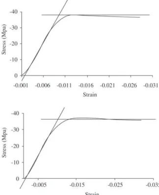
Figure 7 presents one of the tests that were carried out, illustrating the stress versus strain diagram. The relation between the total strain (ε2) and the strain in the elastic phase of the plastic elastic model (ε1) is represented by “k”.
A fragile elastic behavior is considered for the tensioned wood and for the fiber reinforcement, assuming that the tim-ber’s maximum specific strain is equal to that of the fiber. Thus, the relation between the maximum tension acting on the fiber and the maximum tension acting on the timber is equal to the relation between the modulus of elasticity of the fiber and the timber. Because this relation is always much lower than the ratio found for the fiber’s and the timber’s
tensile strength, one can conclude that failure by tension will always occur in the timber.
Figure 8, present the graphics of stress × strain of the compression testing parallel to grain of the wood, used to determined “k”.
The value of “k”, for the species Pinus caribea var. hondurensis, is same the 3. The following considerations were made for the two evaluations (failure by compression or by tension). For ε1 ≤ ε≤ε2, the compression stress of the timber is equal to:
σc = fc0
The strain in the fiber was equal to the maximum strain in the timber, disregarding the strain along the thickness of the fiber. The following denominations were established:
h = beam height; t = fiber thickness;
fc0 = compression strength parallel to the timber’s grain;
m
E
f
s
c c
⋅
=
0; E m
f p
t t
⋅
= 0
;
ft0 = tensile strength parallel to the timber’s grain; Ec = modulus of elasticity to parallel compression on the timber;
(5)
Figure 7. Stress vs. strain in compression parallel to grain.
Et = modulus of elasticity to parallel tension in the timber; Ef = modulus of elasticity to tension of the fiber.
6.1.3 Failure Mode: Compression
The ultimate state of compression is considered to have been attained when the maximum strain in the compressed part reaches the value of ε2. Based on the relations estab-lished between stresses and strains, Fig. 9 shows the distri-bution of stresses when that limit is reached, as well as the forces resulting from those stresses and their positions.
Starting from the condition of equilibrium of the hori-zontal forces and a rearrangement of the terms, one has:
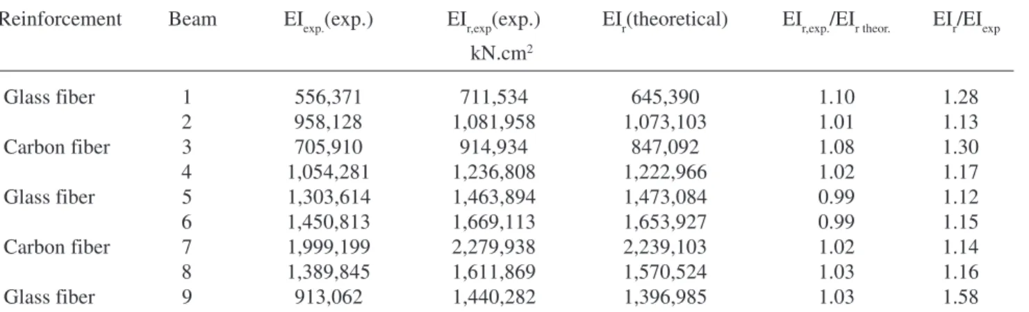
6.2 Comparison Between Experimental and Theoretical Results
The results presented below were obtained both experi-mentally and theoretically, based on the theoretical models presented earlier herein. The Tables 5 and 6 present the ex-perimental and theoretical values of bending stiffness (EI) and moment of failure.
EIexp = experimental value of bending stiffness of the beam no-reinforced;
EIr,exp = experimental value of bending stiffness of the beam reinforced;
EIr = theoretical value of bending stiffness of the beam reinforced.
The values obtained experimentally had a good agree-ment with the theoretical (Table 6). The increase in the
stiff-6.1.4. Failure Mode - Tensile
The timber’s tensile limit state is considered to have been attained when the maximum tensile stress is equal to its tensile strength. Based on the relations established between the stresses and the strains, Fig. 10 illustrates the distribu-tion of stresses when this limit state is attained, as well as the forces resulting from these stresses and their positions. Based on the relations established between the stresses and the strains. Based on the condition of equilibrium of forces, one has:
Figure 9. Distribution of stresses in the transversal section (fail-ure by compression).
Figure 10. Distribution of stresses in the transversal section (fail-ure by traction in the wood).
ness varied from 15 to 30% in beams reinforced with 1.0% of glass fiber and/or with 0.4% of carbon fiber. In the case of beam 09, which was reinforced with 3.0% of glass fiber, the increase in stiffness was significant, i.e., approximately 60%.
The theoretical values of the failure moment were de-termined by failure tensile, more critic situation. Table 6 presents a good relation among experimental and theoreti-cal values. These results indicate the validated of the theo-retical model.
The bending stiffness (EI) and moment of failure deter-mined experimentally were higher than the theoretical val-ues, thus ensuring structural safety. Another important ob-servation is that the use of reinforcement led to an increase of the ductility in the failure phase. The reinforced beams first displayed bearing of the upper fibers by compression, causing an increase in the beams’ strength, followed by ten-sile failure close to the glue line, as presented in Fig. 11.
It was concluded that the proposed calculation model is
Reinforcement Beam EIexp.(exp.) EIr,exp(exp.) EIr(theoretical) EIr,exp./EIr theor. EIr/EIexp
Glass fiber 1 556,371 711,534 645,390 1.10 1.28
2 958,128 1,081,958 1,073,103 1.01 1.13
Carbon fiber 3 705,910 914,934 847,092 1.08 1.30
4 1,054,281 1,236,808 1,222,966 1.02 1.17
Glass fiber 5 1,303,614 1,463,894 1,473,084 0.99 1.12
6 1,450,813 1,669,113 1,653,927 0.99 1.15
Carbon fiber 7 1,999,199 2,279,938 2,239,103 1.02 1.14
8 1,389,845 1,611,869 1,570,524 1.03 1.16
Glass fiber 9 913,062 1,440,282 1,396,985 1.03 1.58
kN.cm2
Table 5. Experimental and theoretical values bending stiffness.
Rein- Beam Experimental Theoretical Relation
forcement moment moment Mexp./
of failure of failure Mtheor.
(kN.cm) (kN.cm)
Glass fiber 1 920 871 1.05
2 1051 938 1.12
Carbon fiber 3 978 934 1.04
4 1072 935 1.14
Glass fiber 5 1094 1085 1.00
6 1301 1400 0.93
Carbon fiber 7 1491 1474 1.01
8 1060 1144 0.93
Glass fiber 9 1118 1056 1.06
Table 6. Experimental and theoretical moment of failure.
valid for the evaluation of fiber-reinforced timber beams. The results of these tests demonstrated the good per-formance of this reinforcement technique, evidenced by the increase in strength and stiffness of the reinforced beams.
The strain, presented in Fig. 5 and 6, indicates that the section plane sections remained plane after being strained. This situation indicates that the hypothesis of the theoreti-cal model is correct. The Fig. 12 presents a comparison among experimental and theoretical values of strains of the beam 03 of section 6 × 12 cm reinforced with 1.0% of glass fibers. To determine the values of the deformation it was used the theoretical model presented on item 6.1. The re-sults indicate that experimental values are close to the theo-retical values (Fig. 12). The behavior of the other beams is similar to the behavior of the beam 03.
7. Conclusions
The theoretical model presented, that is a simplification of other models, led to satisfactory values compared to those obtained experimentally, thus demonstrating their validity. An important factor is observed in the failure mode of the composite: in the first moment occurs the crush of the timber in the compression region of the cross section, above the neutral axis. In the second moment occurs the failure for tensile stress and/or shear stress in the timber.
In this case the timber beams reinforced with fibers pre-sented significant gain in ductility, in comparison with not-reinforced beams. This situation is positive to the structural behavior.
Figure 11. Deflection, followed by tensile failure of the beam.
Figure 12. Moment × strain - Pinus beam 03 section (6 × 12 cm).
Acknowledgements
The authors gratefully acknowledge the support of the Brazilian research financing institution FAPESP – Fundação de Amparo a Pesquisa do Estado de São Paulo.
References
1. Triantafillou, T.; Deskovic, N. Prestressed FRP sheets as external reinforcement of wood members. Journal of Struc-tural Engineering, ASCE, v. 118 (5), p. 1270-1284, 1992.
2. Belperio, R.; Grad, I.E. The Performance of Glulam
Beams Reinforced with Carbon Fibre. In: Pacific
Tim-ber Engineering Conference, New Zeland. Anais. v. 2,
p. 99-106, 1999.
3. Lindenberg, R.F. ReLAM: A nonlinear stochastic model
for the analisys of reinforced glulam beams in bending. Ph.D. Dissertation, Dept. of Civil and Environmental Engineering, University of Maine, Orono, ME, 2000.
4. Buchanan, A.H. Bending Strength of Lumber. Journal Of
Structural Engineering, ASCE. v. 116 (5), p. 391-397, 1990.
5. Tingley, D.; Kent, S. Structural Evaluation of fiber rein-forced hollow wood beams. In. International Associa-tion For Bridge And Structural Engenneering, Malta, Anais. p. 367-372, 2001.
6. Tingley, D.; Cegelka, S. High-Strength-Fiber-Reinforced-Plastic Reinforced Wood. In: Internacional Wood Engi-neering Conference, New Orleans, Lousiana, USA. Anais. v. 3, p. 57-64, 1996.
7. Dagher, H.J. High - Performance Wood Composites for
Construction. In: VII EBRAMEM, São Carlos - Brasil. Anais, 2000.
9. American Society for Testing and Materials. Methods of static tests of timbers in structural sizes. ASTM D198-84. Philadelphia, PA.
10. Associação Brasileira de Normas Técnicas. Projeto de
estruturas de madeira. NBR 7190/97. Rio de Janeiro,