António Maria Ferreira de Lemos Falcão
Optimization of product assignment to assembly
lines
Master Dissertation
Master in Industrial engineering and Management
Work done under the guidance of:
Filipe Pereira Pinto Cunha Alvelos
DIREITOS DE AUTOR E CONDIÇÕES DE UTILIZAÇÃO DO TRABALHO POR TERCEIROS
Este é um trabalho académico que pode ser utilizado por terceiros desde que respeitadas as regras e boas práticas internacionalmente aceites, no que concerne aos direitos de autor e direitos conexos. Assim, o presente trabalho pode ser utilizado nos termos previstos na licença abaixo indicada.
Caso o utilizador necessite de permissão para poder fazer um uso do trabalho em condições não previstas no licenciamento indicado, deverá contactar o autor, através do RepositóriUM da Universidade do Minho.
Licença concedida aos utilizadores deste trabalho
Atribuição CC BY
A
CKNOWLEDGMENTSI would like to express my most sincere gratitude for all those who have accompanied me in this crucial part of my academic life. I want to particularly acknowledge:
Professor Filipe Alvelos, for all the constant support throughout the year. His constant availability, experience, suggestions and guidance were crucial for me to complete this work and without his support this research would not have reached this level.
All of the Bosch team that welcomed me and treated me as part of the group. Thank you for all the experience shared, companionship and coffee breaks talks.
My tutor in Bosch, Luís Florêncio, I must deeply thank for, besides fulfilling amazingly as a tutor, played a very important part in my life as a true friend. I could not have asked for a better person to welcome me in my first professional experience. I will never forget the advises given me and laughs we shared.
Last but certainly not least, I thank my parents, brothers, friends and rest of the family for the constant support on my work and life decisions. You are the foundation of the man I have become today.
DECLARAÇÃO DE INTEGRIDADE
Declaro ter atuado com integridade na elaboração do presente trabalho académico e confirmo que não recorri à prática de plágio nem a qualquer forma de utilização indevida ou falsificação de informações ou resultados em nenhuma das etapas conducente à sua elaboração.
R
ESUMOO trabalho apresentado nesta dissertação foi desenvolvido em contexto industrial integrado no departamento de planeamento e controlo de produção da área de inserção automática da Bosch Car Multimédia Portugal S.A - Braga.
O problema abordado nesta dissertação foi encontrar a melhor distribuição de famílias de produtos a alocar nas diferentes linhas de produção de acordo com as suas restrições físicas e técnicas.
Na abordagem do problema recorreu-se a técnicas de Investigação Operacional através de modelação matemática, para analisar situações complexas e obter soluções mais eficientes. Tendo como base dados da produção, previsões de necessidades e disponibilidade física da produção, foram criados modelos com diferentes conjuntos de restrições e funções objetivo por forma a apresentar soluções que melhor se adequassem à pergunta e ao problema específico do contexto produtivo presente.
Através da utilização de software, foram resolvidos os modelos criados anteriormente, sendo que as soluções foram analisadas e avaliadas para a adequação às necessidades atuais da empresa e para a sua possível e viável implementação.
PALAVRAS-CHAVE
Afetação; Investigação Operacional; Planeamento; Otimização; Gestão Industrial: Inserção automática
A
BSTRACTThe work presented in this dissertation was developed in an industrial context integrated in the production control and management department of the Bosch Car Multimedia Portugal S.A – Braga automatic insertion.
The problem addressed in this dissertation was finding the best distribution of product families to assign in different lines according to the physical and technical constraints of the assembly lines.
In the approach of the problem, it was used tools and techniques of the Operational Research discipline through mathematical modeling, in order to analyze complex situation and obtain more efficient solutions to help in the decision-making process. Based on production data, production needs forecasts and assembly line physical availability, models with different sets of constraints and objective functions were created to present solutions that best fit the question and the specific problem of the present production context.
Through specific software that suited the problem, the previously created models were solved, and the solutions were analyzed and evaluated to suit the company’s current needs and for possible and feasible implementation of the solutions.
K
EYWORDSAssignment; Operation Research; Planning; Optimization; Industrial Management; Automatic Insertion
T
ABLE OF CONTENTS Acknowledgments ... iii Resumo... v Abstract ... vi Figure Index... ix Table Index... xList of abbreviations and acronyms... xi
1. Introduction ... 1 1.1 Background... 1 1.2 Objectives ... 2 1.3 Research Methodology ... 2 1.4 Dissertation Structure ... 2 2. Literature review... 4
2.1 Printed circuit boards assembly system ... 4
2.2 PCB production management ... 5
2.2.1 Setup Strategy Selection ... 5
2.2.2 PCB line assignment ... 6
2.2.3 PCB grouping... 7
2.2.4 PCB scheduling... 8
2.2.5 PCB component allocation ... 8
2.2.6 Feeder assignment and placement sequencing... 9
2.3 Optimization Techniques ... 10
2.3.1 Mathematical programming ... 11
2.3.2 Linear / Integer programming ... 11
2.3.3 Algorithms for Integer Linear Programming... 12
2.3.4 Branch and Bound ... 12
2.3.5 Cutting planes ... 12
2.4 Assignment Problem ... 13
3. Corporate Description ... 16
3.1 BOSCH Group ... 16
3.2 Bosch in Portugal ... 16
3.3 Bosch CM Braga ... 18
3.4 Organizational structure ... 19
4. Problem description and analysis of the current situation... 21
4.1 Production Process ... 21
4.2 Production planning and control department... 22
4.3 Problems identified ... 23
4.4 PCB assignment problem characterization... 24
5. Models ... 26
5.1 Cost minimization model ... 26
5.2 SMD working number minimization ... 27
5.3 SMD workload balance... 28
5.4 Optimization software and data input ... 29
6. Computational experiments... 32
6.1 Results ... 32
6.2 Solution’s Visual Representation ... 35
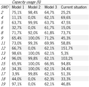
6.3 Capacity adjustment testing... 38
7. Conclusion... 40
References ... 41
Appendix I – New Month Visual solution ... 44
Appendix II – New Month SMD Capacity Usage ... 46
F
IGUREI
NDEXFigure 1: Appropriate methods for each trade-off point. Adapted from (Bhoja, 2002) ... 11
Figure 2: Bosch business sectors, adapted from Bosch CM, internal communication... 16
Figure 3: Bosch Portugal data, adapted from “Bosch CM Corporate Presentation” ... 17
Figure 4: Bosch CM main landmarks, adapted from Bosch CM, internal communication ... 18
Figure 5: Bosch CM product range, adapted from Bosch CM, internal communication ... 18
Figure 6: Bosch client list, adapted from Bosch presentation, internal communication ... 19
Figure 7: Bosch CM Braga organization, adapted from Bosch CM, internal communication... 19
Figure 8: BOSCH CM plant layout, adapted from Bosch CM, internal communication ... 20
Figure 9: MOE1 layout and PCB transportation flux ... 30
Figure 10: Final transportation matrix cost ... 31
Figure 11: Current situation PCB line assignment ... 35
Figure 12: Model 1 PCB line assignment ... 36
Figure 13: Model 2 PCB line assignment ... 37
T
ABLEI
NDEXTable 1: Comparison of the values between models ... 32
Table 2: Computational time comparison ... 33
Table 3: SMD capacity usage ... 33
Table 4: Capacity reduction from freed shifts... 38
L
IST OF ABBREVIATIONS AND ACRONYMSB&B: Branch and Bound
BrgP: Bosch Car Multimedia Portugal CPH: Component per Hour
GA: Genetic Algorithm
GAP: Generalized Assignment Problem GSU: Group Set Up
HP: Hewlett Packard IP: Integer Programming LP: Linear Programming
MOE: Manufacturing Operations Engineering OF: Objective Function
PAP: Pick-and-place PCB: Printed Circuit Board SMD: Surface Mount Devices SMT: Surface Mount Technology
1. I
NTRODUCTION1.1 Background
The electronic industry has already a very competitive environment, where being good and cheap is essential to survive and thrive. As a result, for instance, companies have more attention to the production planning and control areas. Having a better management of all the company’s resources with better and faster decision-making techniques, is a key point for manufactures succeed.
The company in which this dissertation was developed, Bosch Car Multimedia S.A – Braga, is no exception. Being one of the largest national exporters (Madeira, 2017), it dedicates to the development and production of automobile multimedia and sensors. This dissertation was accomplished in a production unit of Bosch CM, the automatic insertion area, where the printed circuit boards (PCB) are produced, which will be later applied in the final product.
In this production unit - MOE1, Manufacturing Operations Engineering, - it is the production planning section –MOE14- who analyzes and decides which product or product family should be produced in a specific assembly line. This planning is made in two levels: a macro level, resultant from the following months prediction of the client demand, and a micro level, obtained from the logistics leveled production. At a micro level, the daily quantities to produce in each assembly lines are defined, in order to achieve the intern client necessities, MOE2, in the correct timeline and quantity.
The problem addressed in this dissertation, can be inserted at a macro level, aiming to help in the medium/long term decision-making. Thus, it is pretended to find the best distribution of the product families to assign in the different assembly lines, respecting the physical and technical line constraints. An extension of the generalized assignment problem will serve as a base model for addressing different variants of the problem of assigning families of products to production lines. In the generalized assignment model, the objective is finding the minimum cost of assigning n tasks to m agents, given that each task is assigned exactly to one agent, subject to the agent’s capacity constraint.(Chu & Beasley, 1997). The difficulty of the problem being addressed is higher, since each product must be assigned twice, one for each side of the PCB.
The approach to address this problem was using operation research methods and tools, through mathematical modelling, in order to analyze complex situations and obtain efficient solutions. The purpose of this is helping in the decision-making process, based on production data, necessity forecast and physical production availability.
1.2 Objectives
This project seeks to analyze and solve an assignment problem between the products and the assembly lines with three different objectives. Firstly, the main objective was to minimize the transportation distance of the PCB, from the first assembly line to the next, in order to get the second side worked. Moreover, other objectives emerged as progress was made, with potential interest. As a second objective, it was pretended to minimize the number of assembly lines being used. Finally, the third objective was to balance all the assembly lines workload.
1.3 Research Methodology
For this dissertation development, the research methodology that best suited was Action Research, which aims to contribute to the goals of a specific science and simultaneously assist with the practical concern of any given problematic situation. (O’Brien, 1998)
According to Susman and Evered (Susman & Evered, 1978) this methodology is organized in five steps, below represented and described:
1. Diagnosing: In this step, the current situation is analyzed, exploring the PCB assembly process and how their assignment to the assembly lines is made. Afterwards, a diagnosis of the problems identified is formulated.
2. Action planning: Once the problems are diagnosed, a few alternative course of actions for solving the problems are defined, including different operation research tools and techniques.
3. Action taking: In this phase, it is necessary to select a course of action from the previous step. In this specific case, three linear integer-programming models are formulated, in order to optimize the PCB assignment to the assembly lines, with three different objective functions.
4. Evaluating: The consequence of the actions taken are evaluated, comparing the new PCB assignments to the current situation, described in step one
5. Specifying learning: Finally, the general conclusions are identified and a final retrospective of the proposed solutions is made according to the respective performance indicators chosen.
1.4 Dissertation Structure
This dissertation is divided in seven chapters as follows.
In chapter 2, the PCB assembly systems and production management are explored, based on the existing literature. Moreover, the assignment problem literature is reviewed, as well as other related
decision-making problems in the electronic industry. Finally, optimization techniques are also addressed, focusing on integer linear programming.
Chapter 3 presents the corporate description, aiming to explore main enterprise landmarks, organizational structure, principal clients and product range.
In Chapter 4 the current factory situation is described and analyzed, identifying the production process steps, as well as problems originated from the current assignment of the PCB. Furthermore, the PCB assignment problem is characterized.
The mathematical models, which solved the problem in question, are addressed in Chapter 5, being characterized and defined.
In Chapter 6, the computational results are presented and analyzed within an industrial engineer context. Moreover, the solutions are visually represented and explored.
Finally, Chapter 7 presents the conclusions of the work presented, as well as suggestions for further improvements and future projects.
2. L
ITERATURE REVIEWIn this chapter, the PCB assembly system is described according to the existing literature. Moreover, an introduction is given to the methods and models for decision-making problems in the production planning of electronic industry. A review of the existing optimization techniques is made, specifically on linear/integer programming models, in addition to the existing methods used to solve these models. Furthermore, existing research works approaching the assignment problem are also introduced, with a following section analyzing the generalized assignment problem (GAP).
2.1 Printed circuit boards assembly system
In today’s digital world, electronic products have a huge impact in our lives and all of them have in common the application of PCB in them. The assembly of PCB is characterized by the insertion of components in the PCB. The most common process in the industry nowadays, is the surface-mount technology (SMT) by surface-mount devices (SMD). (Walwadkar, Kovalchick, Hezeltine, Liang, & McAllister, 2014)
In general, an assembly system consists in five sequential operations connected by conveyors that transport the PCB. The first process consists in the application of a solder paste on the surface of the PCB, where the components are inserted. This process is then inspected in its height, area and position in order to assure the solder paste is correctly applied. Following this, the placement operation begins, in which pick-and-place (PAP) machines insert the components in the PCB. The only mechanism able to move in these machines is the placement head, which must pick up the components from a feeder and afterwards, place them on the desired location of the PCB. This process is called automatic insertion and its duration is, approximately, proportional to the number of components to be inserted and how well optimized are the setup of the machines and the placement order. After all the components have been placed, the PCB goes through an oven, where the solder paste is welded. This is a thoroughly controlled process in which, depending on the PCB and its components, there are different temperature and exposure time profiles. Finally, there is a final inspection that verifies the PCB overall condition, as well as if the components are well placed and in accordance with the defined quality parameters for the different PCB and component types (Prasad, 1997).
Since most of the PCB, due to the final product’s characteristics, need to have both top and bottom side worked to better optimize the component distribution on the PCB, it is necessary to distinguish the two processes as reflow 1 and reflow 2, hence the five processes are repeated twice for each PCB. These
two reflows can be done consecutive or within a limited time space, defined for each PCB (Ho & Ji, 2007). There are additional processes outside of the SMT scope that are dependent of the product, that are explored for Bosch CM Braga production process description, in chapter 4.
2.2 PCB production management
The literature on decision-making problems in the PCB production management is extensive and diverse. To solve all of the existing problems on this area as one is complex so it is necessary to decompose them into smaller problems (Ammons et al., 1993). These smaller problems may include:
• Setup strategy selection
• Assignment of PCB to assembly lines • Grouping of PCB into families • PCB scheduling
• Component types allocation to the assembly machines • Feeder assignment and placement sequencing
All of the above-mentioned problems are reviewed, with an analysis of the past research made on these subjects. They are considered complex problems due to the high amount of possible solutions and the fact that there is no efficient way to determine which one is better.
The problem addressed in this dissertation is the assignment of PCB to the assembly lines, which will be introduced in section 2.2.2, and is the main subject of this dissertation. This problem consists in optimizing the assignment of a PCB or a group PCB to the assembly lines, which have their own capacity limit. The other PCB problems are interesting to study, due to also being decision-making problems in the same industry, having common situations and useful data inputs.
2.2.1 Setup Strategy Selection
In all the PCB manufacturing, there are different setup strategies, differing by the industrial environment and weight given to different objectives, whether it is to minimize changeover times, effort, component placement time per board or even making the best use of the available resources, either it is physical space or feeder slots.
Setup is the physical set of different components, organized in a specific movable table, whereas changeover is the act of changing these tables.
According to Leon & Peters (Leon & Peters, 1998), there are four types of setup strategies that can be identified:
• In the cases where there is a high variety of PCB, but the lot size number is reduced, machine operation optimization does not have the same impact as focusing on minimizing the changeover times between the different PCB on the same SMD. This last is the main objective of the Minimum setup strategy.
• In contrast, in the SMD where there is an allocation of a high-volume of the same PCB type, it is preferred to minimize the component placement time per board. This objective is achieved by optimizing the SMD operations with specific machine algorithms that can, for example, assign components to the SMD feeder slot or schedule the component placement into the PCB. These methods are designated as unique setup strategies.
• Partial setup strategy is characterized, as the name suggests, by partially removing components of the feeder slot, when changing PCB types. The objective of this strategy is also to minimize component placement time, besides changeover time.
• In industrial environments where there is a medium variety of PCB types as well as the batch size number, it is suggested, similar to the minimum setup strategy, to minimize changeover times, being the most impactful objective. It is named as group setup strategy when, instead of the setup taking place between single PCB it is between families of PCB. This grouping should take in account the common components that each PCB has, hence having no major changeover when changing from one PCB type to another from the same family.
2.2.2 PCB line assignment
The PCB line assignment is, as previous mentioned, the problem of optimizing the assignment of different PCB products to the assembly lines, while not exceeding the SMD capacity. The problem has a similar structure to the generalized assignment problem, which will be detailed in section 2.4.1. The objectives of solving the problem can vary, though traditionally, it is mainly concerned in optimizing component placement, machine workload balance, PCB assignment, scheduling or minimizing changeover times.
Ho and Ji (Ho & Ji, 2005) study the PCB line assignment problem and propose a genetic algorithm (GA) approach to solve it. In their literature review, they conclude that there is no research arising in a high volume production environment. The authors propose two mathematical models to optimize the assignment of PCB to assembly lines, while minimizing total production cost. A GA is also proposed and applied in order to solve the problem efficiently. The two mathematical models are solved to optimality
using CPLEX solver and it is demonstrated that the GA can get good quality solutions for the problem much faster, proving to have a better performance.
Balakrishnan and Vanderbeck (Balakrishnan & Vanderbeck, 1993) created an integer linear programming model to assign the PCB to each SMD in order to minimize setup costs, while balancing workload. The environment where the study was done had a high mix and low volume production. The researchers reached a near-optimal solution, by combining an optimization-based method, column generation, heuristics and lower bound procedures.
Hillier and L. Brandeau (Hillier & L. Brandeau, 2001) also study the assignment of PCB to the assembly lines, though their work is more focused on the assignment of the PCB components as it will be reviewed in a next sub section.
2.2.3 PCB grouping
In order to reduce the number of setups from different types of PCB in the production lines it is suggested to group PCB into families with some sort of similarities, so they can be worked as the same way. When using the group setup strategy, all of the PCB in the family are processed in only one setup, hence reducing the changeover time. One of the downsides of this strategy is that the processing time is longer, when comparing to the unique setup strategy. (McGinnis et al., 1992)
Maimon (Freed, Maimon, & DAR-EL, 1989) proposes a group set-up (GSU) method, which he shows, that can significantly reduce changeover times comparing to traditional PCB production methods. The GSU method created in his research suggests dividing the products into groups, which will be produced in two stages. Primarily, the set-up of common components on the machines followed by the assembly of these components on all the PCB in the group is made. Afterwards, there is another set-up of the remaining components and further assembly on each product. In environments where there is a vast number of products sharing common components, and the production volume doesn’t justify buying more than one machine of each type, the GSU method is very advantageous not only reducing changeover time but also reducing throughput time.
Dino and Marco (Luzzatto & Perona, 1993) study the application of Group Technology and Cellular Manufacturing concepts in the scheduling of PCB assembly. The objective of the study is to minimize the number of setups and maximize the workload balance between different machines. The authors develop an heuristic that is tested using a simulated model and later implemented using data from a real PCB assembly system.
Daskin et.al (Daskin, Maimon, Shtub, & Braha, 1997) formulate an integer linear programming problem capable of managing PCB assembly resources. The objective of the research was solving the problem of grouping PCB components in order to minimize the total components and PCB loading costs, subject to the machine’s capacity constraints. Based on these assumptions an heuristic is created to find a solution and finally, different computational results are analyzed.
2.2.4 PCB scheduling
Pinedo (Pinedo, 2008) defines scheduling as the allocation of jobs to machines and their corresponding sequencing, in order to optimize an objective function, being subject to some constraints such as, for example, changeover times. In a typical PCB production system, scheduling is useful, in order to assign products to daily production and the respective release to the assembly lines. Making the best use of all the production resources to improve the overall system performance is the main goal of a scheduling system. The PCB scheduling problem consists in sequencing different lot sized batches such that an objective function is minimized or maximized, considering the job processing, setup time, and the machine cycle time.
Another group of researchers (Lin, Shaw, & Locascio, 1997) study the PCB scheduling problem using a two-level scheduling approach. This approach combines product-level, in order to determine the quantity and type of the products to be daily produced and board-leveling scheduling to optimize the machine capacity allocation, hence improving line productivity. The authors then compare their two-level-scheduling scheme to other existing ones and compare results with real production data.
G.Á. Farkas and P. Martinek (Farkas & Martinek, 2017) introduce a new approach for the scheduling of PCB production. Their objective is to reduce the computational time needed to optimize the model, while simultaneously, minimizing the makespan. To do so, the authors propose three different methods, distinguished by the initialization and the algorithm search tuning. The first method uses an heuristic that pre-processing the input data. The second, uses a valid starting schedule, as an input for the optimization algorithm, reducing significant time on the initialization phase, hence overall computational time. The last method consists on tuning the optimization algorithm, examining the CPLEX Optimization Studio’s Failure Directed Search algorithm.
2.2.5 PCB component allocation
Considering the PCB assignment and grouping as a first management process, the component allocation is the following stage when optimizing PCB production. The electric components should be grouped and allocated to the respective machines, to achieve better cycle times. In the interest of
balancing the workload among different placement machines, the optimization of the allocation of components in the PCB can also be very useful. Since the placement of components usually is the operation that consumes more time among the assembly operation and has the greatest potential on reducing production cost, due to the high cost of the placement machines, there is a special interest by researchers on this subject.
Hillier and Brandeau (Hillier & L. Brandeau, 2001) investigate an operation assignment problem arising from a PCB assembly process. All the process information and data were taken from a Hewlett-Packard (HP) factory, where a vast different number of components need to be inserted in a mix of PCB. The research on how to assign the PCB and components to the machines, so as to minimize total cost while at the same time balancing workloads across machines, is solved using a binary integer formulation. The authors develop an heuristic and an optimal solution method to solve this component assignment problem, which are then used to solve a case study with the use of computational resources to show how effective the results are.
Another group of researchers (Ammons et al., 1993) addresses the problem of allocating components to different machines, in order to balance workload across them, minimizing processing and setup time. The authors develop a mathematical formulation and present two alternative solution approaches to solve the problem. One of the methods is for solving a simple version of the problem with a list-processing-based heuristic, and the second method is based on solving a linear mixed integer program with an adequate solver. Both methods are then used in an industrial case study, in which the results indicate throughput improvements over the company’s current procedure.
2.2.6 Feeder assignment and placement sequencing
Both feeder assignment and placement sequencing can lower total throughput time of the PCB manufacturing, hence reducing production cost. Feeder assignment problems consists in assigning component types to locations on the feeder carriage of the assembly machines, whereas placement sequencing involves specifying the order of the components on the PCB by the assembly machine. The feeder assignment problem is usually modeled as a quadratic assignment problem, whereas the placement sequencing can be modeled as a traveling salesman problem. Both the problems mentioned are known to be NP-hard and should only be solved with efficient heuristics for larger scale problems.
In order to optimize the sequence of component placement on PCB and the arrangement of component types to different machine feeders, Ho and Ji (Ho & Ji, 2004) present a hybrid genetic algorithm. In their study, the objective was to minimize the total travelling distance or time of the
placement head. Comparing the results of other researchers to their algorithm, they can conclude that the performance in reducing travelling distance has superior results.
Other researchers (Crama, Flippo, van de Klundert, & Spieksma, 1997) performed a research on the assembly of PCB where three sub problems arise, the feeder rack assignment problem, followed by the placement sequencing problem and the component retrieval plan problem, all of them studied in a Philips manufacturing plant. Taking as much of the PCB and machine characteristics they heuristically solve the feeder rack assignment problem. Using constructive heuristics and local search methods, the remaining problems are also solved. When tested in one of the Phillips plants, the solution procedure showed notable makespan improvements.
Sun et al. (Sun, Lee, & Kim, 2005) focus their study on the component allocation and feeder arrangement, which they admit are the most important in cycle time optimization. The authors structure the operational decision problems and propose a genetic algorithm capable of solving the before mentioned decisions together. In order to optimize the decisions, the number of simultaneously picked up components for a multi-head module machine is maximized, or the number of pickups is minimized and, at the same time, the workload of the machine gantries is balanced. The authors propose a greedy heuristic for the work cycle formation and pickup sequencing decisions in order to evaluate the workload at each gantry and subsequently, using real industrial data, the algorithms are tested and evaluated.
2.3 Optimization Techniques
In order to optimize PCB assembly systems, there are two well-known approaches to follow. In most cases, getting an optimal solution is only guaranteed, when the problems are formulated as mathematical models and solved using exact algorithms. Another approach is solving the problems using heuristics, which can generate good solutions efficiently.
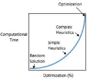
The figure 1, gives an idea of the trade-off between the quality of a solution and the computational effort and the appropriate methods for each trade-off point.
Figure 1: Appropriate methods for each trade-off point. Adapted from (Bhoja, 2002)
As computational time increases, the quality of the solution increases, ideally reaching an optimal solution, whereas in the first instance, the quality of the solution is very poor, being a random solution.
2.3.1 Mathematical programming
There are innumerous programming models used to solve PCB assembly problems. These models are a representation of an industrial context, which after solved, can be used to better understand the actual situation or even help the organization in the decision-making process.
In PCB assembly problems, it is necessary to optimize an objective function. Either it is maximizing or minimizing something like changeover time, component placement time, makespan, just to name a few, subject to constraints such as available capacity.
In this dissertation, an integer-programming model will be formulated for solving the PCB line assignment problem.
2.3.2 Linear / Integer programming
Linear programming (LP) models are characterized by having the objective function and constraints as linear functions. Additionally, the decision variables need to be continuous.
Integer programming (IP) is a specific case of linear programming in which at least one decision variable must take an integer value. Due to some variables being integers instead of continuous, in real life applications, IP is a common modelling method.
In this dissertation developed models, a binary integer programing model is used, in which the variables can only take the value of 0 or 1
Both Linear and Integer programming are well present in the literature and have been studied by several researchers since the 1940s.
The number of applications of LP and IP is huge, many of them in telecommunications networks, production planning and scheduling, logistics, economics, among others. (Fourer, Gay, & Kernighan, 1990)
2.3.3 Algorithms for Integer Linear Programming
Different algorithms can be applied to solve an IP problem. Nowadays, the most successful one, combines branch-and-bound and cutting plane methods, methods which now detailed.
2.3.4 Branch and Bound
The branch and bound (B&B) method was first proposed by Ailsa Land and Alison Doig in 1960 and consists in partitioning the feasible solution region into more manageable subregions and, if required, further partitions of the created subregions. The smaller subregions are constantly evaluated until the best solution is found (Land & Doig, 1960).
First the linear relaxation of the problem is solved using a linear programming algorithm, such as simplex or interior point methods. If the solution obtained by the relaxation is an integer feasible solution, then the method may stop if the optimal solution is found. Otherwise, the B&B algorithm sets up the lower and upper bound for the optimal solution region, tightening the bounds with the branching strategy, until an optimal solution is found, or it is no longer possible to create a new sub problem.
2.3.5 Cutting planes
The cutting-plane method was proposed in the 1950s by Ralph E Gomory as another method for solving integer and mixed-integer programming problems.
The method requires adding constraints that repetitively reduce the feasible region until an integer optimal solution is found. The constraint that is added to the problem is referred as cut, and the IP can then be solved until an integer solution is obtained or if no optimal solution is found the model is considered infeasible. (Gomory, 1960)
In the software used to solve the PCB line assignment problem in this dissertation, the method used was a combination of the branch and bound algorithms and the cutting-planes methods to tighten the linear programming relaxation designated by branch and cut, first introduced by Manfred Padberg and Giovanni Rinaldi, in (Padberg & Rinaldi, 1991).
2.4 Assignment Problem
The assignment problem is widely applied and extensively studied as a combinatorial optimization problem, in which mathematical techniques are applied intended to find optimal solutions within a delimited set of possible solutions, usually defined by a set of restrictions (Veldkamp, 2015). It is formulated similarly as the transportation problem and has innumerous applications in different problems such as data associating problems, load balancing, telecommunications network design and graph bandwidth problems. (Allen, Ismail, Kennington, & Olinick, 2003; Shachnai, Voloshin, & Zaks, 2018)
In the assignment problem there are n agents to execute n tasks. Each agent executes exactly one task, and each task is executed exactly by one agent. The task j being executed by agent i has a cost associated 𝑐𝑖𝑗. The problem is to assign each task to each agent minimizing the cost.(Munkres, 1957)
The model has the following mathematical formulation: Parameters:
𝑖 – Agent, which will perform some sort of task 𝑗 – Task to be assigned
𝑐𝑖𝑗 – cost of assigning agent i to task j
Decision variables: 𝑥𝑖𝑗 = {1, 𝑖𝑓 𝑎𝑔𝑒𝑛𝑡 𝑖 𝑖𝑠 𝑎𝑠𝑠𝑖𝑔𝑛𝑒𝑑 𝑡𝑎𝑠𝑘 𝑗 0, 𝑜𝑡ℎ𝑒𝑟𝑤𝑖𝑠𝑒 Objective Function: 𝑀𝑖𝑛 𝑧 = ∑ 𝑐𝑖𝑗𝑥𝑖𝑗 𝑖𝑗∈𝐴 Subject to: ∑ 𝑥𝑖𝑗= 1, 𝑖 = 1, … , 𝑛 𝑗:𝑖𝑗∈𝐴 ∑ 𝑥𝑖𝑗 = 1, 𝑗 = 1, … , 𝑛 𝑖:𝑖𝑗∈𝐴 𝑥𝑖𝑗 ∈ {0,1}, 𝑖 = 1, … , 𝑛; 𝑗 = 1, … , 𝑛
In order to solve the assignment problem, Harold W. Kuhn (H W Kuhn, 1955; Harold W. Kuhn, 2010), proposed a method, which became known as the Hungarian method, a combinatorial optimization
algorithm, able to solve the problem in polynomial time. The Hungarian algorithm iterates on primal infeasible solutions, reaching feasibility and optimality in the last iteration.
2.4.1 Generalized Assignment Problem
The generalized assignment problem (GAP) differs from the assignment problem because each agent can complete one or more tasks. Moreover, the agent has a capacity limit that cannot be surpassed. In contrast with the assignment problem, the GAP is a NP-hard combinatorial optimization problem. It has been studied considerably by several researchers for more than four decades. Most studies create effective algorithms capable of solving problems of reasonable size to optimality or good quality solutions in reduced time.
The GAP was first studied and solved using the branch and bound method by Ross and Soland in 1975, and it is known for its real-life applications such as vehicle routing, assigning jobs to computer networks, logistics, to name a few. (Cattrysse & Van Wassenhove, 1992)
In the GAP, in which there are n tasks to be processed by m machines, each machine has a given time capacity, and depending on which machine processes which task there is a processing time associated. The GAP is the problem of assigning each task to exactly one machine, in order to minimize the total cost of processing the tasks and each machine does not surpass its available capacity. The problem can be modeled as a linear integer as the following:
Indices:
𝑖 - index of an agent, which will perform some sort of task 𝑗 - index of a task to be assigned
Parameters: 𝑛 - number of agents 𝑚 - number of machines
𝑐𝑖𝑗 – Cost of assigning agent i to task j, i=1,…,n; j=,…,m
𝑤𝑖𝑗 – Capacity usage by assigning agent i the task j =1,…,n; j=,…,m 𝑏𝑖 – Capacity of agent I =1,…,n
Decision variables:
𝑥𝑖𝑗 = {1, 𝑖𝑓 𝑎𝑔𝑒𝑛𝑡 𝑖 𝑖𝑠 𝑎𝑠𝑠𝑖𝑔𝑛𝑒𝑑 𝑡𝑎𝑠𝑘 𝑗
0, 𝑜𝑡ℎ𝑒𝑟𝑤𝑖𝑠𝑒 , 𝑖 = 1 … 𝑛, 𝑗 = 1 … 𝑚 Model
𝑀𝑖𝑛 𝑧 = ∑ ∑ 𝑐𝑖𝑗𝑥𝑖𝑗 𝑚 𝑗=1 𝑛 𝑖=1 Subject to: ∑ 𝑤𝑖𝑗𝑥𝑖𝑗 ≤ 𝑏𝑖, 𝑖 = 1, … , 𝑛 𝑚 𝑗=1 ∑ 𝑥𝑖𝑗 = 1, 𝑗 = 1, … , 𝑚 𝑛 𝑖=1 𝑥𝑖𝑗 ∈ {0,1}, 𝑖 = 1, … , 𝑛; 𝑗 = 1, … , 𝑚
As it is verified in the equations above, the GAP does not have a restriction on the limit of tasks to be assigned to an agent, as long as the capacity usage (𝑤𝑖𝑗) does not exceed the agent capacity (𝑏𝑖).
3. C
ORPORATED
ESCRIPTIONIn this chapter, the company where the project which originated this dissertation, Bosch Car Multimedia Portugal S.A is described, exploring the enterprise history and landmarks, organizational structure, main clients and products.
3.1 BOSCH Group
The BOSCH Group is a well-known global supplier of technology and services, improving quality of life worldwide thriving to shape change. In total, BOSCH Group employs roughly 410 000 associates distributed among more than 60 countries and in 2018 it generated sales of 78.5 billion euros. The four business sectors, in which the company operations are divided, are represented below in the figure 2.
Figure 2: Bosch business sectors, adapted from Bosch Car Multimedia Portugal S.A., internal communication, 2019
Originally, Robert Bosch (1861-1942) set up in Stuttgart the company as a “Workshop for Precision Mechanics and Electrical Engineering” in 1886. Since then the company has changed its legal form into that of a stock corporation, named Robert Bosch GmbH, and is now divided in three shareholders. 92% of the share capital is owned by Robert Bosch Stiftung GmbH, a charitable foundation, 7% held by Bosch family and the remaining 1% are owned by Robert Bosch GmbH. Bosch. (Internal communication, 2019)
3.2 Bosch in Portugal
Bosch was first founded in Portugal, as a sales office in 1911, by Gustavo Cudell in the city of Porto. It was later on, in 1960, that another subsidiary, Robert Bosch Lda., opened in Lisbon, being also responsible for sales and client assistance. Finally, in 1988 Bosch bought Vulcano Termodomésticos in Aveiro, starting its first industrial activity in Portugal. Afterwards, Blaukpunk Auto Radio, that originated Bosch Car Multimedia, opened in 1990 and in 2002 Philips’ Security System in Ovar, was also acquisitioned. (Internal communication, 2018)
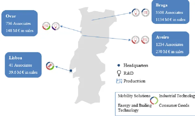
Nowadays, BOSCH has exponentially grown in Portugal and in the figure below it is possible to analyze its numbers.
Figure 3: Bosch Portugal data, adapted from “Bosch Car Multimedia Corporate Presentation, 2018” The main landmarks of Bosch present in Portugal are now enumerated:
• 1911 – Gustavo Cudell establishes 1st Bosch sales office in Portugal • 1960 – Opening of Robert Bosch Lda. in Lisbon
• 1988 – Acquisition of Vulcano Termodomésticos in Aveiro • 1990 – Opening of Blaupunkt Auto-Radio Portugal in Braga
• 2002 – Acquisition of Phillips’ security systems business, including the plant in Ovar • 2009 – Sale of Blaupunkt and reorganization of Bosch Car Multimedia division • 2010 – Opening of ST Communication Center in Lisbon
• 2012 – Bosch signs a contract on an innovation partnership with University of Minho • 2015 – Bosch Braga wins EFQM award
• 2016 – Bosch Braga signs the biggest innovation contract in Portugal with University of Minho • 2018 – Opening of the new Research and Development Center
Figure 4: Bosch CM main landmarks, adapted from Bosch Car Multimedia Portugal S.A., internal communication, 2019
3.3 Bosch CM Braga
The Car Multimedia division provides smart solutions for the integration of entertainment, navigation, telematics, and driver assistance functions in the vehicle, ensuring a fascinating user experience, convenience and comfort. Infotainment systems in vehicles are increasingly incorporating the internet of things and are generally evolving more and more into truly connected systems.
The company portfolio includes globally deployable driver information and infotainment systems, digital instrumentation systems and head-up displays. The Car Multimedia division furthermore supplies communications and entertainment systems for commercial vehicles and coaches. The main products are listed in the image below.
Figure 5: Bosch CM product range, adapted from Bosch Car Multimedia Portugal S.A., internal communication, 2019
Bosch CM Braga is one of Portugal’s biggest exporters, having reached 1.1 billion euros in sales in 2018. Its main costumers include clients from Europe, Asia and South and North America. The
figure below shows the car manufactures that are in the Bosch CM Braga client list.
Figure 6: Bosch client list, adapted from Bosch final company presentation, internal communication, 2018
3.4 Organizational structure
As for the organization structure, Bosch CM Braga is divided in two major areas, technical and commercial, which are managed by two directors who report to Bosch main HQ. There is also a global Logistics department, which operates worldwide amongst Bosch plants. (Bosch Car Multimedia Portugal S.A., internal communication, 2019)
Figure 7: Bosch CM Braga organization, adapted from Bosch Car Multimedia Portugal S.A., internal communication, 2019
N anjing
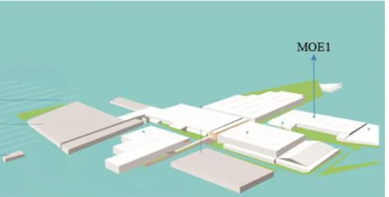
This dissertation project was developed in mini-factory 1 – SMT (MOE1), represented in the figure below, more precisely in the production planning and control department (MOE14), which functions are explored in the next chapter.
Figure 8: BOSCH CM plant layout, adapted from Bosch Car Multimedia Portugal S.A., internal communication, 2019
MOE1 is in this building since 2016, after a big rearrangement of the factory and infrastructure growth, with new buildings. This change brought new challenges since it separated even more the two mini-factory, MOE1 and MOE2, demanding an increasing effort and planning capacity of MOE1, in order to satisfy MOE2 needs.
4. P
ROBLEM DESCRIPTION AND ANALYSIS OF THE CURRENT SITUATIONIn this chapter, a detailed description, as well as a critical analysis of the current state of the company is made. Firstly, the production process is addressed and the MOE14 role in it is described. Then, the existing problems regarding the assignment of PCB in Bosch CM are identified and the reason behind this project existence and importance is exposed. Finally, the PCB assignment problem is characterized considering both the previous review, the existing literature and the specific characteristics of the Bosch Car Multimedia Portugal (BrgP) processes.
4.1 Production Process
The project, which originated this dissertation, was made within the first stage of a large and complex process, situated in MOE1, where the automatic insertion takes place.
In Bosch CM Braga, the production process has some differences between the previously reviewed PCB assembly systems, in subchapter 2.1.
To start, all of the process are fully automatic, being all of the sub processes connected by a conveyor. Initially, a set of PCB are placed in a PCB loader that automatically sends, individually, each PCB to the next sub-process of the assembly. The PCB goes through a laser machine, which prints two identification codes onto the PCB. Following this, the PCB has its surface covered with paste through stencil printing, with a subsequent soldering paste inspection. Afterwards, the PCB undergoes the process of the insertion of the several components, followed by the welding sub-process that occurs in an industrial oven. Finally, the PCB goes through an automatic optical inspection process, where the soldering and welding as well as the correct placement of components is verified. If the desired quality is confirmed, the PCB is unloaded into a specific container, which after fully loaded is temporarily stored in a small buffer. The container then waits for the milk-run carriage to transport it for the next SMD, for the reflow 2 process, where the opposite side is worked. In the reflow 2 process the PCB undergoes the exact same process but with additional care, as the first reflow is now on the bottom of the PCB
There are additional processes outside of the SMT scope that are dependent of the product engineering, design or requirements, such as manual insertion of components and coating application. Furthermore, additional electrical and functional tests may be required for quality purposes. Finally, several products are designed to optimize the automatic insertion and increase the SMD efficiency; to do so, the PCB are designed to have multiple patterns of the final electronic device that can go from 1 to utmost 56 smaller PCB in one PCB. When this occurs, an additional and subsequent process is required
to detach each smaller PCB. This process is called milling where the PCB are detached and an outer frame is removed.
In total, MOE1 has 38 SMD1, though some are better and/or more equipped than others, distinguishing them in three categories, high, medium or low capacity. This category depends on each SMD component placement per hour (CPH), a major key performance indicator (KPI) in the assembly process.
This indicator has a theoretical value, specific of the manufacturer depending of some unique and ideal conditions, such as type, format and complexity of the PCB components. In reality, the CPH of the insertion machines in MOE1 has an inferior value, due to the high variety of different components and PCB. The insertion machines have to take several different pick and place patterns, which lowers the CPH value.
All the production is divided in 8 hours shifts, working 24 hours from Monday to Saturday, with 3 shifts, and 16 hours on Sundays, having 2 shifts. On Sundays, it might be required some additional working hours, depending on the production volume. The production is made possible by 4 teams of operators that rotate between the shifts.
4.2 Production planning and control department
The department in charge of the production planning and control in MOE1 is designated as MOE14. A team of engineers is responsible for assigning the PCB to the SMD, in a short, medium and long term. The developed project aims to improve medium and long term planning, therefore no description of short term planning is presented.
The production planning is triggered by the client order, being received by the logistics department. Resultantly, MOE14 gets from them the final products needed, where they breakdown the final products in the necessary PCB. There are several different PCB types with considerable demand. After knowing the quantity and variety of PCB to be produced, it is necessary for the planners to assign the PCB to the SMD. This is accomplished by first grouping the PCB in families that share common properties and afterwards, the assignment is manually made, based upon the SMD real CPH.
1 At the time of the study, the number of SMD was 38, although this number is constantly changing, due to layout changes. Moreover, the oldest assembly lines can be deactivated when the demand is low
The medium and long term planning, although are not able to predict immediate client deviations or non-planned stops, are an efficient way to prepare the required production resources. That being said, it is correct to say that when the long, medium and short have low deviations between each other, the planning is accurate.
Besides having to do the production planning, MOE14 is also responsible for controlling the daily production. Whether it is stock control, or the more ordinary day-to-day occurrences, MOE14 assures that the production is running smoothly.
Finally, working side by side of the planning department there is also a team of programmers, deciding which programs are needed for the insertion machines software, as well which products are assembled with the same setup. They also manage the extra production such as product samples, another reason why they need to work close to the planners.
4.3 Problems identified
Following the analysis of the current state of the company, it is possible to identify the problems arising from the assignment of the PCB to the assembly lines.
MOE1 occupies an area of 11000 m², within a production building acquired in 2016, which doubled the production area and space between assembly lines, hence between the 38 SMD there is a long distance to travel, being possible to identify a serious problem regarding the intermediate transports between the reflow1 and reflow2 processes. The PCB were travelling big distances to get the second side worked, leading to a big waste of time, as well as accumulated intermediate stock, and consequently its associated costs. Moreover, there was a problem with the milk run carriages traffic, where occasionally, other transportations of raw materials and tools were getting delayed due to waiting times causing production delay. This traffic also had an impact in the overall security with an excess of vehicles going through the same corridors as the rest of the workforce. Furthermore, the containers transporting the PCB can weight up to 8 kg empty and 15 kg fully loaded, causing an impact on the overall workforce health.
An additional problem identified was the time and resources being wasted in manually performing the PCB assignment to the assembly lines by MOE14, which can be significantly reduced by automatizing this process.
In order to optimize transport distance between reflow1 and reflow2 of the PCB, the first mathematical model is formulated, in which the objective is to minimize the intermediate transport distance.
As the project took progress, other problems were identified, such as in times when the production volume demand is lower and not every SMD might be necessarily used. This causes unnecessary use of resources, such as energy, maintenance work, support and workforce. Accordingly, a second mathematical model is formulated, minimizing the number of used SMD. To achieve this objective, a different objective is tackled, by minimizing the number of SMD having PCB assigned, in order to make fully usage of the machines, thus saving costs from SMD that are not necessarily needed.
Moreover, another problem that was identified was the unbalanced machine workload. Some SMD were getting PCB families that were taking processing times much longer than other SMD. This causes a lack of coordination between the several SMD. Accordingly, a third mathematical model is formulated, balancing the total machine workload. This could be accomplished by assigning the necessary PCB, so that the total processing time for each SMD is identical. Balancing the workload would mean that, when there is a drop in the production demand, thus gaining more, capacity for the needed production it is possible to reduce the working hours. This reduction could mean the saving of workforce, maintenance and resource costs.
4.4 PCB assignment problem characterization
In this industrial context, it is considered to have a high variety of PCB types and a low production volume. There are over 5800 distinct PCB types and a demand of a little more than 3 million each month, although these numbers are in constant change. In order to minimize the total number of setups and avoiding that similar PCB are assembled in different SMD, the PCB were grouped into families, depending on the common components, board type and reflow process.
Afterwards, the PCB families are assigned to a SMD ensuring the client demand requirements are met. All PCB families can be processed in any SMD, as long as its capacity is not exceeded. The PCB families take different processing times, depending on the CPH of the automatic insertion machines, number of components each PCB has and the client demand. The demand is given for any specific month of the year and the capacity of the machines is given by the number of hours available to produce in that same month.
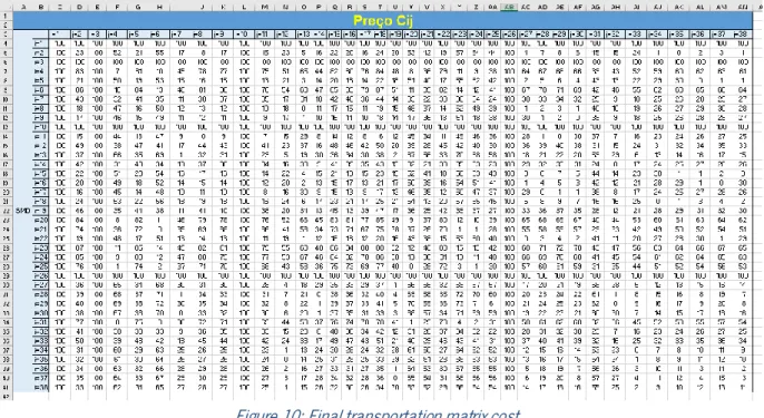
In order to measure the solutions from the developed models, a transportation cost matrix was created, in which there is a proportion of the distance between the different SMD and the total cost of transportation, which is explained better further in this dissertation in subchapter 5.4.
As mentioned, before, the first mathematical model minimizes the total cost between the two processes.
The second model minimizes the number of SMD with jobs assigned, thus maximizing each assembly line usage. Simultaneously, the model also makes the PCB transportation cost between the reflow processes to the minimum.
Finally, the third model balances the processing time between the different SMD while, same has the first and second model, minimizes the transportation cost between the reflow processes.
5. M
ODELSIn this chapter, the three mathematical models for solving the PCB assignment problems previously described are presented. At a first instance, the notation is presented, followed by the models. The three models’ parameters are the following:
𝐾 – Set of PCB families, indexed by: 𝑘 = 1, … , 𝑛 𝐿 – Set of SMD, indexed by 𝑖 = 1, … , 𝑚 or 𝑗 = 1, … , 𝑚 𝑏𝑖 – SMD 𝑖 capacity
𝐶𝑖𝑗 – Cost of the reflow 1 process in SMD 𝑖 and reflow 2 process in SMD 𝑗 𝑝𝑖𝑘1– Processing time of reflow 1 in SMD 𝑖 of the PCB family 𝑘, 𝑖 = 1,… , 𝑚 𝑝𝑖𝑘2 – Processing time of reflow 2 in SMD 𝑗 of the PCB family 𝑘, 𝑖 = 1, … , 𝑚
5.1 Cost minimization model
In this model, the objective is to minimize the cost of product transportation, between the reflow1 and reflow 2 processes. It is assumed the cost is proportional to the distance. The decision variables are:
𝑥𝑘𝑖𝑗={1, if reflow1 of family 𝑘 is produced in SMD 𝑖 and reflow 2 in SMD 𝑗
0, otherwise ,
𝑘 = 1, … , 𝑛; 𝑖 = 1, … , 𝑚; 𝑗 = 1, … , 𝑚
and the model is
𝑀𝑖𝑛 𝑍 = ∑ ∑ ∑(𝑪𝒊𝒋 𝒙𝒌𝒊𝒋 𝑗∈𝐿 ) 𝑖 ∈𝐿 𝑘∈𝐾 Subject to: ∑ ∑ 𝑥𝑘𝑖𝑗 = 1 𝑗 , 𝒊 ꓯ 𝑘 ∈ 𝐾 (1) ∑ ∑(𝑃𝑖𝑘 𝑥𝑖𝑗𝑘+ 𝑃𝑖𝑘 𝑥𝑗𝑖𝑘) ≤ 𝑏𝑖 𝑗 , 𝒌 ꓯ 𝑘 ∈ 𝐾, ꓯ 𝑖 ∈ 𝐿 (2) 𝑥𝑘𝑖𝑗 ∈ {𝟎, 𝟏} ꓯ 𝑘 ∈ 𝐾, ꓯ 𝑖, 𝑗 ∈ 𝐿 (3)
The first constraints (1) force each PCB family (𝑘) to be assigned to one SMD (𝑖) for the reflow 1 process and to one SMD (𝑗) for the reflow 2 process. These constraints force all PCB families to be assembled. In the second constraints (2), the sum of the reflow 1 and reflow 2 processing times of each SMD assigned PCB families, cannot exceed the SMD capacity. Finally, the third constraints (3), define the decision variables domain as binaries.
5.2 SMD working number minimization
The second model has the same parameters as the previous. In this model the objective function minimizes the number of SMD with PCB families assigned. This can be very useful, for times when, the production demand is low and not every SMD might be necessary.
This model has additional decision variables (𝑦𝑖) with respect to the previous one. These variables represent if each SMD is used or not. The decision variables are:
𝑥𝑘𝑖𝑗= {1, if reflow1 of family 𝑘 is produced in SMD 𝑖 and reflow 2 in SMD 𝑗
0, otherwise ,
𝑘 = 1, … , 𝑛; 𝑖 = 1, … , 𝑚; 𝑗 = 1, … , 𝑚
𝑦𝑖 = {1, if SMD i is used (i. e. has at least one job assigned)
0, otherwise , 𝑖 = 1, … , 𝑚 𝑀𝑖𝑛 𝑍 = ∑ 𝑦𝑖 𝑖 ∈𝐿 Subject to: ∑ ∑ 𝑥𝑘𝑖𝑗 = 1 𝑗 𝒊 ꓯ 𝑘 ∈ 𝐾 (1) ∑ ∑(𝑃𝑖𝑘 𝑥𝑖𝑗𝑘+ 𝑃𝑖𝑘 𝑥𝑗𝑖𝑘) ≤ 𝑏𝑖 𝑗 𝒌 ꓯ 𝑘 ∈ 𝐾, ꓯ 𝑖 ∈ 𝐿 (2) 𝑥𝑘𝑖𝑗+ 𝑥𝑘𝑗𝑖 ≤ 𝑦𝑖 , ꓯ 𝑘 ∈ 𝐾, ꓯ 𝑖, 𝑗 ∈ 𝐿: 𝑖 ≠ 𝑗 (4) 𝑥𝑘𝑖𝑖≤ 𝑦𝑖 , ꓯ 𝑘 ∈ 𝐾, ꓯ 𝑖 ∈ 𝐿 (5) ∑ ∑ ∑(𝐶𝑖𝑗 𝑥𝑘𝑖𝑗 𝑗∈𝐿 𝑖 ∈𝐿 ) = 0 ꓯ 𝑘 ∈ 𝐾, ꓯ 𝑖, 𝑗 ∈ 𝐿 𝑘∈𝐾 (6) 𝑥𝑘𝑖𝑗 ∈ {𝟎, 𝟏} , ꓯ 𝑘 ∈ 𝐾, ꓯ 𝑖, 𝑗 ∈ 𝐿 (3) 𝑦𝑖 ∈ {𝟎, 𝟏} , ꓯ 𝑖 ∈ 𝐿 (7)
In this model, the objective function, as the name suggests, minimizes the number of SMD with jobs assigned. The transportation cost between reflows is also minimized to 0, note that there are many solutions with the transportation cost equal to 0, but this model chooses the best solution amongst them, considering the objective function.
The first three constraints (1) (2) (3), are the same as the first model, in which and only one PCB family can be assigned for a reflow 1 and reflow 2 process in a SMD (𝑖) and (𝑗), the sum of the processing times of both reflow processes cannot surpass the available capacity and the decision variable 𝑥𝑘𝑖𝑗 is defined as binary. Same as the third constraints, in (7) it is defined that the decision variable 𝑦𝑖 is binary. Constraints (4), the assignment of a PCB family to complete both reflows in different SMD implies that the SMD are used. Constraints (5) are the same as the previous (4), although the SMD chosen for the assignment must be the same for reflow 1 and 2.
Finally, the last constraints (6) forces the assignment of the PCB family k to do the reflow 1 in SMD i and reflow 2 in SMD j, so as the transport cost is equal to 0.
5.3 SMD workload balance
The third model has the same parameters as the previous ones. In this model the objective is to balance the SMD workload by minimizing the processing time deviation to the mean. This objective is useful for when the production volume justifies the use of all the SMD. In these circumstances, it is necessary to balance the workload, so that when it is needed to reduce the available capacity of working hours, the production is evenly distributed. Assembly lines could finish their tasks almost at the same time, for when the production needs to stop.
This model has two more decision variables ( 𝑠𝑖 and 𝑡𝑖 ), which measure the deviation of the processing times, as it will be later explored.
The decision variables are
𝑥𝑘𝑖𝑗={1, if family 𝑘 does reflow 1 in SMD 𝑖 and reflow 2 in SMD 𝑗
0, otherwise ,
𝑘 = 1, … , 𝑛; 𝑖 = 1, … , 𝑚; 𝑗 = 1, … , 𝑚
𝑠𝑖 – Slack with respect to the average processing time of the SMD i 𝑡𝑖 –Surplus with respect to the average processing time of the SMD i
𝑖 = 1, … , 𝑚 𝑀𝑖𝑛 𝑍 = ∑( 𝑠𝑖 +
𝑖 ∈𝐿
𝑡𝑖 ) Subject to:
∑ ∑ 𝑥𝑘𝑖𝑗 = 1 𝑗 𝒊 ꓯ 𝑘 ∈ 𝐾 (1) ∑ ∑(𝑃𝑖𝑘 𝑥𝑖𝑗𝑘+ 𝑃𝑖𝑘 𝑥𝑗𝑖𝑘) 𝑗 ≤ 𝑏𝑖 , 𝑘 ꓯ 𝑘 ∈ 𝐾, ꓯ 𝑖 ∈ 𝐿 (2) 𝑏𝑖 − ∑ ∑(𝑃𝑖𝑘 𝑥𝑖𝑗𝑘+ 𝑃𝑖𝑘 𝑥𝑗𝑖𝑘) 𝑗 𝒌 + 𝑠𝑖 − 𝑡𝑖 = 𝑏𝑖− ∑ ∑ (𝑃𝒌 𝑗 𝑖𝑘 𝑥𝑖𝑗𝑘+ 𝑃𝑖𝑘 𝑥𝑗𝑖𝑘) 𝐿 , ꓯ 𝑖 ∈ 𝐿 (8) ∑ ∑ ∑(𝐶𝑖𝑗 𝑥𝑘𝑖𝑗 𝑗∈𝐿 𝑖 ∈ 𝐿 ) = 0 𝑘∈𝐾 ꓯ 𝑘 ∈ 𝐾, ꓯ 𝑖, 𝑗 ∈ 𝐿 (6) 𝑥𝑘𝑖𝑗 ∈ {𝟎, 𝟏} ꓯ 𝑘 ∈ 𝐾, ꓯ 𝑖, 𝑗 ∈ 𝐿 (3)
This model’s objective function minimizes the sum of the two deviation variables for all SMD, so that, with the given constraints, the processing time for every SMD is as close as possible to the processing time mean.
The first three constraints (1) (2) (3) are the same as the first two models, in which the decision variable 𝑥𝑘𝑖𝑗 is defined as binary, the sum of the processing times of both reflow processes cannot surpass the available capacity and only one PCB family can be assigned for a reflow 1 and reflow 2 process in a SMD (i) and (j). In the fourth constraints (8), the mean of available processing time across all the SMD must be equal to the available processing time of a specific SMD with the two new variables ( 𝑠𝑖 and 𝑡𝑖 ) adjusting to maintain this equality. The last constraints (6), same as the last model, makes the transport cost of the assignment of the PCB families to be equal to zero.
5.4 Optimization software and data input
In order to solve the developed models, the Gurobi Optimization software and IBM ILOG CPLEX Optimization Studio software were used with AMPL as the modeling language. Moreover, a VBA Microsoft Excel tool was created to analyze the obtained solutions and measure the comparison between the current PCB assignment and the new, obtained from the developed models. To run the application, initially, it is necessary to define the number of SMDs being used. Afterwards, the PCB were grouped into families manually, with the help of an Excel macro, by combining the same board types, similar components, PCB width and the corresponding reflow process. After obtaining the PCB families, each SMD CPH is calculated and the available capacity is given by the working hours of the month in question. Moreover, the processing time of the PCB families in each SMD is calculated, also with the use of an Excel macro. This is possible by dividing the number of components each PCB has by the CPH of each SMD. Finally, the number of SMD available for use is also necessary to be defined.
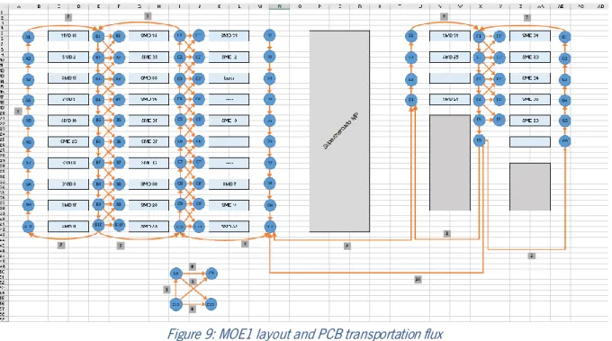
In the figure 10, represented below, it is possible to observe a plant layout of the BrgP MOE1 automatic insertion, in which the rectangles are the different SMD and the blue circles are the position behind and in front of each SMD. This layout was drawn to help create a cost matrix between each SMD reflow. The cost between each position was determined based on the travelling distance of the PCB and are represented by the orange color arrows. There are a few restrictions to be considered in the movement flux, due to the plant layout traffic conditions, also defined by the point of the orange arrows.
Figure 9: MOE1 layout and PCB transportation flux
From the layout representation shown, it is possible to analyze the created cost matrix, in figure 10, which connects all the SMD of the plant layout and gives the associated transportation cost. When finishing the reflow 1 process, if the PCB family is transported to the position in front, the associated cost is equal to 0, and it is considered the best alternative, whereas all of the other combination costs are relative to the distance needed to travel.
Figure 10: Final transportation matrix cost
Once all the user data inputs are completed, it is possible for the desired software solve the models and obtain a solution.
6. C
OMPUTATIONAL EXPERIMENTS6.1 Results
In this chapter, the computational results obtained from the developed models for a specific month are analyzed and compared to the manual assignment (currently in use) of that same period in Bosch CM Braga.
For the specific month analyzed, there are 125 different PCB families and 33 available SMD, with 632 hours of available time. This capacity corresponds to 79 shifts in the time window analyzed with each shift spanning 8 hours.
In order to obtain the solution values of the current situation, the PCB assignment of MOE14 were grouped into families the same way of the developed models. Afterwards, the assignment for both reflows was analyzed and it was verified that, in some cases, the same PCB family was assigned to different SMD in the same reflow process. When comparing to the developed models, this division between SMD is not necessary and only aggravates the transportation flow in the automatic insertion area.
All of the computational tests were run on a laptop Intel Core i5 7200U CPU 2.5 GHz and 8 GB RAM.
In table 1, represented below, the solutions from the developed models are compared to a solution representing the real situation.
Table 1: Comparison of the values between models
Model1 Model2 Model3 Current situation
Transportation cost 0 0 0 2307
SMD used 31 17 31 33
Deviation to the mean (hours)
- - 0 2.5
The developed models were able to obtain an optimal solution for each objective function in reasonable amounts of time as shown below. All three models were able to assign the PCB families with a transportation cost of zero, on contrast to the value of 2307 on the current situation assignment. In model 2, the number of SMD being used is minimized, needing only 17 assembly lines, opposite to the 33 used in the current situation. Moreover, in model 3 there is a deviation to the mean of the processing times of 0, having the SMD workload balanced, whereas the current situation has a value of 2,5.