F
ACULDADE DEE
NGENHARIA DAU
NIVERSIDADE DOP
ORTODevelopment of a Scheduling
Mechanism for Single Radio Stub
Wireless Mesh Networks
Gonçalo Figueiredo Leitão de Sousa Pereira
Mestrado Integrado em Engenharia Eletrotécnica e de Computadores FEUP Supervisor: Prof. Manuel Ricardo
INESC Supervisors: Prof. José Ruela, Eng. Carlos Pinho
Resumo
Uma das tecnologias sem fios mais utilizadas hoje em dia para aceder à Internet é baseada na norma IEEE 802.11. Com a crescente procura de acessos à Internet em contraste com o alcance limitado da tecnologia 802.11, as redes emalhadas 802.11 foram propostas como uma evolução para cobrir áreas mais alargadas e chegar a locais em que a utilização de infraestruturas cabladas não é viável. Juntando o que foi dito à sua flexibilidade e vantagens de natureza económica, as redes emalhadas constituem atualmente uma área de investigação com enorme potencial de aplicação.
No entanto, existem ainda vários objetivos que não foram totalmente concretizados em re-lação à equidade na forma como os recursos são partilhados de forma eficiente em redes emal-hadas, como as regras implementadas para troca de dados ou mesmo a ocupação do meio, que são especialmente importantes para a Qualidade do Serviço oferecida pela rede.
Com base numa solução criada recentemente para redes emalhadas 802.11 denominada WiFIX (Wi-Fi Network Infrastructure eXtension), esta dissertação propõe um mecanismo de escalona-mento que consegue atenuar ou mesmo eliminar problemas conhecidos em implementações de redes emalhadas com vista a melhorar a Qualidade de Serviço nestas redes. Os resultados obtidos com a implementação deste mecanismo de escalonamento e a sua incorporação na versão original do WiFIX demonstram que, por um lado este mecanismo é viável do ponto de vista funcional e tem um grande potencial mas que, por outro lado, existem ainda limitações práticas que impli-cam uma diminuição não desprezável no débito máximo possível, o que justifica a necessidade de investigação adicional para mitigar ou eliminar este problema.
Abstract
One of the wireless technologies mostly used today to access the Internet is based on the IEEE 802.11 standard. With the growing demand of Internet access in contrast with the limited 802.11 range, 802.11-based Wireless Mesh Networks (WMNs) have been proposed as an evolution to cover wider areas and reach places where the use of wired infrastructures is not viable. Besides their flexibility and cost-effectiveness, WMNs constitute today one important area of research with many potential applications.
However, there are still several challenges that have not yet been properly achieved in relation with a fair and efficient share of the available resources in WMNs, like the rules implemented to exchange data or even the occupation of the medium, which are especially important for the Quality of Service offered by the network.
Based on a recently created solution for 802.11-based WMNs named WiFIX (Wi-Fi Network Infrastructure eXtension), this dissertation proposes a scheduling mechanism that can attenuate or eliminate some known problems of WMNs implementations in order to improve the Quality of Service of these networks. The results achieved with the implementation of the scheduling mechanism demonstrate, on one hand, that this method is feasible from a functional point of view and has a great potential but, on the other hand, there are still some practical limitations that imply a non-negligible degradation of the maximum achievable throughput, which justifies further investigation in order to mitigate or eliminate this problem.
Agradecimentos
Gostaria de agradecer aos meus orientadores: Professor José Ruela e Engenheiro Carlos Pinho pela importante coordenação neste projeto e ajuda no desenvolvimento deste documento; e Professor Manuel Ricardo pela disponibilidade e acessibilidade que ofereceu. Queria agradecer também ao Engenheiro Filipe Ribeiro por toda a ajuda e suporte no desenvolvimento da parte mais técnica do trabalho. Um agradecimento ao Professor Rui Campos pela sua contribuição na discussão e resolução de problemas neste projeto.
Agradeço aos meus pais pela minha educação e pela pessoa que sou hoje.
Por fim, agradecer à minha namorada Rita Mendes e aos meus amigos que nunca deixam de acred-itar em mim e todos os dias me inspiram.
Gonçalo Pereira
Contents
1 Introduction 1 1.1 Context . . . 1 1.2 Problems . . . 2 1.3 Motivation . . . 2 1.4 Objectives . . . 31.5 Structure of the Dissertation . . . 3
2 State of the Art 5 2.1 Single-Hop Wireless Connections with CSMA/CA . . . 5
2.1.1 Hidden Node Problem . . . 6
2.1.2 RTS/CTS Exchange . . . 6
2.1.3 Exposed Node Problem . . . 7
2.2 Solutions for Single-Hop Problems . . . 8
2.3 Multi-hop Wireless Networks . . . 9
2.3.1 Wireless Mesh Networks . . . 9
2.3.2 Fairness Problem . . . 10
2.4 Solutions for Fairness Problem . . . 13
2.5 Spatial Reuse . . . 14
2.6 WiFIX . . . 15
2.6.1 Active Tree Topology Creation and Maintenance . . . 15
2.6.2 Eo11 Encapsulation . . . 16
2.6.3 IEEE 802.1D bridges . . . 17
2.6.4 Implementation in LINUX . . . 18
2.7 Smart Grids as an application example . . . 19
3 Specification of PACE Mechanism 21 3.1 Operation . . . 21
3.2 Queues . . . 22
3.3 Polling Control Packet . . . 22
3.4 PACE and the WMNs Problems . . . 24
4 Work Developed 25 4.1 Modifications to WiFIX to support PACE . . . 25
4.1.1 New MAP Message . . . 25
4.1.2 New Terminal Message . . . 26
4.2 Implementation of PACE . . . 27
4.2.1 List of MAPs in Master MAP . . . 27
4.2.2 Packet Queues . . . 27
viii CONTENTS
4.2.3 Polling Control Packet (PCP) . . . 29
4.2.4 PACE Mechanism . . . 29
5 Results and Discussion 33 5.1 Equipment and Configurations . . . 33
5.2 PACE Mechanism Experiments and Evaluation . . . 34
5.2.1 First stage: MAPs waiting for their opportunity to communicate . . . 35
5.2.2 Second stage: packet queues working . . . 38
5.2.3 Comparison with ns-3 simulation results . . . 39
5.3 Problem of Throughput Reduction . . . 40
5.3.1 Experiments . . . 40
5.3.2 Discussion . . . 42
6 Conclusions and Future Work 45 6.1 Objectives Satisfied . . . 45
6.2 Contributions . . . 45
6.2.1 Implementation of PACE Mechanism . . . 45
6.2.2 Study of Throughput Degradation with PACE Mechanism . . . 46
6.3 Future Work . . . 46
A Equipment Specifications 47 A.1 Alix 3D3 . . . 47
A.2 MikroTik RouterBOARD R52n-M miniPCI network adapter . . . 47
B Packages for OpenWRT 49 B.1 Fundamental packages for each system . . . 49
B.2 Extra packages . . . 49
C Throughput results 51 C.1 First Stage . . . 51
C.2 Second Stage . . . 52
List of Figures
2.1 Hidden Node Problem . . . 6
2.2 RTS/CTS validation mechanism [4] . . . 7
2.3 Exposed Node Problem . . . 7
2.4 Example of a pure contention based sender-initiated protocol with RTS/CTS ex-change [5] . . . 8
2.5 Busy tone signal-based protocol [5] . . . 9
2.6 Multiple channel-based protocol [5] . . . 9
2.7 Example of a Stub Wireless Mesh Network [7] . . . 11
2.8 An example of transmission scenario with information asymmetry [8] . . . 11
2.9 Traffic Agregation [8] . . . 12
2.10 Example of Spatial Reuse . . . 16
2.11 WiFIX: Establishing Virtual Links [1] . . . 16
2.12 WiFIX: Topology Refresh Message [1] . . . 17
2.13 WiFIX: Eo11 Encapsulation [1] . . . 17
2.14 WiFIX: Interaction with its peer Modules [1] . . . 18
2.15 Smart Grid Scenario [13] . . . 19
3.1 Exemplification of PACE Mechanism Authorizations . . . 22
3.2 PACE Lists Scheme . . . 23
3.3 Polling Control Packet Process . . . 23
3.4 WiFIX Packets and Data Packets Collisions . . . 24
4.1 New MAP Message . . . 26
4.2 New Terminal Message . . . 26
4.3 List of MAPs in Master MAP . . . 28
4.4 Packets Queue . . . 28
4.5 Polling Control Packet . . . 29
4.6 Procedure when packet is received from NIC . . . 30
4.7 Procedure when packet is received from tap . . . 31
4.8 Procedure when authorized the dispatch of new packet . . . 32
5.1 Alix 3D3 system board . . . 33
5.2 MikroTik RouterBOARD R52n-M miniPCI network adapter . . . 33
5.3 Tested topology . . . 34
5.4 Building of real position of the boards . . . 34
5.5 WiFIX interaction modules in first stage . . . 36
5.6 Network topology with flows . . . 37
5.7 Graphic results of first stage . . . 37
5.8 Graphic results of second stage . . . 38
x LIST OF FIGURES
5.9 PACE ns-3 simulation results [7] . . . 39
5.10 Scenario for the throughput tests . . . 40
5.11 Topology for tests with Sniffer . . . 41
5.12 Real position of boards and antennas . . . 41
5.13 Example of exchanging packets in Polling and Original versions . . . 43
C.1 Throughputs for one polled and active MAP in kbps . . . 51
C.2 Throughputs for all MAPs polled but only one active in kbps . . . 51
C.3 Throughputs for all MAPs polled and active in kbps . . . 51
C.4 Throughputs for one polled and active MAP in kbps . . . 52
C.5 Throughputs for all MAPs polled but only one active in kbps . . . 52
List of Tables
5.1 Measured throughputs in MAPs for the first stage . . . 36
5.2 Measured throughputs in all MAPs for the second stage . . . 38
5.3 Throughput values for Iperf tests . . . 41
5.4 Timestamps of packet entering and leaving the WiFIX daemon . . . 41
5.5 Timestamps in WiFIX deamons and sniffer . . . 42
List of Acronyms
ACK Acknowledgement
ATCM Active Topology Creation and Maintenance
CSMA/CA Carrier Sense Multiple Access with Collision Avoidance CTS Clear to Send
DPA Duplicate Processing Algorithm Eo11 Ethernet-over-802.11
IEEE Institute of Electrical and Electronics Engineers INESC Instituto de Engenharia de Sistemas e Computadores IP Internet Protocol
MAC Medium Access Control MAP Mesh Access Point
MG Mesh Getaway
MN Mobile Node
MP Mesh Point
NIC Network Interface Controller OSI Open Systems Interconnection PCP Polling Control Packet
PLC PowerLine Communication QoS Quality of Service
RTS Request to Send
SINR Signal to Interference plus Noise Ratio TR Topology Refresh
UDP User Datagram Protocol WDS Wireless Distribution System
WiFIX Wi-Fi Network Infrastructure eXtension WMN Wireless Mesh Network
Chapter 1
Introduction
1.1 Context
Today, with all its applications and services, the Internet has become a necessity in modern soci-eties and even some strongly depend on this global network. If until now the connections were mostly used to interconnect people, with the actual expansion of the Internet of Things, everything needs to be connected anywhere and any time to take advantage of the benefits of the Internet. Helping the growth of this "big network", the IEEE 802.11 technology provides wireless access and thus it is possible to be on-line with simplicity and commodity. But when thinking of using IEEE 802.11 to cover large areas, there are inherent range limitations of the technology which could lead to the installation of various Access Points (APs) connected to a wired infrastructure. Since a wired connection is required to connect every access point, the costs of installing cables would increase dramatically.
One approach to solve this problem is called Wireless Mesh Networks (WMNs). In these networks the participating nodes cooperate with each other using wireless connections to ex-change data in a multi-hop way, mainly to provide an wireless extension to infrastructure networks. WMNs can bring a lot of advantages like flexibility, scalability and reduction of costs since access to external networks does not require the installation of wired connections. Some mesh networking solutions have already been proposed like the Wireless Distribution System (WDS) with manual configuration links, IEEE 802.11s standard, Mobile Ah hoc NETwork (MANET) mechanisms, and others. To overcome the problems associated with these solutions, WiFIX (Wi-Fi Network In-frastructure eXtension) was proposed in [1]; it is based on a network of wireless nodes, hereafter called Mesh Access Points (MAPs), that have to cooperatively forward all traffic from the mesh network to an infrastructure network and vice versa. MAPs may form a core network, serving a population of fixed or mobile end-stations. Automatic configuration of the network, coexistence of IPV4 and IPV6 protocols and support for any 802-based technology are some of the important advantages of WiFIX.
When designing networks, even more when providing Internet access, we have to be aware that a large number of users require access and in consequence a lot of data has to be exchanged.
2 Introduction As all applications, the offered resources in wireless connections are limited both from the point of view of the capacity of the medium (and the way it is shared) and the equipment used, and so the access and data have to be controlled to prevent anomalies and provide an acceptable quality of the network service. This dissertation proposes an upgrade of WiFIX, involving a real im-plementation of a mechanism that has already been simulated, with the objective of solving in a scalable, efficient and fair way the problems of medium access and data forwarding in Wireless Mesh Networks.
1.2 Problems
As discussed, WMNs have some advantages over one-hop wireless networks, when used to ex-tend the wireless coverage of an infrastructure network, but introduce new problems that are not found on their wired counterpart (although they are based on the same routing and forwarding principles). In fact, the known limitations of one-hop wireless networks based on contention-based MAC protocols (such as the risk of collision and the hidden and exposed node problems) are aggravated by the multi-hop nature of WMNs, resulting in reduction of efficiency, unfairness and lack of scalability. Different mechanisms, at different protocol layers, have been proposed to overcome these limitations. However, a global solution must integrate such mechanisms in a coherent way; moreover, it must be as simple as possible, to avoid complex implementations and excessive processing and communications overhead, and reuse existing standards (such as IEEE 802.11), with little or no modifications, to keep costs low.
In this dissertation known problems that have to be overcome for an efficient, fair and scalable operation of a Wireless Mesh Network are presented and discussed. These problems are divided in two groups: those that are associated with single-hop links in wireless networks (communica-tions between MAPs in radio range) and those that arise due to the multi-hop nature of Wireless Mesh Networks. From the first group, the hidden and the exposed node problems deserved special attention and study. These problems are tightly connected with the MAC protocol that handles col-lisions in distributed way in a shared medium (for this purpose, IEEE 802.11 adopts CSMA/CA). In relation with the second group the main problems are fairness and spacial reuse, the latter having the objective of improving network performance; both must be taken account by a joint schedul-ing and congestion control mechanism. Although fairness may be defined in different ways, we assume in this work that it means that all nodes in the network must have the same opportunity to transfer data. Regarding spatial reuse, we can see it as an improvement on the overall data transfer rate in the network because it allows simultaneous transmissions of non-interfering nodes in different regions of the network.
1.3 Motivation
The deployment of Wireless Mesh Networks (WMNs) is becoming more and more feasible and cost-effective due to the constant evolution of the technology in this area. A lot of new projects
1.4 Objectives 3 are being developed and some networks are being designed based on WMN principles and tar-get applications. An example of a WMN implementation is the communications system in Smart Grids. For example, for smart metering applications, a set of smart meters could be organized as a flat WMN to exchange information about energy consumption between end-users and the elec-tricity supplier. In a broader context (including metering, monitoring and control applications), a two-tier approach could be adopted, with a moderate number of MAPs constituting a core net-work that provides access to end-systems in the netnet-work periphery. In a Smart Grid environment WMNs may overcome limitations of other competing solutions, in particular those based on Pow-erline Communications (PLC), and are thus being considered as promising alternatives. On the other hand, WiFIX is a new solution that is being constantly improved with new features and has potential to be adopted in different application scenarios.
All these aspects and the underlying continuous evolution of the wireless area constitute the main motivations behind the work carried out as part of this dissertation.
1.4 Objectives
The WiFIX solution that already runs in real network boards is not yet equipped with a mechanism that controls the exchange of data in the mesh network, in order to meet the fairness, efficiency and scalability goals. However, there is already a functional version of such a WiFIX control mechanism, called PACE, simulated in NS-3 (Network Simulator version 3).
The first objective of this dissertation was to implement the simulated version of the PACE mechanism in the original version of WiFIX and optimize it to run in real network boards. After that, as the second objective, the new version should be configured and tested in a real scenario to prove its correctness. Finally, the performance of the new version should be compared with the simulated one.
1.5 Structure of the Dissertation
Besides this Introduction, the document is organized in five additional chapters. Chapter 2 presents the State of the Art that introduces and discusses the essential topics that constitute the theoreti-cal framework of this dissertation. Chapter 3 specifies the PACE mechanism to be implemented and installed in the WiFIX network boards. Chapter 4 describes how the PACE mechanism was implemented and integrated with WiFIX. Chapter 5 presents the results of the real tests carried out for functional and performance evaluation purposes. Finally, Chapter 6 summarizes the main conclusions and lists some open issues that can be addressed as part of the expected evolution of the WiFIX architecture.
Chapter 2
State of the Art
The main goal of this chapter is to review the fundamental features of Wireless Mesh Networks (WMNs) in order to better understand their limitations and to present state of the art mechanism and solutions, including WiFIX, that help solving those limitations.
This chapter starts by introducing some important concepts of single-hop wireless connections and their extension to multi-hop wireless connections as well as the additional problems they create. Next the WiFIX solution is presented and explained. Finally the subject of Smart Grids is briefly introduced as a possible application area of WMNs and thus of WiFIX and the work developed in the context of this dissertation.
2.1 Single-Hop Wireless Connections with CSMA/CA
In wireless networks one terminal that wants to grant access to the medium may begin sensing it to check whether the medium is free and thus start transmitting. This is the basic principle of a standard MAC technique for wireless networks widely adopted due to its simple implementa-tion and distributed nature, the Distributed Coordinaimplementa-tion Funcimplementa-tion (DCF) of the IEEE. 802.11. The DCF technique uses carrier sensing to monitor the state of the medium before initiating any transmission in order to avoid collisions. Three radio ranges are usually considered [2]:
• Carrier Sensing Range is the range within which carrier sense detection is triggered at the receiver
• Transmission Range is the range within which a packet is successfully received if there is no interference from other transmitters
• Interference Range is the range within each station, in receive mode, will suffer interfer-ence from an unrelated transmitter which may result in packet losses.
In DCF, if the power of the detected signal is below a certain carrier sense threshold (CSth) it
initiates channel access attempt [3].
6 State of the Art With the basic (persistent) Carrier Sense Multiple Access (CSMA) protocol, every node senses the medium before transmitting; if the medium is free, the node starts transmitting but if the medium is busy, it waits until the medium becomes free and transmits. With the Collision Avoid-ance modification (CSMA/CA) the nodes try to avoid collisions by transmitting only when the channel is idle with high probability; if no one is transmitting the node starts its transmission, oth-erwise the node waits a random back-off time to reschedule its transmission attempt. Collisions may still occur since the medium can be detected as idle at the transmitter but it may not be idle at the receiver - this problem is known as the "Hidden Node Problem".
2.1.1 Hidden Node Problem
The hidden node problem occurs when the transmission of a node is interfered at the intended receiver by the transmission of a third node that is not within radio range of the first node. Figure
2.1illustrates the situation: node A is communicating with node B but does not detect the trans-mission of node C (and vice-versa). So, node C is a hidden node to node A. What happens is that C cannot detect the transmission of A and so starts its own transmission (assuming the medium is idle) and causes a frame collision at node B, even if B is not the destination node of its frame.
Figure 2.1: Hidden Node Problem
This problem can be partially solved using the RTS/CTS mechanism. 2.1.2 RTS/CTS Exchange
The RTS/CTS Exchange is a packet-switching mechanism that is usually added as a supplement to the CSMA/CA method to help solving the hidden node problem. As depicted in Figure2.2, the sending node sends a RTS (Request to Send) packet before sending the data. When receiving this packet, the destination node may send back a CTS (Clear to Send) packet. With this mechanism, all nodes that can detect the sender or the receiver will receive at least one of the packets. The payload of these packets carry a value that refers to the time interval in which the medium will
2.1 Single-Hop Wireless Connections with CSMA/CA 7 be in use. By receiving at least one of these packets, other nodes should wait before starting to communicate with the sender and/or the receiver.
Figure 2.2: RTS/CTS validation mechanism [4]
Although this mechanism is helpful, if the nodes are not synchronized and packet sizes and data rates are not the same for both the transmitting nodes, it can create another type of prob-lem that affects the performance of the network leading to an overall throughput breakdown, the "Exposed Node Problem".
2.1.3 Exposed Node Problem
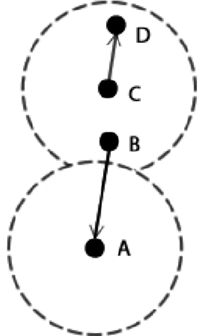
An Exposed Node is a node that cannot transmit to another node because it is sensing the commu-nication between other nodes, even though there is no mutual interference between the link that is established and the one that the Exposed Node wants to create. In Figure2.3node C is blocked by the communication between B and A (node C is exposed to B), although C and B could transmit at the same time without causing interference on A and D.
8 State of the Art
2.2 Solutions for Single-Hop Problems
The Hidden Node problem can substantially decrease the performance of a single-hop wireless network and thus require special attention when designing this type of networks. If one wants to minimize the existence of these kind of problems, solutions are proposed in [5] and some deserve a closer look and are discussed below.
Pure Contention Based These type of protocols have the advantage of using standard hardware with a single transceiver, which makes its implementation less expensive in relation to other types of protocols, and can be compatible with IEEE 802.11 if standard frames are used. They were divided into three groups: sender-initiated (when a connection is initiated by the sender), receiver-initiated, and hybrid. RTS/CTS exchange can be implemented in a pure contention based sender-initiated protocol (Figure2.4).
Figure 2.4: Example of a pure contention based sender-initiated protocol with RTS/CTS exchange [5]
Busy tone signal-based These protocols can be applied either with only one operating channel or multiple channels. These protocols are supported by a busy tone signal to control the medium informing if some node is communicating or not; its duration and location may vary from protocol to protocol. The big advantage is that busy tones can be recognized more easily than traditional MAC frames. An example is shown in the Figure2.5.
Multiple channel-based Multiple channel-based protocols use multiple channels to reduce the number of collisions, among other objectives. Three categories were established: with a common control channel, without a common control channel and a hybrid solution. With the use of multiple channels at the same time and with a common control channel the stations can define a channel for example to transmit only the RTS and CTS packets and another only to the exchange of data (Figure2.6). An example of a protocol not using a common control channel uses only one channel to transmit and another to receive packets. A hybrid protocol could be more complex using the two solutions already characterized.
2.3 Multi-hop Wireless Networks 9
Figure 2.5: Busy tone signal-based protocol [5]
Figure 2.6: Multiple channel-based protocol [5]
2.3 Multi-hop Wireless Networks
Like the concept normally used in wired networks, multi-hop can be implemented in wireless networks. A hop is one portion of a path (one link) between source and destination. If a packet needs to pass through one router for instance to reach its destination, then it is a two-hop-route. In wireless networks, making Access Points communicating with each other to create a network results in multi-hop wireless paths.
Different topologies can be implemented with the multi-hop concept but this work will focus on one specific topology: Wireless Mesh Networks.
2.3.1 Wireless Mesh Networks
Wireless Mesh Networks (WMNs) are networks organized in a mesh topology that is based on radio Access Points where most of them do not have a wired connection. WMNs (Figure 2.7) can be thought as an extension of a wired infrastructure. These networks are becoming extremely important due to their economic advantage and their ability to reach inaccessible points or zones compared to the wired networks. WMNs are characterized as being able to organize and configure
10 State of the Art themselves and also by their quick and easy deployment. Three types of devices in WMNs are defined in [6]:
• Mesh Points (in this document, the term Mesh Access Points - MAP, will be used): these nodes are the core of the network topology. They may connect with other MAPs and support the interconnection for the Mobile Nodes.
• Mesh Gateways (MG): these nodes are basically MAPs but with the major difference that they are the ones that provide the connection to wired networks and, in particular, to the Internet.
• Mobile Nodes (MN): these nodes connect to the network via MAPs. Although the name suggests its mobility a MN does not need to be mobile. Normally MNs are user devices such as laptops, smart phones, tablets, etc.
The WMN may be organized in two levels (core and access), as suggested by the above de-scription, or as a single-tier (flat) network with the end-stations playing the role of MAPs. A hybrid approach is also possible.
Stub Wireless Mesh Network
A Stub Wireless Mesh Network is a specific type of wireless multi-hop network. In this type of WMN most of the traffic is exchanged with external networks through a Mesh Gateway that has access to a wired network, and so the internal data traffic is low or even null. This means that the degree of traffic aggregation is greater in the nodes closer to the gateway.
A part of the problems of the WMNs come from the single-hop connections but they can get worse due to their multi-hop nature. In terms of the physical layer we can have: the substantially decrease of the Signal Noise Ratio (SNR) due to the higher number of interfering nodes; noise of antennas occupying the medium unnecessarily (omni-directional antennas against directional antennas); an inappropriate location of the access points causing interference or supporting the degradation of the signal; and the excess of energy used by the radios. In the Medium Access Control the problems of Hidden and Exposed Nodes can appear more often due to the higher number of nodes as said. But in WMNs, a new type of problem arises: the potential unfairness treatment of nodes, depending on their relative location in the network.
2.3.2 Fairness Problem
In a WMN, the network is not designed with rules that enforce a fairness treatment, nodes can be hindered in terms of data exchange. But if all the clients that use the networks are paying the same for the same service, they have the right to request equal Quality of Service.
In [8], three challenges of providing fairness in multi-hop wireless stub networks are enumer-ated:
2.3 Multi-hop Wireless Networks 11
Figure 2.7: Example of a Stub Wireless Mesh Network [7]
1. Contention discrepancies between wireless nodes: Following Figure 2.8, the sender of the flow 1 (A) is not in the carrier-sense range of the sender of flow 2 (B), although the receiver a is in the carrier-sense range of node B. So, B can detect the communications of a (for example, ACK or CTS of flow 1) and program flow 2 depending on the flow 1 in order to avoid packet losses, unlike A that is unaware of communications of B and tries to access the channel in the middle of the transmission of flow 2. This will lead to very high packet loss rates.
12 State of the Art 2. Traffic aggregation and multi-hop transmissions: In a multi-hop wireless stub network, intermediate MAPs may have to send data through multiple hops and for that they can be referred as Transit Access Points (TAPs). In the case of Figure2.9, there are two problems regarding fairness: not all MAPs have the same degree of retention, for example, as TAP4 is within transmission of TAP7, it transmits less frames than TAP1 and TAP2 to TAP3; the probability of lost frames increases with the rate of incoming traffic from mobile nodes attached to intermediate node (TAP3).
Figure 2.9: Traffic Agregation [8]
3. Selfish behavior of nodes: In this type of networks, we must also take note that not all nodes may work in a cooperative fashion. Often, the nodes may be managed by different independent entities that can lead to different packet forwarding schemes. Several mech-anisms have been proposed to encourage cooperation, for example, the reputation level of the nodes or other mechanism based in payments. What makes this a difficult problem to solve is the fact that revenue to maintain the operation of stub networks comes largely from mobile users.
Thinking of Stub WMNs, an interesting fairness reference model based on the next four con-straints is proposed in [9]:
1. The traffic generated by mobile nodes referring to a MAP in the network should be treated as a single aggregate flow independent of the number of micro flows of the mesh point. 2. The spatial reuse should be maximized. MAPs that do not cause interference to each other
may simultaneously transmit to take advantage of full capacity of the channel.
3. To avoid anomalies in the performance of IEEE 802.11, the fairness model uses the amount of time as a resource to be shared fairly instead of bandwidth.
2.4 Solutions for Fairness Problem 13
2.4 Solutions for Fairness Problem
Fairness in WMNs is a well-studied problem due to its importance when building networks that need to offer good QoS to its clients. In [8] the authors describe solutions that can be explored. Some of them are listed next.
Controlling the egress sending rates
In this solution, each MAP needs to measure the offered load of its mobile users and the effective capacity of the link connecting to an adjacent MAP. The offered load and the capacity are then exchanged between MAPs periodically. The end-to-end throughput is then computed based on the four fairness constraints stated in the last section. Although not needing to modify queuing, forwarding and MAC layer contention in these mechanisms, it is very difficult to measure the real capacity of the networks and the information exchanged between MAPs increases the load of the network.
Modifying the forwarding and MAC layer contention behavior
Controlling and modifying the queuing, forwarding and MAC layer contention behavior, can also enforce the fairness model stated before. Some approaches can be followed as implement sepa-rately queues for traffic exchanges with mobile nodes and MAPs or, allocate more extra bandwidth via MAC-layered QoS mechanisms. This solution requires changing MAPs operations and some of them can involve higher hardware requisites.
Game theoretical approach
Treating the problem of fairness as a game is proposed in [8]. Tokens and credits are created and earned by each mesh point when transferring a unit of data traffic to an adjacent MAP. To earn real income (paid by mobile users) the MAPs have to accumulate enough credits. This solution could prevent or minimize the problem of the selfish behavior of nodes previously mentioned.
Scheduling of wireless links
The scheduling of slots in time-division multiplexed links is an idea also discussed in [8] to achieve fairness. In this solution the idea is to schedule time slots in a way that non-interfering mesh points transmit at the same time. The main objective is to maximize the overall throughput.
Criteria for fair scheduling have been classified in [10] and are briefly described.
Hard Fairness In this type of criterion, each node is guaranteed the same amount of communi-cation time. The only problem is that if time slots are reserved for a node that has no data to send, time ends up being wasted. This can lead to an overall very low throughput.
14 State of the Art Max-min Fairness in WMNs Max-min fairness is one of the methods that can be applied in a wired network to provide fairness and has been already extended to wireless networks focusing only in a single-hop connection. In this method the resources are allocated in ascending order of the requested amount. If there are no available resources to the remaining requests the resources are divided identically. This means that nodes that require fewer resources will receive a larger proportion of what they need (or even the total amount); nodes not fully satisfied receive the same amount (the so-called fair share). This type of criterion works better in situations where there are not large differences in resources requested by the nodes. Applying this method to multi-hop flows in WMNs is complicated for two reasons [11]: the effect of intra-flow contention must be taken into account with respect to upstream and downstream, which may lead to a faster flow than an other; and the effect of inequality of channel capacity. The redefinition of the Max-min fairness criterion tries to improve the throughput of the connection with these problems by allocating the same amount of time of the channel rather than allocating the same rate for each flow.
Proportional Fairness Allocates resources proportionally to a certain characteristic in the net-work. It is used for example when we want to give priority to nodes nearest the gateway. In this example the network will benefit in terms of resources used because less links will be active re-garding the proximity to the gateway. The strength of proportionality can be controlled depending on a proportionality factor seen in the following equation:
R = 1
cb (2.1)
R is the resources allocated to the node; c is the characteristic to which priority is associated, c > 0;b is the proportionality factor b > 0
Maximum Throughput “Whichever node requires the most resources, or can transmit data or can transmit the fastest or most data gets access to the resources first” is quoted from [10]. As the name of this criterion implies, it ensures maximum throughput in the network. The problem is that the nodes that have lower priority are ignored and if too much time is spent in queues packets are dropped which may even lead to starvation of some nodes.
As seen, there are several proposals to achieve fairness in a network, with different degrees of complexity. Depending of the perspective of fairness that one can adopt in a network, some criteria can be more appropriate than others.
2.5 Spatial Reuse
In a WMN that has a large number of MAPs covering a wide area, some of them are not in In-terference Range of each other and so do not affect the respective communications regarding data packets and ACK packets for example. By paying attention to this aspect, some rules can be implemented to improve the performance of the network regarding the overall throughput, since
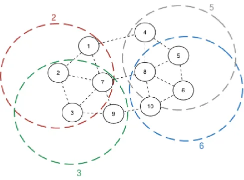
2.6 WiFIX 15 some MAPs could benefit from the unused space to communicate. In the example illustrated in Figure2.10, nodes 2 and 3 are communicating. Since they do not interfere with the communi-cations between nodes 5 and 6, these last nodes can be authorized to communicate between each other.
Techniques that could be used when thinking of exploiting spatial reuse are presented in [3]. Transmit Power Control Controlling the power transmitted by the nodes can be seen as a sim-ple solution at first but in fact it can be very challenging. On one hand, reducing the transmission power, the number of nodes competing for wireless channel access within the transmission range is smaller and so the number of collisions is reduced, but the average number of hops increases. On the other hand, as the number of transmitting nodes increases, the overall SINR might degrade because of the increase of aggregate interference.
Importance of power control in wireless networks according to [3]:
• Transmission power determines the transmission range which can affect the connectivity and network topology.
• Energy efficiency of the nodes (sometimes nodes can be energy constrained) • High power of transmission can cause unnecessarily interference in the network.
Rate Adaptation The idea of the Rate Adaptation Mechanism is to select appropriate transmis-sion rates according to the channel condition. If the conditions are good, higher rates should be selected to improve efficiency, if there are channel impairments, the rate should be decreased to improve reliability. This can be applied by the transmitter (transmitter-based) or by the receiver (receiver-based).
2.6 WiFIX
Wi-Fi network Infrastructure eXtension (WiFIX) proposed in [1] by Rui Camps et al., is a solution for Wireless Mesh Networks based on IEEE 802.1D bridges and a mechanism of self-organization of the network based on a single-message protocol. WiFIX advantages are notorious like config-uring the network automatically, making possible the coexistence of the IPV4 and IPV6 protocols or being a solution that can support any 802-based technology.
2.6.1 Active Tree Topology Creation and Maintenance
The mechanism used to create one tree with its root at the Master MAP as root is called Active Tree Topology Creation and Maintenance (ATCM) (Figure2.11). To create the tree, a refresh message (update) topology (Topology Refresh, TR) (Figure2.12) is sent by the master MAP periodically and the other Mesh Access Points forward it to the entire network. This message allows each MAP to select the best parent that has connectivity to the master MAP (in terms of hops). MAPs chosen
16 State of the Art
Figure 2.10: Example of Spatial Reuse
as parents are informed about who chose them and then is established an Eo11 tunnel between parent and son. The TR message also informs who is the Master MAP.
Figure 2.11: WiFIX: Establishing Virtual Links [1]
2.6.2 Eo11 Encapsulation
WiFIX needs 4 addresses: original source and destination addresses and intermediate source and intermediate destination addresses for each hop. To do so, a new header was created to allow the inclusion of two more addresses besides the two addresses on the original header(Figure 2.13). The inner header is filled with the original MAC addresses and Ethertype and the outer header with the MACs of the next hop and the current node, and the Ethertype with Eo11 Encapsulation.
2.6 WiFIX 17
Figure 2.12: WiFIX: Topology Refresh Message [1]
With all this, the intermediate MAPs only have to change the outer header to forward the frames without touching the original source and destination addresses.
Figure 2.13: WiFIX: Eo11 Encapsulation [1]
2.6.3 IEEE 802.1D bridges
The forwarding rules in WiFIX are basically the same as those used by the 802.1D bridges where it can be thought that the ports in this algorithm are in fact the endpoints of tunnels created. When getting a unicast frame, a pair of addresses has to be added to the bridge forwarding table:
• If the unicast frame destination address exists in the bridge forwarding table, the frame is sent to the tunnel endpoint specified in the bridge forwarding table
• If the unicast frame destination address does not exist in the bridge forwarding table, the frame is sent to all tunnels, except the one the frame was received from
Similarly to 802.1D bridges, upon receiving a broadcast frame the bridge will send the frame to all the "endpoints" of the tunnels except the one where the frame was received from. But with this approach, it is clear that some nodes can receive more than one copy of the frame which leads to a high inefficiency. So the mechanism has been optimized with an algorithm called Duplicate Processing Algorithm (DPA). Using information from the tree topology, the algorithm only allows the nodes having more than one neighbour to forward the frame and the nodes that have a single connection if they are the origin of the frame or the frame is entering the mesh through it.
18 State of the Art 2.6.4 Implementation in LINUX
WiFIX is implemented in the Linux Operating System taking advantage of an 802.1D software bridge and tools to create virtual interfaces (taps). The tunnels that every node creates with its children and parent node are implemented using taps that behave like Layer-2 Ethernet from the upper layers point of view. Conceptually, WiFIX is situated between the NIC and the taps (Figure
2.14) to process all the frames that could be received from or sent to those interfaces.
Figure 2.14: WiFIX: Interaction with its peer Modules [1]
When receiving a frame from the NIC, the WiFIX daemon has to verify the type of the frame. A configuration frame is processed in the daemon and can or not be sent to the NIC. When it is a data frame, firstly it is verified whether it comes from a neighbour (otherwise the frame is dropped), then the first header (Eo11 header) is removed and the rest of the frame is sent to the tap that corresponds to the source neighbour. This frame goes to a 802.1D bridge that decides where to send the frame. When the daemon receives a frame from a tap, it adds an Eo11 header that has the addresses of the actual MAP and of the next neighbour MAP that corresponds to the address associated with the tap that the frame was read from.
The auto-configuration of a WiFIX Mesh Network with the ATCM (Active Topology Creation and Maintenance) mechanism is a key aspect of WiFIX and has to be described and explained for a better understanding of some parts of this work.
A TR Message (Figure2.12) is sent by the Gateway MAP (in WiFIX it is called Master MAP) to the NIC in broadcast and is forwarded by the other MAPs after changing some parameters of the message. The MAPs wait a predefined time interval to receive all the TR messages that they can. When the waiting time runs out, they can choose the upper neighbour that has the best route to the Master MAP in terms of number of hops. When a MAP chooses its upper neighbour, the WiFIX daemon creates a new tap and adds it to the bridge, modifying too a table that keeps correspondences between the taps and the addresses of the neighbour nodes. A MAP knows that it was chosen as upper neighbour when it receives a TR message with its address in the Parent Address field. The process of adding a tap is now done in the same way in the upper neighbour. With these steps, a tunnel between a MAP and an upper neighbour is established.
2.7 Smart Grids as an application example 19
2.7 Smart Grids as an application example
A Smart Grid is a electrical grid that has associated a communications system that supports the transmission of information for several purposes (metering, monitoring and control). Such infor-mation is not only useful for the electric utilities and market stakeholders but also to end users, who can manage energy consumption in a more efficient way.
One solution studied in [12] for a communication infrastructure is based on a wireless mesh network where each house has an access point that is connected with other neighbour access points. Then, with a forwarding packet scheme, the informations must arrive to the electric company com-munication infra-structure (PT) as seen in the example on the Figure2.15. As the information that
Figure 2.15: Smart Grid Scenario [13]
passes through the communications network is very important and must not be corrupted, the big objective of Smart Grids is to design an architecture that must be secure and reliable, supporting two-way communications from the houses to the operations center of the electrical company.
802.11 Wireless Mesh Networks with the organization characteristics of WiFIX could be one of the best solutions for this application scenario comparing with cellular and WiMAX systems, fulfilling the following requirements:
• Coverage: Efficient and affordable, even in remote areas.
• Capacity: Scalable high bandwidth capacity that accommodates networks of thousands of devices.
• Control: Full network command that is important during disasters.
• Capability: With additional mechanisms could be secure, reliable, with portable equipment and ready to customize.
20 State of the Art • Cost: Capital expenditures are recoverable.
Wireless Mesh Network versus PowerLine Communications
PowerLine Communications (PLC) is a technology that uses the electric power network to carry data. The big advantage of this technology for data transferring is that it could take advantage of the common electrical infrastructure that is already installed almost everywhere providing energy distribution to end customers.
Comparing with PLC, WMNs have some advantages that make this technology a good choice for Smart Grids. We may be led to think that since PLC is a technology that reuses the electric infrastructure already deployed we can rule out other alternatives to connect smart meters but this technology has its own problems.
Some problems like the noise level and electromagnetic interference, as well as derivations and ramifications in the electric feeders served by secondary substations make this solution not very tempting.This could lead to corruption and loss of data, which may be critical for some control applications. WMNs may overcome these problems and offer a flexible, efficient and scalable solution at an affordable cost, for current and future applications that are not restricted to metering.
Chapter 3
Specification of PACE Mechanism
As already mentioned, WMNs can be used in a diversity of application scenarios and even extend some infrastructures where cable connections are unfeasible or costly; as such, WMNs can play a role in providing access to a major network, like the Internet. However, as seen, this type of networks can only be a solution if some inherent limitations could be overcome or, at least, minimized. The current WiFIX solution does not take into account some critical problems from the controlling data exchange point of view.
Concerning the studied problems of WMNs, a solution was proposed to cope not only with the problems associated with single-hop connections but also with those that are inherent to the multi-hop nature of WMNs. The solution implemented was called PACE and is in fact a simple multi-hop scheduling mechanism for single-radio 802.11-based stub Wireless Mesh Networks.
Having the objective of letting only one station to communicate at each time, PACE [7] is a centralized scheduling mechanism that provides coordinated access among nodes in a wireless network to prevent collisions, without the need for explicit synchronization among node. Since in a stub network most of the traffic is exchanged with external networks and thus goes through a gateway, the best choice for locating the scheduler is the gateway. Although not considered in this work, a distributed version of the mechanism is also possible, by imposing the circulation of a token on a logical tree.
3.1 Operation
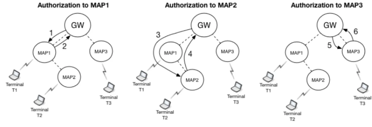
Limiting the transmissions to a single MAP at a time, PACE helps in the deployment of an efficient and fair WMN. Let us assume the scenario of Figure3.1. The Gateway MAP takes control and the first authorization turn is given to MAP1. So the Gateway MAP sends a packet to one of the terminals that is attached to MAP1, for example Terminal 1 (T1). That packet, when received by MAP1, is then forwarded to T1. At the same time, MAP1 is now ready to answer and can send only one packet, which was previously sent from one of its terminals and was placed in a queue.
When receiving a packet from the MAP that is waiting for or has already waited for a de-termined timeout (the packet can be lost), the Gateway MAP now changes the authorization turn
22 Specification of PACE Mechanism and the process is repeated with another destination MAP, for instance MAP2. In a fair network this is done until all the MAPs in the network have had the opportunity to transmit one packet, in this case MAP3 is the last. Then it restarts from the first destination MAP and continues in anew cycle. In case no data is available, a Poling Control Packet (PCP) is sent to continue the process, substituting the missing data whether is the Gateway MAP or a normal MAP the sender.
Figure 3.1: Exemplification of PACE Mechanism Authorizations
3.2 Queues
The operation of this mechanism is based on queues that have to be created at the Gateway MAP and at the MAPs (exemplification in Figure 3.2). At the Gateway MAP, there must be a queue for each MAP in the Mesh Network, to store the packets for the terminals that are attached to the corresponding MAP. At the MAPs, only one queue is needed, which stores the packets that were sent by the attached terminals and are waiting to be forwarded to the Gateway MAP in the Mesh Network.
With this queues the packets that must be transported in the Mesh Network have a place to wait until they are scheduled. The number of packets that can be held in the lists depends on the configuration that is settled by the network administrator.
3.3 Polling Control Packet
Some kind of control message has to be sent when the turn of a MAP happens and there is no packet to send from the Gateway MAP to the polled MAP or in the reverse direction.
The Polling Control Packet (PCP) is a packet that is sent when there is no data packet in the waiting list associated with the next MAP to be scheduled; thus, it has no payload.
Following the example in Figure3.3: if the Gateway MAP does not have packets to send to MAP2 in case it would jump to MAP3, MAP2 would have to wait another cycle to send data in its waiting list (if any). This would cause an unfair treatment, and thus Gateway MAP sends a PCP to give authorization to MAP2. Similarly, if a packet was sent from the Gateway MAP to MAP3
3.3 Polling Control Packet 23
Figure 3.2: PACE Lists Scheme
and MAP3 had not a packet to send, a PCP shoul be sent by MAP3 to the Gateway MAP to return control.
24 Specification of PACE Mechanism
3.4 PACE and the WMNs Problems
With the implementation of PACE scheduling mechanism it is possible to build a network and prevent or minimize some WMNs problems. When used with WiFIX, PACE cannot completely prevent the hidden node problem.
Relatively to data exchange the hidden node problem does not happen at all because only one node is sending a packet in the whole network at a time, whether it is a source/destination or an intermediate MAP along the path, so there are no frame collisions. Problems occur because control packets required for WiFIX operation, like topology packets, cannot be treated by the PACE mechanism due to the inconvenience of waiting or being lost; this could lead to a partial or total disruption of the network. With this, WiFIX packets and data packets can sometimes be sent at the same time and cause collisions as shown in Figure3.4. However, these collisions are residual, since control traffic is reduced. Anyway, such collisions are handled by the underlying CSMA/CA protocol, which is kept, since PACE runs over standard IEEE 802.11 cards.
Figure 3.4: WiFIX Packets and Data Packets Collisions
As PACE can schedule all MAPs in the network in a round robin way, it is possible to achieve a completely fair operation where all MAPs have the same opportunity to send and receive data. This can be achieved by creating for example a circular list with all MAPs in the network; each one is chosen at a time and when all MAPs are chosen, a new cycle is initiated.
Besides that, the scheduling mechanism can be modified to give more or less priority to chosen nodes, based on some criterion (for example, number of terminals per MAP, measured average traffic per MAP or size of average queue per MAP, which may require the exchange of some control information between the MAPs and the Gateway).
Chapter 4
Work Developed
In this chapter is described how the actual solution of WiFIX was modified to receive the PACE Mechanism and then how that mechanism was applied.
As WiFIX was oriented for the Linux operating system, all the work was made with that purpose too, in C language. Remembering how WiFIX works, it is situated, conceptually, between the virtual interfaces (taps) and the NIC (Network Interface Controller) as could be seen in figure
2.14, that operates with IEEE 802.11. In this position, WiFIX is capable of read the frames that receives from the NIC or from the taps, process them and write them in which interface it decides is the destiny. A tap can be thought as an entry or exit of a Eo11 tunnel established between neighbour MAPs and is saw from the upper layers as an Ethernet layer 2 device.
4.1 Modifications to WiFIX to support PACE
In the original version of WiFIX, there are no routes in the network before data is injected and so, when a MAP joins the network not having the Master MAP as its upper neighbour, the Master MAP does not know if a new MAP joined the network and how to reach it. Thus, the PACE mechanism could not work correctly because waiting lists are not created and the new MAP is not scheduled to transmit data packets. Some modifications in the original WiFIX had to be performed to make the Master MAP aware that a new MAP joined the network.
4.1.1 New MAP Message
When a MAP joins the network, the first thing it has to do is to inform all the MAPs above that it is a new MAP. The new MAP sends a message (Figure4.1) to its upper neighbour and the message is forwarded all the way to the Master MAP. With this, intermediate MAPs can create routes to the new MAP and the Master MAP adds the corresponding new address to its addresses list.
This message is created like a topology message, that was already implemented in the original version of WiFIX, to take advantage of the forwarding process of this kind of packets. These packets, when received from an intermediate node on the path between a MAP and the Master
26 Work Developed MAP, are always forwarded to the upper neighbour until they reach the Master MAP that processes them. The second header of this packet is constructed with this essential information:
• Ethertype: Eo11
• Address 2: Address of New MAP • Flag: Topology Message
Figure 4.1: New MAP Message
4.1.2 New Terminal Message
The same process is important to occur when a new terminal is attached to a MAP. A new terminal information packet is also sent with the objective of informing Master MAP that a terminal is attached to a specific MAP in the WiFIX Mesh Network. This message (Figure4.2) is also created like a topology message to again benefit from its forwarding properties but now we have one more important field, the Parent MAP of the terminal:
• Ethertype: Eo11
• Address 2: Address of New Terminal • Flag: Topology Message
• Address 3: Address of Parent MAP of the Terminal (Current Node)
Figure 4.2: New Terminal Message
With the Address 3 field, the Master MAP can associate the Terminal to a MAP and this will be important when adding packets to the waiting lists of MAPs.
4.2 Implementation of PACE 27
4.2 Implementation of PACE
The polling scheme was first adapted and then carefully integrated in the original version of WiFIX only changing the general process of sending and receiving packets.
4.2.1 List of MAPs in Master MAP
To know which is the MAP that the Master MAP will schedule, a circular list is created (Figure
4.3). It is a list with all the MAPs in the WiFIX Mesh Network and is accessed to return the first MAC address that it contains and right after that the same MAC address is added to the list again, now in the last position. With this we can guarantee that all the MAPs are scheduled in a fair way. This MAPs list is defined in C as a struct:
1. int first; 2. int last; 3. int capacity; 4. int quantity;
5. unsigned char map_to_send[6]; 6. unsigned char nb_to_send[6];
7. mac_addresses maps_in_gw[MAXMAPSONMESH].
The first, second, third and fourth integers are defined to assist in the operation of the list. The fifth element saves the MAP that has the authorization to send and the sixth is the down neighbour of the Gateway that is in the path towards the scheduled MAP. Finally, the last element is a struct that contains all MAPs and the corresponding down neighbours of the Gateway in the WiFIX Mesh Network:
1. unsigned char mac_address[6]; 2. unsigned char nb_address[6].
4.2.2 Packet Queues
When a node, no matter whether it is the Master MAP or a MAP, has to send a packet through the WiFIX Mesh Network and has not given permission to do it, it has to store the packet while waiting for its turn. To do that, queues were created (Figure4.4) and are accessed when the node is scheduled to send the packet. A waiting list is defined in C as a struct and is composed of:
28 Work Developed
Figure 4.3: List of MAPs in Master MAP
2. unsigned char packets[MAXPACKETFOREACHMAP][FRAMELENGTH]; 3. int first;
4. int last; 5. int capacity; 6. int quantity;
7. unsigned char packet_to_send[FRAMELENGTH]; 8. int packet_size[MAXPACKETFOREACHMAP].
The first variable saves the MAC address of the destination MAP of all packets in that list. As the approach of this work is based on Stub WMNs, a normal MAP only has to send packets towards the Master MAP so, this variable is not used and only a general queue is created in a normal MAP implementation. The second is the set of packets stored in the queue. The third, fourth, fifth and sixth are integers to assist in the operation of the list. The seventh is a place to save the next packet to send and the eight saves the sizes of the packets that are stored in the list.
4.2 Implementation of PACE 29 4.2.3 Polling Control Packet (PCP)
To implement the PACE Mechanism, it was necessary to create a new packet that controls the polling process when there are no data packets to send whether the node is the Master MAP or a MAP. This packet (Figure4.5) is basically a data packet but with the destination address in the second header depending on the respective destination MAP.
So, the relevant information of the packet lies on the second header: • Ethertype: Eo11
• Address 1: Destination MAP (if it is created by the Master MAP) or UP Neighbor (if it is created by a MAP)
• Address 2: Current Node Address
Figure 4.5: Polling Control Packet
4.2.4 PACE Mechanism
The implementation of PACE mechanism had three major sections: • Process the received frames from the real interface (NIC)
• Process the frames that come from a tap and put them in the waiting list • Send the frames in the waiting lists to the real interface
4.2.4.1 Process the received frames from the real interface (NIC)
The frame received from the NIC is read by the WiFIX daemon to know how it should behave. The process is described next and is summarised in Figure4.6.
Master MAP
When a Data Packet is received from the NIC, the first test is to see whether the packet comes from an upper neighbour; if this is false, the packet is immediately forwarded to the bridge because from the point of view of a Stub WMN it is a communication from a downstream MAP. Otherwise (i.e., the packet comes from an upper neighbour), the MAP checks if it is a PCP packet and is authorized
30 Work Developed to send a new packet if this is true; when it is not a PCP, the MAP verifies whether the packet is addressed to a terminal attached to it: if so, the packet is forwarded to the bridge and the MAP is authorized to send a new packet; if not, this means that it is not a communication with that MAP and the packet is forwarded to the bridge.
MAP
When a Data Packet is received from the NIC in a MAP, the first test is to see if the packet comes from an upper neighbour: if it is false, the packet is immediately forward to the bridge because in the point of view of a Stub WMN it is a communication from other MAP; otherwise is tested if it is a PCP packet and the MAP is authorized to send a new packet if it is true. When it is not a PCP, is tested if the packet is to a terminal attached to the MAP: if it is, the packet is forward to the bridge and the MAP is authorized to send a new packet; if not it means that is not a communication to that MAP and the packet is forward to the bridge.
Figure 4.6: Procedure when packet is received from NIC
4.2.4.2 Process the frames that come from a tap and put them in the packet queues
A frame received from a tap cannot simply go directly to the NIC. Before, it has to stay in a queue until it is scheduled for transmission. The process is described next and is summarised in Figure
4.2 Implementation of PACE 31
4.7.
Master MAP
The Master MAP has queues created for all the MAPs in the WiFIX mesh network and has also a list of all terminals in the network. If it receives from the external network a frame such that the destination address is a terminal in its terminals list, it inserts the frame in the queue of the corresponding MAP to which the terminal is attached. If the original destination is not in the list, it simply drops the frame.
MAP
The MAP has only one queue for frames (to be sent towards the Gateway MAP). So, if it receives a frame such that the original source of the frame is a terminal attached to it, it inserts the frame in the general queue. If it is not from a terminal, it sends the frame to the real interface because it must relay it to the upper neighbour MAP.
Figure 4.7: Procedure when packet is received from tap
4.2.4.3 Send the frames in the packet queues to the real interface
Now, only when the node is scheduled, it can send a frame to the NIC (unless a Normal Node is an intermediate node). The process is similar in the Master MAP and a MAP but the Master MAP has to select a MAP and a packet from the respective queue. A circular list is accessed to know that.
Every time the list is accessed the first MAP address is selected and then is moved to the last position on the list. In a MAP there is only one general waiting list to access. Then the Master MAP or MAP will send the frame in the selected list. If the list is empty, a PCP is sent. This process is described in Figure4.8.
32 Work Developed
Chapter 5
Results and Discussion
With all the modifications introduced into the original WiFIX version and the correct implemen-tation of the PACE scheduling mechanism, some experiences were performed with the objective of evaluating this new version. This chapter is divided in three sections: it starts by presenting the equipment used and how it was configured; the second section reports the experiments performed and the evaluation of the new WiFIX with PACE scheduling mechanism; and finally, the problem of throughput reduction associated with the PACE implementation is analyzed and discussed.
5.1 Equipment and Configurations
For the practical tests four Alix 3D3 system boards were used each one with a MikroTik Router-BOARD R52n-M miniPCI network adapter (Figure5.1and Figure5.2respectively). For a singular test, explained later in section5.3, two 5 dBi omni-directional antennas were also used.
The Operating System chosen to be installed in the boards, besides being Linux because of the WiFIX implementation, had to properly work in the boards provided and be a reference in the networking field. OpenWrt is one of the systems that fulfills the requirements and its last version, 12.09 was chosen. Drivers to support the network adapter and packages needed to run the WiFIX solution were installed and are listed in AppendixB.
Figure 5.1: Alix 3D3 system board Figure 5.2: MikroTik RouterBOARDR52n-M miniPCI network adapter 33
34 Results and Discussion In all the experiences carried out, the boards were configured in channel 147, frequency 5.745 GHz, 802.11a standard. This frequency was chosen because it was not used in the laboratory environment and it was important to avoid as much interferences as possible, in order to obtain the best results in terms of throughput and packet losses. The transmit power was not changed during the tests and remained configured at 50mW.
Some programs were installed with different objectives: Iperf was used to generate real traffic and the throughput values were measured with IPTraf and Bmon.
5.2 PACE Mechanism Experiments and Evaluation
For this experiments the four boards that were available were used: one was configured as Master MAP and the other three as Normal MAPs. The topology adopted with the purpose of comparing the results of the simulated version was the one studied in [7] and is represented in Figure5.3.
Figure 5.3: Tested topology
Since the experiments were done without antennas, the range of the wireless adapter was very restricted; thus, the boards were set in a structure that could allow the communications between them. This structure can be compared with a building with four equally spaced floors with a board on each floor, as exemplified in Figure5.4. As the boards could hear each other and it was necessary to follow the topology already demonstrated, filters were applied in the solutions tested to only allow a board accepting packets from the immediately below board and from the above ones. If these filters were not applied, the MAPs would naturally chose the MAP with less hops to the Master MAP and the topology would certainly be different because all of them would sense the Master MAP.
Figure 5.4: Building of real position of the boards
The tests of the new version developed were done in two stages for two reasons: to verify if the critical parts of the implementation were well developed; and to verify and measure the damages that the non-implementation of parallelism between reading and writing the NIC’s socket and TAP’s sockets would originate.
5.2 PACE Mechanism Experiments and Evaluation 35 First Stage: The objective was to see if there were not simultaneous data transfers in the net-work, in other words, if the MAPs were only sending packets when they had to, the polling mechanism.
Second Stage: After the first stage had been successfully completed, it was necessary to test if the packet queues were working properly receiving and releasing packets from TAPs. With this stage it would be possible to observe the effect of non-implementation of parallelism. Following the paper that presents the simulation results of WiFIX with PACE scheduling mechanism [7], it was important to measure how the throughputs were affected depending on different characteristics of the network. Based on the same paper, the following cases were estab-lished:
• Case 1: a single MAP is active and polled and traffic is bidirectional. This allows determin-ing how the distance in terms of hops to the gateway affects performance.
• Case 2: similar to case 1 but with upstream traffic only. The downstream traffic is a control packet and this allows determining the effect of not embedding the poll signal in data. • Cases 3 and 4: similar to cases 1 and 2, respectively, but now all nodes are polled (full
polling). These cases allow observing the effect of polling inactive nodes.
• Case 5: all four MAPs are active and traffic is bidirectional. This allows observing the fairness behavior.
• Case 6: similar to case 5, but with upstream traffic only.
5.2.1 First stage: MAPs waiting for their opportunity to communicate
As defined in the specification of PACE, the Master MAP has the function of giving the turn to a MAP to communicate, as long as it is subscribed in the MAPs list of the Master MAP. This stage gave the opportunity to test if the New MAP message was well received at the Master MAP and if the MAC Address of the new MAP was inserted in the List of MAPs of the Master MAP. It was possible to check then if the Master MAP was giving equal communicating opportunities to the MAPs and if the MAPs were only sending packets when it was their turn.
For this test, to prevent any interference of pieces of C code that could not be well imple-mented, some functions of WiFIX that were not necessary were turned off. The process of adding neighbours and creating tunnels with TAPs was maintained but it was not possible to receive and send data packets through the tunnels. This process was substituted with static code that was pos-sible to create because the topology for the experience was known and also static. This version of WiFIX also had previously hard coded packets of 1400 bytes to simulate real traffic when it was asked. Figure5.5represents how these modifications affected the original operation of the WiFIX modules.
![Figure 2.4: Example of a pure contention based sender-initiated protocol with RTS/CTS exchange [5]](https://thumb-eu.123doks.com/thumbv2/123dok_br/15710248.1068852/25.892.241.612.489.670/figure-example-contention-based-sender-initiated-protocol-exchange.webp)
![Figure 2.5: Busy tone signal-based protocol [5]](https://thumb-eu.123doks.com/thumbv2/123dok_br/15710248.1068852/26.892.191.726.152.336/figure-busy-tone-signal-based-protocol.webp)
![Figure 2.7: Example of a Stub Wireless Mesh Network [7]](https://thumb-eu.123doks.com/thumbv2/123dok_br/15710248.1068852/28.892.230.715.146.553/figure-example-stub-wireless-mesh-network.webp)
![Figure 2.9: Traffic Agregation [8]](https://thumb-eu.123doks.com/thumbv2/123dok_br/15710248.1068852/29.892.275.572.345.567/figure-traffic-agregation.webp)
![Figure 2.12: WiFIX: Topology Refresh Message [1]](https://thumb-eu.123doks.com/thumbv2/123dok_br/15710248.1068852/34.892.152.777.148.332/figure-wifix-topology-refresh-message.webp)
![Figure 2.14: WiFIX: Interaction with its peer Modules [1]](https://thumb-eu.123doks.com/thumbv2/123dok_br/15710248.1068852/35.892.266.580.356.518/figure-wifix-interaction-peer-modules.webp)
![Figure 2.15: Smart Grid Scenario [13]](https://thumb-eu.123doks.com/thumbv2/123dok_br/15710248.1068852/36.892.278.662.430.702/figure-smart-grid-scenario.webp)