Nonlinear Processes in Geophysics (2003) 10: 437–440
Nonlinear Processes
in Geophysics
c
European Geosciences Union 2003
On the Earth’s magnetic field and the Hall effect
J. E. Allen
University College, Oxford, OX1 4BH, UK
Received: 12 June 2002 – Revised: 14 October 2002 – Accepted: 15 January 2003
Abstract.In a recent paper de Paor put forward a new theory of the Earth’s magnetic field that depended on the Hall effect as an energy transfer mechanism. The purpose of this paper is to demonstrate that the mechanism invoked is unimportant except in certain gaseous plasmas.
1 Introduction
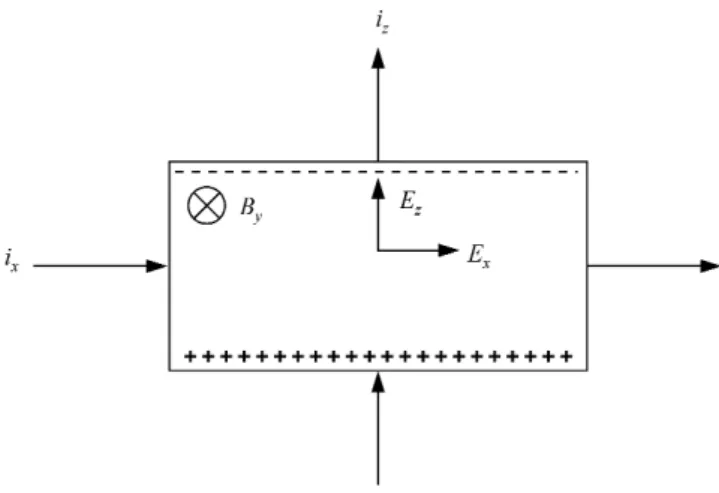
A new theory of the Earth’s magnetic field has been put for-ward recently that depends on the Hall effect (de Paor, 2001). In this theory the Hall effect is called upon as a mechanism for transferring a flow of electrical energy from one direc-tion to another orthogonal to the first. This is illustrated in Fig. 1, which shows a sample of conducting material placed in a magnetic field; de Paor (loc. cit.) considers that a flow of energy in the x-direction is transferred, in part, to the
z-direction. It is shown in the present paper that, although such a process does take place, the effect is infinitesimally small in solids and liquids. It is extremely unlikely, there-fore, that the mechanism is important in the production of the Earth’s magnetic field.
2 The Hall effect
We shall start by presenting a simple theory of the Hall ef-fect (Kittel, 1996; Solymar and Walsh, 1997). Suppose that we have a uniform electric fieldEx in thex-direction and a
magnetic fieldB in the y-direction. The electrons drifting in thex-direction will experience a Lorentz force in thez -direction. Let us denote the electron drift velocities in the
y andz-directions byu, ν, respectively. The mean force in thex-direction will be(−e)uBand the mean force in thex -direction will be(−e)(Ex−νB). In this notation eis the
magnitude of the electronic charge. Thus we obtain the fol-Correspondence to:J. E. Allen ([email protected])
Fig. 1.To illustrate the Hall effect, the charge carriers are assumed to be electrons, which flow in the positivez-direction (in the Hall circuit).
lowing momentum balance equations, for the two directions.
(−e)(Ex−νB)=muνc (1)
and (−e)uB=mννc (2)
whereνis the collision frequency. From the second equation we have
ν= − eB
m
τ u, where τ =1/νc
or ν= −(ωτ ) u (3)
whereωis the electron gyrofrequency(eB/m). Substitution in the first equation gives
u= − 1
1+(ωτ )2 eτ
m Ex
or u= − 1
438 J. E. Allen: On the Earth’s magnetic field and the Hall effect
Fig. 2. (a)the current densities due to ExandBy,(b)the current densities due
toEz andBy. On open circuitEz =
(ωτ ) Ex; at maximum power output in
the Hall circuitEz=(ωτ ) Ex/2.
whereµis the mobility. The quantity(ωτ )is known as the Hall parameter and the expressionµ/ 1+(ωτ )2
is some-times referred to as “the cross-mobility”.
In addition we have
ν= ωτ
1+(ωτ )2 µEx (5)
The current in thez-direction is known as the Hall current. The resulting current densities are given by the following two equations, wherenis the electron density,
jx=
1
1+(ωτ )2 µneEx (6)
and jz= −
(ωτ )
1+(ωτ )2 µEx (7)
We must now consider the effect of impedance in the Hall current circuit. The above calculation applies only when there is no electric field in thez-direction; in general such a field will be developed as shown in Fig. 1 (c.f. de Paor, 2001). The current density in thez-direction due to Ez is
indicated in Fig. 2; the associated Hall current in the x -direction is also shown and augments that due toEx. The
total current density in thex-direction is now
jx=
neµ
1+(ωτ )2
Ex+(ωτ ) Ez
(8) and that in thez-direction is
jz=
neµ
1+(ωτ )2
Ez−(ωτ ) Ex (9)
If the current in the z-direction is zero, due to a high impedance circuit,Ez =(ωτ )Ex andjx =neµEx, i.e. the
magnetic field has no effect on the current flow. The electric and magnetic forces in thez-direction are balanced.
The input power to the system is given, in general, by
Wi =
neµEx
1+(ωτ )2
Ex+(ωτ ) Ez (10)
where we have considered a unit volume, for convenience. The output power is given byWo = −jzEzbecause current
flows in the negativez-direction, the flow of electrons being upwards.
Wo=
neµEz
1+(ωτ )2
(ωτ ) Ex−Ez (11)
For a given field in thex-direction, the output power is a maximum whenEz=(ωτ )/2Ex.
In this case
Wom=
neµEx2
1+(ωτ )2 · (ωτ )2
4 (12)
In a solid or a liquid(ωτ )≪1, so that the maximum power available would be
Wom=neµEx2 ·
(ωτ )2
4 (13)
Under these conditions the input power and dissipation are given by
Wim=neµE2x
1−1
2(ωτ ) 2
(14) and Wdm=neµEx2
1−3
4(ωτ ) 2
(15)
It is seen thatWimandWdmare both equal toneµEx2, to a
high degree of approximation. It should be noted that the subscripts ofWim andWdm refer to the situation when the
output power has its maximum value.
It is of interest to examine the case where (ωτ ) ≫ 1, which is possible for a gaseous plasma. In this case we have the following results
Wom=
neµEx2
4 (16)
Wim=
neµEx2
2 (17)
Wdm=
neµEx2
J. E. Allen: On the Earth’s magnetic field and the Hall effect 439
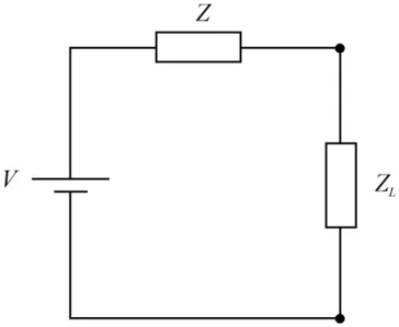
Fig. 3. The equivalent Hall current circuit. V = (ωτ ) Exb, Z =
1+(ωτ )2
neµ ·ldb andZLis the load impedance. The dimensions areb
along thez-axis,lalong thex-axis anddalong they-axis.
It is readily shown from Eqs. (8) and (9) that the power dis-sipationj·Eis given by
Wd=
neµ
1+(ωτ )2E 2
(19) whereEis the magnitude of the resultant electric field. The power dissipated in a conductor in the absence of a magnetic field is given byj2/σ whereσ =neµ. In the present case it can be shown thatj2/σ is given by the above expression for Wd. It is seen that the power dissipation, for a given
current density, does not depend on the magnetic field. This is a reflection, in macroscopic terms, of the fact that a static magnetic field cannot change the energy of an electron, but only its direction of motion.
3 Equivalent circuit
Equation (9) can be rewritten in the form
Ez =(ωτ ) Ex−j0 "
1+(ωτ )2 neµ
#
(20)
wherej0 = −jzand is a positive quantity ifEx > 0. The
open-circuit voltage, considering the output circuit, i.e. that associated with current flow in thez-direction, is given by
Ezocb=(ωτ ) Exb (21)
and the short-circuit current is given by
jzocld=
ωτ
1+(ωτ )2 neµExld (22)
An equivalent circuit can therefore be employed, as illus-trated in Fig. 3, in which the internal impedance is given by
the ratio of the above two quantities, so that
Z= 1+(ωτ ) 2
neµ ·
b
ld (23)
The maximum power that can be extracted, given by Eq. (12), is obtained when the external impedance is equal to this quantity. Under these conditions the input power is readily shown to be
(bld) Wim=
neµbld
1+(ωτ )2 "
1+(ωτ ) 2
2 #
Ex2 (24)
and the dissipation is given by
(bld) Wdm=
neµbld
1+(ωτ )2 "
1+(ωτ ) 2
4 #
E2x (25)
4 Comparison with the work of de Paor
The Hall field, in thex-direction, resulting from currents in thez-direction is not clearly defined by de Paor. However, the reaction back in thex-direction, due to an electric field in thez-direction, can be described by the following quantity obtained from Eq. (8)
E∗x= (ωτ )
1+(ωτ )2Ez (26)
This quantity is itself not an electric field but a measure, in electric field units,V /m, of the reaction back in the x -direction. It is, in fact, in the positivex-direction. We assume that the product ofE∗andjx is the quantity corresponding
toexjxin de Paor’s paper and we shall denote it byP, then
P Wi
= (ωτ ) 1+(ωτ )2 ·
Ez
Ex
(27) For maximum power extractionEz=(ωτ )/2Exso that
P Wim
= (ωτ )
2
21+(ωτ )2 (28)
Ifωτ ≪1, P /Wim=(ωτ )2/2. Ifωτ ≫1, which is
possi-ble for a plasma,P /Wim =1/2 It is of interest to compare
the quantityP with the power extracted
P Wo
= (ωτ ) 1+(ωτ )2
E
x+(ωτ ) Ez
(ωτ ) Ex−Ez
(29) using Eqs. (8) and (9) forjxandjy. It is seen thatP 6=Wo,
so that de Paor’s assertion (on page 266) is incorrect. At maximum power extractionEz=(ωτ )/2Ex, so that
Pm
Wom
=
2h1+(ωτ )22i
1+(ωτ )2 (30)
When(ωτ ) ≪ 1, Pm/Wom = 2, whereas when(ωτ ) ≫
1, Pm/Wom=1. ThusPmandWomare of the same order of
440 J. E. Allen: On the Earth’s magnetic field and the Hall effect We have previously demonstrated that when (ωτ ) ≫ 1,
which is possible in a gaseous plasma,
Wom=
neµEx2
4 (31)
but when(ωτ )≪1, which is the situation in a solid or a liq-uid, the maximum output power is given by the much smaller quantity
Wom=
neµEx2
4 (ωτ ) 2
(32)
5 Discussion
An estimate of the Hall parameter in the Earth’s core is re-quired for the purposes of the present note. The magnitude of the magnetic field has been calculated to be 10−2tesla or 100 gauss (Hide, 1955; Hide and Roberts, 1979). The resis-tivity of liquid steel isρ = 1.6×10⁻⁶ohm m, at 1550◦C (Marr, 1982); the electron density of iron at room temper-ature isn = 8.5×1028m−3 (Kittel, loc.cit.). Using these figures for an estimate, the Hall parameter is found to be
(ωτ ) = 4.7×10⁻⁷. Data for the Earth’s liquid core will be somewhat different from those quoted above. Using this value of(ωτ )in the above analysis, however, the maximum fraction of the input power transferred to the Hall circuit is found to be 5.5×10⁻¹⁴. It is clear that a more accurate figure is not necessary, the effect has been shown to quite negligi-ble.
A simple theory of the Hall effect has been employed in the present paper, but is thought to suffice for the present purpose. The conclusion is that the mechanism of energy transfer proposed by de Paor is unlikely to be of importance in the generation of the Earth’s magnetic field; the effect be-ing infinitesimally small. The Sun consists of plasma and the Hall effect may well play a role in sunspots, that question is not pursued here. Electrons have been taken to be the charge carriers, rather than positive holes as in de Paor’s paper. If positive charge carriers were present instead, the Hall current would flow in the opposite direction, but the argument pre-sented in this paper would be unchanged. If charge carriers of both signs were present the Hall effect would be reduced in magnitude.
In solids and liquids, at ordinary temperatures and pres-sures, the Hall effect takes on a different nature. Negligible currents flow in the Hall direction, but the resulting electric field in the Hall direction is of great importance. Its role is to transmit the j ×B force to the bulk of the material (Shercliff 1965), and its effect on the current flow is insignif-icant. A different situation is that of neutron stars, where the strongest magnetic fields in the universe are found. Some radio and X-ray pulsars have fields of the order of 108tesla (1012gauss), these are “young pulsars” which have an age of about 107years. The Hall parameter can reach values of 102−103in such neutron stars. Studies of the Hall effect in this astrophysical case are being carried out at present. A re-cent paper is by Urpin and Shalybkov (1999), where further references may be found.
Acknowledgements. The author wishes to thank Professor Ray-mond Hide for drawing his attention to this problem. He also recalls interesting discussions on the Hall effect with Peter Thonemann, some years ago.
References
de Paor, A.: A theory of the Earth‘s magnetic field and of sunspots, based on a self-excited dynamo incorporating the Hall effect, Nonlinear Processes in Geophysics, 8, 265–279, 2001.
Hide, R.: Free hydromagnetic oscillations of the Earth’s core and the theory of the geomagnetic secular variation, Phil. Trans. Roy. Soc. A, 259, 615–647, 1966.
Hide, R. and Roberts, P. H.: How strong is the magnetic field in the Earth’s liquid core?, Physics of the Earth and Planetary Interiors, 20, 124–126, 1979.
Kittel, C.: Introduction to Solid State Physics, Wiley (Seventh Edi-tion), 1996.
Marr, H. S.: Electromagnetic stirring in continuous casting of steel, Metallurgical Applications of Magnetohydrodynamics, The Met-als Society (London), 143–153, 1982.
Shercliff, J. A.: A Textbook of Magnetohydrodynamics, Pergamon Press, Oxford, p. 30, 1965.
Solymar, L. and Walsh, D.: Electrical Properties of Materials, Ox-ford (Sixth Edition), 1997.