Numerical
Computing
Numerical
Computing
with IEEE Floating
Point Arithmetic
Including One Theorem, One Rule of Thumb,
and One Hundred and One Exercises
Michael L. Overton
Courant Institute of Mathematical Sciences New York University New York, New Yorksiam.
1 0 9 8 7 6 5 4 3 2
All rights reserved. Printed in the United States of America. No part of this book may be reproduced, stored, or transmitted in any manner without the written permission of the publisher. For information, write to the Society for Industrial and Applied Mathematics, 3600 University City Science Center, Philadelphia, PA 19104-2688.
Library of Congress Cataloging-in-Publication Data
Overton, Michael L
Numerical computing with IEEE floating point arithmetic / Michael L Overton. p. cm.
Includes bibliographical references and index. ISBN 0-89871-571-7
I. Computer arithmetic. 2. Floating-point arithmetic. 3. Numerical calculations. I. Title.
QA76.9.M35O94200I O04'.0l'5l--dc2l
00-067941
Dedicated to girls who like math especially my daughter
Contents
Preface ix
Acknowledgments xi
1 Introduction 1
2 The Real Numbers 5
3 Computer Representation of Numbers 9
4 IEEE Floating Point Representation 17
5 Rounding 25
6 Correctly Rounded Floating Point Operations 31
7 Exceptions 41
8 The Intel Microprocessors 49
9 Programming Languages 55
10 Floating Point in C 59
11 Cancellation 71
12 Conditioning of Problems 77
13 Stability of Algorithms 83
14 Conclusion 97
Bibliography 101
Preface
Numerical computing is a vital part of the modern scientific infrastructure. Almost all numerical computing uses floating point arithmetic, and almost every modern computer implements the IEEE1 binary floating point standard, published in 1985. This standard is arguably the most important in the computer industry, the result of an unprecedented cooperation between academic computer scientists and the cutting edge of industry. Nonetheless, many years after its publication, the key ideas of the IEEE standard remain poorly understood by many students and computer professionals. Perhaps this is because an easily accessible yet reasonably detailed discussion of the standard has not been available—hence, the evolution of this short book. Although it is intended primarily for computer science or mathematics students, as a supplement to a more traditional textbook for a course in scientific computing, numerical analysis, or computer architecture, it also aims to reach a broader audience. As well as the IEEE standard, topics include the floating point architecture of the Intel microprocessors, a discussion of programming language support for the standard, and an introduction to the key concepts of cancellation, conditioning, and stability. The book should be accessible to any reader with an interest in computers and mathematics. Some basic knowledge of calculus and programming is assumed in the second half. The style is not that of a traditional textbook. There is enough variety of content that all but the most expert readers will find something of interest here.
A web page for the book is maintained at
http://www.cs.nyu.edu/cs/faculty/overton/book/
Refer to this page for corrections to the text, to download programs from the book, and to link to the web pages mentioned in the bibliography, which will be updated as necessary.
MICHAEL L. OVERTON
1
Institute for Electrical and Electronics Engineers. IEEE is pronounced "I triple E.
Acknowledgments
Special thanks go to Jim Deminel for introducing me to the IEEE floating point standard years ago, answering many questions, and encouraging me to complete this work. Thanks also to Vel Kahan, without whom we would not have the standard, and to Chris Paige, who taught from an early version of this book and made many helpful suggestions. I am also grateful to many other people for their detailed comments, particularly David Gay, David Goldberg, Ilse Ipsen, Jorge Nocedal, Nick Trefethen, and Margaret Wright. Being part of a network of colleagues like these is the greatest pleasure of my professional life. I particularly thank Gene Golub and Olof Widlund for their crucial support during my early postdoctoral research career; I would not have been able to begin this work without them. Thanks also to Joe Darcy, Nick Higham, David Scott and Antoine Trux for pointing out errors in the first printing that are corrected in this second printing.
Many thanks to Vickie Kearn for her enthusiasm for publishing this book despite its unconventional format, to Beth Gallagher for her careful copy editing, and to all those involved in the production process. The publication of this book is one of many rewarding aspects of my association with SIAM during the past decade.
On a more personal note, I honor the memory of my father, David, who continues to inspire me many years after his passing, and I especially thank three wonderful people: my mother Kathie, my daughter Eleuthera, and my best friend Renan.
Accurate reckoning: The entrance into knowledge of all existing things and all obscure secrets
A'HMOSE, The Rhind Mathematical Papyrus, c. 1650 B.C.
I am a HAL Nine Thousand computer Production Number 3. I became operational at the Hal Plant in Urbana, Illinois, on January 12, 1997. The quick brown fox jumps over the lazy dog. The rain in Spain is mainly in the plain. Dave—are you still there? Did you know that the square root of 10 is 3.162277660168379? Log 10 to the base e is 0.434294481903252 ... correction, that is log e to the base 10 ... The reciprocal of 3 is 0.333333333333333333333 ... 2 times 2 is ... 2 times 2 is ... approximately 4.101010101010101010 ... I seem to be having difficulty ...
Chapter 1
Introduction
Numerical computing means computing with numbers, and the subject is almost as old as civilization itself. Ancient peoples knew techniques to carry out many numerical tasks. Among the oldest computational records that we have is the Egyptian Rhind Papyrus from about 1650 B.C. [Cha79], quoted on the previous page. Counting stones and counting rods have been used for calculation for thousands of years; the abacus originated as a flat surface with counting stones and was used extensively in the ancient world long before it evolved into the device with beads on wires that was common in Asia until recently. The abacus was the basis of calculation in Europe until the introduction of our familiar positional decimal notation from the Middle East, beginning in the 13th century. By the end of the 16th century, positional decimal notation was in standard use throughout Europe, as it became widely recognized for its computational convenience.
The next key development was the invention and tabulation of logarithms by John Napier at the beginning of the 17th century; his idea was that time-consuming multi-plication and especially division may be avoided by adding or subtracting logarithms, using tabulated values. Isaac Newton laid the foundations of modern numerical com-puting later in the 17th century, developing numerical techniques for the solution of many mathematical problems and inventing calculus along the way. Several of New-ton's computational methods still bear his name. In NewNew-ton's footsteps followed Euler, Lagrange, Gauss, and many other great mathematicians of the 18th and 19th centuries. The idea of using physical devices as an aid to calculation is an old one. The abacus has already been mentioned. The slide rule was invented soon after Napier's discovery of logarithms, although it was not commonly used until the middle of the 19th cen-tury. Numbers are represented on a slide rule explicitly in a logarithmic scale, and its moving rule and cursor allow multiplication and division to be carried out easily, accu-rate to about three decimal digits. This simple, inexpensive device was used by many generations of engineers and remained in common use until about 1975, when it was made obsolete by cheap electronic calculators. Mechanical calculating machines were devised by Schickard, Pascal, and Leibnitz in the 17th century; their descendants also remained in use until about 1975. The idea of a programmable machine that would operate without human intervention was developed in great depth by Charles Babbage in the 19th century, but his ideas were way ahead of his time and were mostly ignored. During World War II, scientific laboratories had rooms full of people doing different parts of a complicated calculation using pencil and paper, slide rules, and mechanical calculators. At that time, the word computer referred to a person, and those group calculations may be viewed as the early steps of parallel computing.
The Computer Age
The machine often described as the world's first operating computer was the Z3, built by the engineer Konrad Zuse in Germany in 1939-1941. The Z3 used electromechanical switching devices and computed with binary floating point numbers, a concept to be described in detail in subsequent chapters.2 Although Zuse developed his machines during World War II, his government took no interest in his work. Slightly later, and in great secrecy, the British government developed a powerful electronic code-breaking machine, the Colossus. The first general-purpose operational electronic computer3 is usually said to be the ENIAC (Electronic Numerical Integrator And Computer), a decimal machine with 18,000 vacuum tubes that was built by Eckert and Mauchly at the University of Pennsylvania in 1943-1945. Eckert was the electronics expert and Mauchly had the experience with extensive numerical computations. The intellectual giants who most influenced the postwar computer design in England and the United States were Alan Turing, one of the architects of the Colossus project, and John von Neumann, the Hungarian mathematician at Princeton. Two ideas in particular were advocated by von Neumann: the storage of instructions in the memory of the computer and the use of binary rather than decimal storage and arithmetic. The first fully functional stored-program electronic computers were built in England in 1948-1949; besides Turing, key leaders there included Maurice Wilkes and James Wilkinson. In the late 1940s and early 1950s, it was feared that the rounding errors inherent in floating point computing would make nontrivial calculations too inaccurate to be useful. Wilkinson demonstrated conclusively that this was not the case with his extensive computational experiments and innovative analysis of rounding errors accumulated in the course of a computation. Wilkinson's analysis was inspired by the work of Goldstine and von Neumann and of Taring [Wil64]. For more on the early history of computers, see [Wil85]. For a remarkable collection of essays by a cast of stars from the early days of computing, see [MHR80].
During the 1950s, the primary use of computers was for numerical computing in scientific applications. In the 1960s, computers became widely used by large busi-nesses, but their purpose was not primarily numerical; instead, the principal use of computers became the processing of large quantities of information. Nonnumerical information, such as character strings, was represented in the computer using binary numbers, but the primary business applications were not numerical in nature. During the next three decades, computers became ever more widespread, becoming available to medium-sized businesses in the 1970s and to many millions of small businesses and individuals during the personal computer revolution of the 1980s and 1990s. The vast majority of these computer users do not see computing with numbers as their primary interest; instead, they are interested in the processing of information, such as text, images, and sound. Users are often not aware that manipulation of images and sound involves a lot of numerical computing.
Science Today
In scientific disciplines, numerical computing is essential. Physicists use computers to solve complicated equations modeling everything from the expansion of the universe to the microstructure of the atom, and to test their theories against experimental
2
Ideas that seem to originate with Zuse include the hidden significand bit [Knu98, p. 227], to be discussed in Chapter 3, the use of oo and NaN [Kah96b], to be discussed in Chapter 7, the main ideas of algorithmic programming languages [Wil85, p. 225], and perhaps the concept of a stored program [Zus93, p. 44]. His autobiography [Zus93] gives an amazing account of his successful efforts at computer design and construction amid the chaos of World War II.
3
CHAPTER 1. INTRODUCTION 3 data. Chemists and biologists use computers to determine the molecular structure of proteins. Medical researchers use computers for imaging techniques and for the statistical analysis of experimental and clinical observations. Atmospheric scientists use numerical computing to process huge quantities of data and to solve equations to predict the weather. Electronics engineers design ever faster, smaller, and more reliable computers using numerical simulation of electronic circuits. Modern airplane and spacecraft design depends heavily on computer modeling. Ironically, the tragic
Challenger accident in January 1986 was due more to political errors than to scientific ones. From a scientific point of view, reentry of the space shuttle into the atmosphere was a far more delicate and difficult procedure than lift-off, and many nervous scientists were elated and relieved to see that their calculations had worked so well when the space shuttle first reentered the atmosphere and landed.
Chapter 2
The Real Numbers
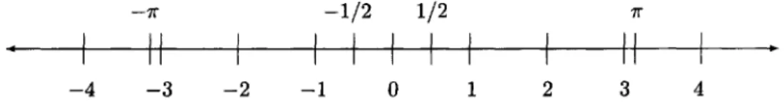
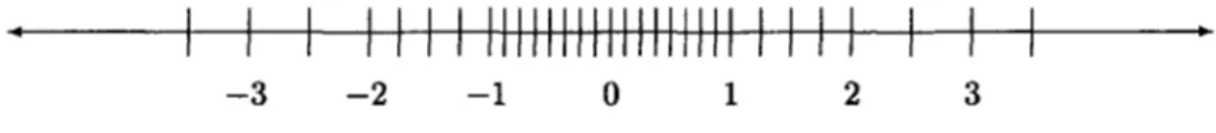
The real numbers can be represented conveniently by a line. Every point on the line corresponds to a real number, but only a few are marked in Figure 2.1. The line stretches infinitely far in both directions, towards oo and —oo, which are not themselves numbers in the conventional sense but are included among the extended real
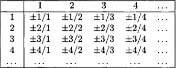
numbers. The integers are the numbers 0,1, —1,2, —2,3, —3, — We say that there is an infinite but countable number of integers; by this we mean that every integer would eventually appear in the list if we count for long enough, even though we can never count all of them. The rational numbers are those that consist of a ratio of two integers, e.g., 1/2, 2/3, 6/3; some of these, e.g., 6/3, are integers. To see that the number of rational numbers is countable, imagine them listed in an infinite two-dimensional array as in Figure 2.2. Listing the first line and then the second, and so on, does not work, since the first line never terminates. Instead, we generate a list of all rational numbers diagonal by diagonal: first 0, then ±1/1; then ±2/1, ±1/2; then ±3/1, ±2/2, ±1/3; then ±4/1, ±3/2, ±2/3, ±1/4; etc. In this way, every rational number (including every integer) is eventually generated. In fact, every rational number is generated many times (e.g., 1/2 and 2/4 are the same number). However, every rational number does have a unique representation in lowest terms, achieved by canceling any common factor in the numerator and denominator (thus 2/4 reduces to 1/2).
The irrational numbers are the real numbers that are not rational. Familiar exam-ples of irrational numbers are V% TT, and e. The numbers \/2 and TT have been studied for more than two thousand years. The number e, mentioned in the quote from HAL on page xiii, is the limit of
Figure 2.1: The Real Line
5
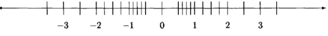
Figure 2.2: The Nonzero Rational Numbers
but there is no way of listing all the irrational numbers—the set of irrational numbers is said to be uncountable.
Positional Number Systems
The idea of representing numbers using powers of 10 was used by many ancient peoples, e.g., the Hebrews, the Greeks, the Romans, and the Chinese, but the positional system we use today was not. The Romans used a system where each power of 10 required a different symbol: X for 10, C for 100 = 102, M for 1000 = 103, etc., and repetition, together with additional symbols for quinary groupings, was used to indicate how many of each power of 10 were present. For example, MDCCCCLXXXV means 1000 + 500 + 400 + 50 + 30 + 5 = 1985. The familiar abbreviations such as IV for 4 were not used by the Romans. The Chinese system, which is still in use, is similar except that instead of repetition, symbols for the numbers 1 through 9 are used to modify each power of 10. These systems allowed easy transcription of numbers to an abacus for calculation, although they are not convenient for calculation with pencil and paper.
Large numbers cannot be conveniently represented by such systems. The positional notation used worldwide today requires a key idea: the representation of zero by a symbol. As far as we know, this was first used by the Babylonians about 300 B.C. Our decimal positional system was developed in India around 600 A.D. and was used for centuries by the Arabs in the Middle East before being passed on to Europe during the period 1200-1600—hence the name "Arabic numerals." This decimal, or base 10, system requires 10 symbols, representing the numbers 0 through 9. The system is called positional (or place-value) because the meaning of the number is understood from the position of the symbols, or digits, of the number. Zero is needed, for example, to distinguish 601 from 61. The reason for the decimal choice is the simple biological fact that humans have 10 fingers and thumbs. Indeed, the word digit derives from the Latin word for finger. Other positional systems developed by ancient peoples include the base 60 system used by the Babylonians, the vestiges of which are still seen today in our division of the hour into 60 minutes and the minute into 60 seconds, and the base 20 system developed by the Mayans, which was used for astronomical calculations. The Mayans are the only people known to have invented the positional number system, with its crucial use of a symbol for zero, independently of the Babylonians.
Decimal notation was initially used only for integers and was not used much for fractions until the 17th century. A reluctance to use decimal fractions is still evident in the use of quarters, eighths, sixteenths, etc., for machine tool sizes in the United States (and, until recently, for stock market prices).
CHAPTER 2. THE REAL NUMBERS 7
bit corresponds to a different power of 2, just as each digit of a decimal number corresponds to a different power of 10. Computer storage devices are all based on binary representation: the basic unit is also called a bit, which may be viewed as a single physical entity that is either "off' or "on." Bits in computer storage are organized in groups of 8, each called a byte. A byte can represent any of 256 = 28 (2 to the power 8) different bitstrings, which may be viewed as representing the integers from 0 to 255. Alternatively, we may think of these 256 different bitstrings as representing 256 different characters.4 A word is 4 consecutive bytes of computer storage (i.e., 32 bits), and a double word is 8 consecutive bytes (64 bits). A kilobyte is 1024 = 210 bytes, a megabyte is 1024 kilobytes (220 bytes), a gigabyte is 1024 megabytes (230 bytes), a terabyte is 1024 gigabytes (240 bytes), and a petabyte is 1024 terabytes (250 bytes). Petabyte storage devices now exist, although they would have seemed almost unimaginably large just a decade ago. It is often useful to remember that 210 is approximately 103. The Greek prefixes kilo, mega, giga, tera, and peta generally mean 103,106,109,1012, and 1015, respectively, in other scientific contexts, but with computers, powers of 2 are more important than powers of 10.
Although the binary system was not in wide use before the computer age, the idea of representing numbers as sums of powers of 2 is far from new. It was used as the basis for a multiplication algorithm described in the Rhind Mathematical Papyrus
[Cha79], written nearly four millennia ago (see p. xiii).
Binary and Decimal Representation
Every real number has a decimal representation and a binary representation (and, indeed, a representation in a base equal to any integer greater than 1). Instead of representation, we sometimes use the word expansion. The representation of integers is straightforward, requiring an expansion in nonnegative powers of the base. For example, consider the number
and its binary equivalent
Nonintegral real numbers have digits (or bits) to the right of the decimal (or binary) point; these expansions may be finite or nonterminating. For example, 11/2 has the expansions
and
Both of these expansions terminate. However, the number 1/10, which obviously has
4
the finite decimal representation (0.l)io, does not have a finite binary representation. Instead, it has the nonterminating expansion
Note that this representation, although nonterminating, is repeating. The fraction 1/3 has nonterminating expansions in both binary and decimal:
Rational numbers always have either finite or repeating expansions. For example,
In fact, any finite expansion can also be expressed as a repeating expansion. For example, 1/10 can be expressed as
However, we will use the finite expansion when it exists.
Irrational numbers always have nonterminating, nonrepeating expansions. For example,
The first 10 digits of e may suggest that its representation is repeating, but it is not.
Exercise 2.1 Conversion of integers from binary representation to decimal is straight-forward, because we are so familiar with the decimal representations of the powers of 2. Devise (or recall) a systematic method to convert the decimal representation of an in-teger to binary. Which do you find more convenient: determining the bits from left to right, or from right to left? Both methods are acceptable, but once you get the idea, one of them is easier to use systematically than the other. Test your choice on some examples and convert the binary results back to decimal as a check. Does your method extend to convert a finite decimal representation of a nonintegral rational number, such as 0.1, to its binary representation?
Chapter 3
Computer Representation of
Numbers
What is the best way to represent numbers on the computer? Let us start by con-sidering integers. Typically, integers are stored using a 32-bit word, so we confine our attention to this case. If we were concerned only with nonnegative integers, the representation would be easy: a bitstring specifying the binary representation of the integer. For example, the integer 71 (see (2.1)) would be stored as
The nonnegative integers that we can represent in this way range from 0 (a bitstring of 32 zeros) to 232 — 1 (a bitstring of 32 ones). The number 232 is too big, since its binary representation consists of a one followed by 32 zeros.
Signed Integers via 2's Complement
In fact, we need to be able to represent negative integers in addition to positive integers and 0. The most obvious idea is sign-and-modulus: use one of the 32 bits to represent the sign, and use the remaining 31 bits to store the magnitude of the integer, which may then range from 0 to 231 — 1. However, nearly all machines use a more clever representation called 2's complement.5 A nonnegative integer x, where 0 < x < 231 — 1, is stored as the binary representation of x, but a negative integer —y, where 1 < y < 231, is stored as the binary representation of the positive integer
For example, the integer —71 is stored as
In order to see that this is correct, let us add the 2's complement representations for 71 and -71 together:
5
There is a third system called 1's complement, where a negative integer — y is stored as the binary representation of 232 — y — 1. This system was used by some supercomputers in the 1960s and 1970s
but is now obsolete.
Adding in binary by hand is like adding in decimal. Proceed bitwise right to left; when 1 and 1 are added together, the result is 10 (base 2), so the resulting bit is set to 0 and the 1 is carried over to the next bit to the left. The sum of the representations for 71 and for —71 is thus the bitstring for 232, as required by the definition (3.1). The bit in the leftmost position of the sum cannot be stored in the 32-bit word and is called an overflow bit. If it is discarded, the result is 0—exactly what we want for the result of 71 -f (—71). This is the motivation for the 2's complement representation.
Exercise 3.1 Using a 32-bit word, how many different integers can be represented by
(a) sign and modulus; (b) 2 '5 complement? Express the answer using powers of 2. For which of these two systems is the representation for zero unique ?
Exercise 3.2 Suppose we wish to store integers using only a IQ-bit half-word (2 bytes). This is called a short integer format. What is the range of integers that can be stored using 2's complement? Express the answer using powers of 2 and also translate the numbers into decimal notation.
Exercise 3.3 Using an 8-bit format for simplicity, give the 2 's complement repre-sentation for the following integers: I, 10, 100, —1, —10, and —100. Verify that addition of a negative number to its positive counterpart yields zero, as required, when the overflow bit is discarded.
Exercise 3.4 Show that if an integer x between —231 and 231 — 1 is represented using 2 's complement in a 32-bit word, the leftmost bit is 1 if x is negative and 0 if x is positive or 0.
Exercise 3.5 An easy way to convert the representation of a nonnegative integer x to the 2's complement representation for —x begins by changing all 0 bits to Is and all 1 bits to Os. One more step is necessary to complete the process; what is it, and why?
All computers provide hardware instructions for adding integers. If two positive integers are added together, the result may give an integer greater than or equal to 231. In this case, we say that integer overflow occurs. One would hope that this leads to an informative error message for the user, but whether or not this happens depends on the programming language and compiler being used. In some cases, the overflow bits may be discarded and the programmer must be alert to prevent this from happening.6 The same problem may occur if two negative integers are added together, giving a negative integer with magnitude greater than 231.
On the other hand, if two integers with opposite sign are added together, integer overflow cannot occur, although an overflow bit may arise when the 2's complement bitstrings are added together. Consider the operation
where
Clearly, it is possible to store the desired result x — y without integer overflow. The result may be positive, negative, or zero, depending on whether x > y, x = y, or
x < y. Now let us see what happens if we add the 2's complement representations for
6The IEEE floating point standard, to be introduced in the next chapter, says nothing about
CHAPTER 3. COMPUTER REPRESENTATION OF NUMBERS 11
x and —y, i.e., the bitstrings for the nonnegative numbers x and 232 — y. We obtain the bitstring for
If x > y, the leftmost bit of the result is an overflow bit, corresponding to the power 232, but this bit can be discarded, giving the correct result x — y. If x < y, the result fits in 32 bits with no overflow bit, and we have the desired result, since it represents the negative value — (y — x) in 2's complement.
This demonstrates an important property of 2's complement representation: no special hardware is needed for integer subtraction. The addition hardware can be used once the negative number —y has been represented using 2's complement.
Exercise 3.6 Show the details for the integer sums 50 + (—100), 100 + (—50), and
50 + 50, using an 8-bit format.
Besides addition, the other standard hardware operations on integer operands are multiplication and division, where by the latter, we mean integer division, yielding an integer quotient. Multiplication may give integer overflow. Integer division by zero normally leads to program termination and an error message for the user.
Exercise 3.7 (D. Goldberg) Besides division by zero, is there any other division op-eration that could result in integer overflow?
Fixed Point
Now let us turn to the representation of nonintegral real numbers. Rational numbers could be represented by pairs of integers, the numerator and denominator. This has the advantage of accuracy but the disadvantage of being very inconvenient for arithmetic. Systems that represent rational numbers in this way are said to be symbolic rather than numeric. However, for most numerical computing purposes, real numbers, whether rational or irrational, are approximately stored using the binary representation of the number. There are two possible methods, called fixed point and floating point.
In fixed point representation, the computer word may be viewed as divided into three fields: one 1-bit field for the sign of the number, one field of bits for the binary representation of the number before the binary point, and one field of bits for the binary representation after the binary point. For example, in a 32-bit word with field widths of 15 and 16, respectively, the number 11/2 (see (2.2)) would be stored as
while the number 1/10 would be approximately stored as
The fixed point system is severely limited by the size of the numbers it can store. In the example just given, only numbers ranging in size from (exactly) 2~16 to (slightly less than) 215 could be stored. This is not adequate for many applications. Therefore, fixed point representation is rarely used for numerical computing.
Floating Point
and E is an integer. The numbers 5 and E are called the significant and the exponent,
respectively. For example, the exponential representation of 365.25 is 3.6525 x 10², and the exponential representation of 0.00036525 is 3.6525 x 10~4. It is always pos-sible to satisfy the requirement that 1 < S < 10, as S can be obtained from x by repeatedly multiplying or dividing by 10, decrementing or incrementing the exponent
E accordingly. We can imagine that the decimal point floats to the position immedi-ately after the first nonzero digit in the decimal expansion of the number—hence the name floating point.
For representation on the computer, we prefer base 2 to base 10, so we write a nonzero number x in the form
Consequently, the binary expansion of the significand is
For example, the number 11/2 is expressed as
Now it is the binary point that floats to the position after the first nonzero bit in the binary expansion of x, changing the exponent E accordingly. Of course, this is not possible if the number x is zero, but at present we are considering only the nonzero case. Since 60 is 1? we may write
The bits following the binary point are called the fractional part of the significand. We say that (3.2), (3.3) is the normalized representation of x, and the process of obtaining it is called normalization.
To store normalized numbers, we divide the computer word into three fields to represent the sign, the exponent E, and the significand 5, respectively. A 32-bit word could be divided into fields as follows: 1 bit for the sign, 8 bits for the exponent, and 23 bits for the significand. The sign bit is 0 for positive numbers and 1 for negative numbers. Since the exponent field is 8 bits, it can be used to represent exponents E
between —128 and 127 (for example, using 2's complement, though this is not the way it is normally done). The 23 significand bits can be used to store the first 23 bits after the binary point in the binary expansion of 5, namely, 61,..., 623- It is not necessary to store bo> since we know it has the value 1: we say that b0 is a hidden bit. Of course, it might not be possible to store the number x with such a scheme, either because E is outside the permissible range —128 to 127 or because the bits 624,625, • • • in the binary expansion of S are not all zero. A real number is called a floating point number if it can be stored exactly on the computer using the given floating point representation scheme. If a number x is not a floating point number, it must be rounded before it can be stored on the computer. This will be discussed later.
Using this idea, the number 11/2 would be stored as
and the number
7
CHAPTER 3. COMPUTER REPRESENTATION OF NUMBERS 13 would be stored as
To avoid confusion, the bits in the exponent field are not shown explicitly, for the moment, but written in the functional form "ebits(E)". Since the bitstring stored in the significand field is actually the fractional part of the significand, we also refer to this field as the fraction field. Given a string of bits in the fraction field, it is necessary to imagine that the symbols "1." appear in front of the string, even though these symbols are not stored.
In this scheme, if x is exactly a power of 2, so that the significand is the number 1.0, the bits stored in the fraction field are all 0 (since 60 is not stored). For example,
would be stored as
and the number would be stored as
Now consider the much larger number
This integer is much too large to store in a 32-bit word using the integer format discussed earlier. However, there is no difficulty representing it in floating point, using the representation
Exercise 3.8 What is the largest floating point number in this system, assuming the significand field can store only the bits 61... 623 and the exponent is limited by —128 <
E < 127? Don't forget that the hidden bit, bo, is 1.
Exercise 3.9 What is the smallest positive floating point number in this system? Remember the requirement that the number is normalized, i.e., that the hidden bit, bo, is 1.
Exercise 3.10 What is the smallest positive integer that is not exactly representable as a floating point number in this system?
Exercise 3.11 Suppose we change (3.2) so that the bounds on the significand are ½ < S < I, change (3.3) to
If a number x does not have a finite binary expansion, we must terminate its expansion somewhere. For example, consider the number
If we truncate this to 23 bits after the binary point, we obtain
However, if we then normalize this to obtain
so that there is a 1 before the binary point, we find that we now have only 19 correct bits after the binary point. This leads to the unnecessarily inaccurate representation
having 4 incorrect bits at the end of the significand. Clearly, this is not a good idea. It is preferable to first normalize and then truncate, so that we retain 23 correct bits after the binary point:
This way all the available bits are used. The alert reader will note that it might be better to round the final bit up to 1. We will discuss this later.
Precision, Machine Epsilon, and Ulp
The precision of the floating point system is the number of bits in the significand (including the hidden bit). We denote the precision by p. In the system just described,
p = 24 (23 stored bits in the fractional part of the significand and 1 leading hidden bit). Any normalized floating point number with precision p can be expressed as
The smallest such x that is greater than 1 is
We give a special name, machine epsilon,8 to the gap between this number and the number 1, and we write this as
More generally, for a floating point number x given by (3.4) we define
Ulp is short for unit in the last place. If x > 0, then ulp(x) is the gap between x and the next larger floating point number. If x < 0, ulp(x) is the gap between x and the next smaller floating point number (larger in absolute value).
Exercise 3.12 Let the precision p = 24, so e = 2~23. Determine ulp(x) for x having the following values: 0.25, 2, 3, 4, 10, 100, 1030. Give your answer as a power of 2;
do not convert this to decimal.
8 Many authors define machine epsilon to be half the gap. We follow [Hig96] in our definitions of
CHAPTER 3. COMPUTER REPRESENTATION OF NUMBERS 15
The Special Number Zero
So far, we have discussed only nonzero numbers. The number zero is special. It cannot be normalized, since all the bits in its representation are zero. Thus, it cannot be represented using the scheme described so far. A pattern of all zeros in the significand represents the significand 1.0, not 0.0, since the bit 60 is hidden. There are two ways to address this difficulty. The first, which was used by most floating point implementations until about 1975, is to give up the idea of a hidden bit and instead insist that the leading bit 60 in the binary representation of a nonzero number must be stored explicitly, even though it is always 1. In this way, the number zero can be represented by a significand that has all zero bits. This approach effectively reduces the precision of the system by one bit, because, to make room for 60> we must give up storing the final bit (623 in the system described above). The second approach is to use a special string in the exponent field to signal that the number is zero. This reduces by one the number of possible exponents E that are allowed for representing nonzero numbers. This is the approach taken by the IEEE standard, to be discussed in the next chapter. In either case, there is the question of what to do about the sign of zero. Traditionally, this was ignored, but we shall see a different approach in the next chapter.
The Toy Number System
It is quite instructive to suppose that the computer word size is much smaller than 32 bits and work out in detail what all the possible floating point numbers are in such a case. Suppose that all numbers have the form
with 60 stored explicitly and all nonzero numbers required to be normalized. Thus, 60 is allowed to be zero only if 61 and 62 are also zero, indicating that the number represented is zero. Suppose also that the only possible values for the exponent E are — 1,0, and 1. We shall call this system the toy floating point number system. The set of toy floating point numbers is shown in Figure 3.1.
Figure 3.1: The Toy Floating Point Numbers
The precision of the toy system is p = 3. The largest number is (1.11)2 x 21 = (3.5)io, and the smallest positive number is (1.00)2 x 2"1 = (0.5)io- Since the next floating point number bigger than 1 is 1.25, machine epsilon for the toy system is
twice as big, i.e., ulp(x) = 2e, and for those x with E — — 1, the gap is ulp(x) = ^e.
Summarizing, the gap between a positive toy floating point number x — (b0-b1b2)2 x2£ and the next bigger toy floating point number is
as already noted in (3.6).
Another important observation to make about Figure 3.1 is that the gaps between zero and ±0.5 are much greater than the gaps between numbers ranging from ±0.5 to ±1. We shall show in the next chapter how these gaps can be filled in with the introduction of subnormal numbers.
Exercise 3.13 Suppose we add another bit to the toy number system, allowing signif-icands of the form 60-616263, with 60 stored explicitly as before and all nonzero numbers required to be normalized. The restrictions on the exponent are unchanged. Mark the new numbers on a copy of Figure 3.1.
Fixed Point versus Floating Point
Some of the early computers used fixed point representation and some used floating point. Von Neumann was initially skeptical of floating point and promoted the use of fixed point representation. He was well aware that the range limitations of fixed point would be too severe to be practical, but he believed that the necessary scaling by a power of 2 should be done by the programmer, not the machine; he argued that bits were too precious to be wasted on storing an exponent when they could be used to extend the precision of the significand. Wilkinson experimented extensively with a compromise system called block floating point, where an automatic scale factor is maintained for a vector, i.e., for a block of many numbers, instead of one scale factor per number. This means that only the largest number (in absolute value) in the vector is sure to be normalized; if a vector contains numbers with widely varying magnitudes, those with smaller magnitudes are stored much less accurately. By the late 1950s it was apparent that the floating point system is far more versatile and efficient than fixed point or block floating point.
Chapter 4
IEEE Floating Point
Representation
Floating point computation was in standard use by the mid 1950s. During the sub-sequent two decades, each computer manufacturer developed its own floating point system, leading to much inconsistency in how one program might behave on different machines. For example, although most machines developed during this period used binary floating point systems roughly similar to the one described in the previous chapter, the IBM 360/370 series, which dominated computing during the 1960s and 1970s, used a hexadecimal system (base 16). On these machines, the significand is stored using 24 bits, to be interpreted as 6 hexadecimal digits, leaving 1 bit for the sign and 7 bits for the exponent (representing a power of 16). Normalization requires only that the first hexadecimal digit be nonzero; consequently, the significand could have up to 3 leading zero bits. Therefore, the accuracy of the significands ranges from 21 to 24 bits; some numbers (such as 1/10; see (2.3)) are represented less accurately than on a binary machine. One motivation for this design was to reduce the bit shift-ing required durshift-ing floatshift-ing point add and subtract operations. Another benefit is that the hexadecimal base allows a much greater range of normalized floating point numbers than a binary system permits.
In addition to inconsistencies of representation, there were also many inconsis-tencies in the properties of floating point arithmetic. See Chapter 6 for examples of difficulties that could arise unexpectedly on some machines. Consequently, it was very difficult to write portable software that would work properly on all machines. Programmers needed to be aware of various difficulties that might arise on different machines and attempt to forestall them.
A Historic Collaboration: IEEE p754
In an extraordinary cooperation between academic computer scientists and micropro-cessor chip designers, a standard for binary floating point representation and arith-metic was developed in the late 1970s and early 1980s and, most importantly, was followed carefully by the microprocessor industry. As this was the beginning of the personal computer revolution, the impact was enormous. The group of scientists who wrote the standard did so under the auspices of the Institute for Electrical and Electronics Engineers;8 the group was known as IEEE p754. The academic com-puter scientists on the committee were led by William Kahan of the University of
8
California at Berkeley; industrial participants included representatives from Apple, Digital Equipment Corporation (DEC), Intel, Hewlett-Packard, Motorola, and Na-tional Semiconductor. Kahan's interest in the project had been sparked originally by the efforts of John Palmer, of Intel, to ensure that Intel's new 8087 chip would have the best possible floating point arithmetic. An early document that included many of the ideas adopted by the standard was written in 1979 by Kahan, Coonen, and Stone; see [Cod8l]. Kahan was awarded the 1989 Turing Prize by the Association of Computing Machinery for his work in leading IEEE p754.
In [Sev98], Kahan recalled: "It was remarkable that so many hardware people there, knowing how difficult p754 would be, agreed that it should benefit the commu-nity at large. If it encouraged the production of floating-point software and eased the development of reliable software, it would help create a larger market for everyone's hardware. This degree of altruism was so astonishing that MATLAB's creator Cleve Moler used to advise foreign visitors not to miss the country's two most awesome spectacles: the Grand Canyon, and meetings of IEEE p754."
The IEEE standard for binary floating point arithmetic was published in 1985, when it became known officially as ANSI/IEEE Std 754-1985 [IEE85]. In 1989, it received international endorsement as IEC 559, later designated IEC 60559. A sec-ond IEEE floating point standard, for radix-independent floating point arithmetic, ANSI/IEEE Std 854-1987 [IEE87], was adopted in 1987. The second standard was motivated by the existence of decimal, rather than binary, floating point machines, particularly hand-held calculators, and set requirements for both binary and decimal floating point arithmetic in a common framework. The demands for binary arithmetic imposed by IEEE 854 are consistent with those previously established by IEEE 754. In this book, when we write "the IEEE standard," we refer to the binary standard, IEEE 754. The term "IEEE arithmetic" is used to mean floating point arithmetic that is in compliance with the IEEE standard. For more on the development of the stan-dard, see [CodSl] and [PH97, Section 4.12]. At the time of this writing, the standard is being considered for revision [IEE-R].
IEEE Floating Point Essentials
The IEEE standard has three very important requirements:
• consistent representation of floating point numbers by all machines adopting the standard (discussed in this chapter);
• correctly rounded floating point operations, using various rounding modes (see Chapters 5 and 6);
• consistent treatment of exceptional situations such as division by zero (see
Chap-ter 7).
CHAPTER 4. IEEE FLOATING POINT REPRESENTATION 19
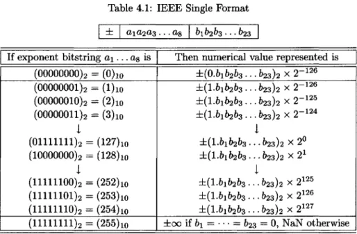
Table 4.1: IEEE Single Format
now that —0 and 0 are two different representations for the same number zero, while —oo and oo represent two very different numbers. Another special number is NaN, which stands for "Not a Number" and is accordingly not a number at all, but an error pattern. This too will be discussed later. All of these special numbers, as well as others called subnormal numbers, are represented through the use of a specific bit pattern in the exponent field.
The Single Format
The IEEE standard specifies two basic representation formats, single and double. Single format numbers use a 32-bit word and their representations are summarized in Table 4.1.
Let us discuss Table 4.1 in some detail. The ± refers to the sign of the number, a zero bit being used to represent a positive sign. The first line shows that the representation for zero requires a special zero bitstring for the exponent field as well as a zero bitstring for the fraction field, i.e.,
No other line in the table can be used to represent the number zero, for all lines except the first and the last represent normalized numbers, with an initial bit equal to 1; this is the one that is hidden. In the case of the first line of the table, the hidden bit is 0, not 1. The 2~126 in the first line is confusing at first sight, but let us ignore that for the moment since (0.000... 0)2 x 2~126 is certainly one way to write the number 0. In the case when the exponent field has a zero bitstring but the fraction field has a nonzero bitstring, the number represented is said to be subnormal.9 Let us postpone the discussion of subnormal numbers for the moment and go on to the other lines of the table.
All the lines of Table 4.1 except the first and the last refer to the normalized numbers, i.e., all the floating point numbers that are not special in some way. Note
9
especially the relationship between the exponent bitstring a1a2a3 • • • a8 and the actual exponent E. We see that the exponent representation does not use either the sign-and-modulus or the 2's complement integer representation discussed in the previous chapter, but something called biased representation; the bitstring that is stored is the binary representation of E + 127. The number 127, which is added to the desired exponent E, is called the exponent bias. For example, the number 1 = (1.000... 0)2 x 2° is stored as
Here the exponent bitstring is the binary representation for 0 + 127 and the fraction bitstring is the binary representation for 0 (the fractional part of 1.0). The number 11/2 = (1.011)2 x 22 is stored as
The number 1/10 = (1.100110011.. .)z x 2 4 has a nonterminating binary expansion. If we truncate this to fit the significand field size, we find that 1/10 is stored as
We shall see other rounding options in the next chapter.
The range of exponent field bitstrings for normalized numbers is 00000001 to 11111110 (the decimal numbers 1 through 254), representing actual exponents from -E'min = —126 to .Emax = 127. The smallest positive normalized number that can be stored is represented by
and we denote this by
The largest normalized number (equivalently, the largest finite number) is represented
by
and we denote this by
The last line of Table 4.1 shows that an exponent bitstring consisting of all 1s is a special pattern used to represent ±00 or NaN, depending on the fraction bitstring. We will discuss these in Chapter 7.
Subnormals
Finally, let us return to the first line of the table. The idea here is as follows: although 2~126 is the smallest normalized number that can be represented, we can use the combination of the special zero exponent bitstring and a nonzero fraction bitstring to represent smaller numbers called subnormal numbers. For example, 2~127, which is the same as (0.1)2 x 2~126, is represented as
while 2~149 = (0.0000... 01)2 x 2~ 126
CHAPTER^ IEEE FLOATING POINT REPRESENTATION 21
Figure 4.1: The Toy System Including Subnormal Numbers
This is the smallest positive number that can be stored. Now we see the reason for the 2-126 in the first line. It allows us to represent numbers in the range immediately below the smallest positive normalized number. Subnormal numbers cannot be normalized, since normalization would result in an exponent that does not fit in the field.
Let us return to our example of the toy system with a tiny word size, illustrated in Figure 3.1, and see how the addition of subnormal numbers changes it. We get six extra numbers: ±(0.11)2x2~
1
= 3/8, ±(0.10)2 x2-1
= 1/4, and ±(0.01)2 x2-1
= 1/8; these are shown in Figure 4.1. Note that the gaps between zero and ±0.5 are evenly filled in by the subnormal numbers, using the same spacing as that between the numbers in the range ±0.5 to ±1.
Subnormal numbers are have less room for nonzero bits in the fraction field than normalized numbers. Consequently, the accuracy to which they can approximate a number drops as the size of the subnormal number decreases. Thus (1/10) x 2~123 = (0.11001100.. .)2 x 2~126 is truncated to
while (1/10) x 2~135 = (0.11001100.. .)2 x 2~138 is truncated to
Exercise 4.1 Determine the IEEE single format floating point representation for the following numbers: 2, 30, 31, 32, 33, 23/4, (23/4) x 2100, (23/4) x 2-100, and (23/4) x 2~135. Truncating the significand as in the 1/10 example, do the same for the numbers
1/5 = (1/10) x 2, 1024/5 = (1/10) x 211, and (1/10) x 2~140, using (2.3) to avoid decimal-to-binary conversions.
Exercise 4.2 What is the gap between 2 and the first IEEE single format number larger than 2 ? What is the gap between 1024 and the first IEEE single format number larger than 1024?
Exercise 4.3 Give an algorithm that, given two IEEE single format floating point numbers x and y, determines whether x is less than, equal to, or greater than y, by comparing their representations bitwise from left to right, stopping as soon as the first differing bit is encountered. Assume that neither x nory is ±0, ±00 , or NaN. The fact that such a comparison can be done easily motivates biased exponent representation. It also justifies referring to the left end of the representation as the "most significant" end.
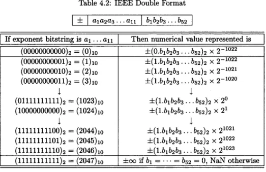
Table 4.2: IEEE Double Format
Table 4.3: Range of IEEE Floating Point Formats
The Double Format
The single format is not adequate for many applications, either because higher preci-sion is desired or (less often) because a greater exponent range is needed. The IEEE standard specifies a second basic format, double, which uses a 64-bit double word. Details are shown in Table 4.2. The ideas are the same as before; only the field widths and exponent bias are different. Now the exponents range from Emin = —1022 to
•Emax = 1023, and the number of bits in the fraction field is 52. Numbers with no finite binary expansion, such as 1/10 or TT, are represented more accurately with the double format than they are with the single format. The smallest positive normalized double format number is
and the largest is
We summarize the bounds on the exponents and the values of the smallest and largest normalized numbers given in (4.1), (4.2), (4.3), and (4.4) in Table 4.3.
Single versus Double
CHAPTER 4. IEEE FLOATING POINT REPRESENTATION 23
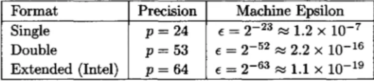
Table 4.4: Precision of IEEE Floating Point Formats
and we shall therefore assume that the double format is always provided. Support for the requirements may be provided by hardware or software, but almost all machines have hardware support for both the single and double formats. Because of its greater precision, the double format is preferred for most applications in scientific computing, though the single format provides an efficient way to store huge quantities of data.
The Extended Format
The standard also strongly recommends support for an extended format, with at least 15 bits available for the exponent and at least 63 bits for the fractional part of the significand. The Intel microprocessors implement arithmetic with the extended format in hardware, using 80-bit registers, with 1 bit for the sign, 15 bits for the exponent, and 64 bits for the significand. The leading bit of a normalized or subnormal number is not hidden as it is in the single and double formats, but is explicitly stored. Otherwise, the format is much the same as single and double. Other machines, such as the Spare microprocessor used in Sun workstations, implement extended precision arithmetic in software using 128 bits. Consequently, computations with the extended format are fast on an Intel microprocessor but relatively slow on a Spare.
Precision and Machine Epsilon of the IEEE Formats
Recall from the previous chapter that we use the notation p (precision) to denote the number of bits in the significand and e (machine epsilon) to mean the gap between 1 and the next larger floating point number. The precision of the IEEE single format is p = 24 (including the hidden bit); for the double format it is p = 53 (again, including the hidden bit). When we speak of single precision, we mean the precision of the IEEE single format (p = 24); likewise double precision means the precision of the IEEE double format (p = 53).10 The precision of the Intel extended format is
p = 64, since it has no hidden bit. The first single format number larger than 1 is 1 + 2~23, and the first double format number larger than 1 is 1 + 2~52. With the Intel extended format, since there is no hidden bit, 1 + 2~64 cannot be stored exactly; the first extended format number larger than 1 is 1 + 2~63. These observations are summarized in Table 4.4, showing the values of the precision p and machine epsilon e, together with its approximate decimal equivalent, for each of the single, double, and Intel extended formats.
Significant Digits
The single precision p = 24 corresponds to approximately 7 significant decimal digits,
since
10
Here « means approximately equals.11 Equivalently,
The double precision p = 53 corresponds to approximately 16 significant decimal digits,
and the Intel extended precision p = 64 corresponds to approximately 19 significant decimal digits. We deliberately use the word approximately here, because defining
significant digits is problematic. The IEEE single representation for
is, when converted to decimal,
To how many digits does this approximate TT? We might say 7, since the first 7 digits of both numbers are the same, or we might say 8, since if we round both numbers to 8 digits, rounding TT up and the approximation down, we get the same number 3.1415927. See [Hig96] for a discussion of the difficulties involved in using definitions like these to define "significant digits." We will see a better way to measure accurate digits in the next chapter.
Big and Little Endian
Modern computers address memory by bytes. A 32-bit word consists of 4 consecutive bytes with addresses, say, B\,..., .B4, where B4 = B1 + 3. Suppose we store a single format floating point number in this word. We know from Table 4.1 that a single format number has the bit format
where a is the sign bit. This corresponds to 4 bytes, of which the "most significant" (see Exercise 4.3) is the byte
Let us ask the question: is this most significant byte stored in byte B1 or byte B4!
Surprisingly, it turns out that the answer depends on the machine. Addressing systems for which the answer is B1 are called Big Endian (the first byte B\ stores the "big end" of the floating point word). Addressing systems for which the answer is B4 are called
Little Endian (the first byte B1 stores the "little end," i.e., the least significant byte, of the floating point word). Sun and IBM machines use Big Endian addressing, while Intel uses Little Endian addressing. Some microprocessors, such as the DEC Alpha, can operate in either mode. The fact that different machines use different schemes means that care must be taken when passing data from one machine to another. The addressing schemes were given the names Big and Little Endian by Danny Cohen, in a whimsical reference to Gulliver's Travels, where the issue is which end of a boiled egg should be opened [HP95, Chapter 3.4].
11
Chapter 5
Rounding
We saw in the previous chapter that the finite IEEE floating point numbers can all be expressed in the form
where p is the precision of the floating point system with, for normalized numbers, bo = 1 and Emin < E < Emax and, for subnormal numbers and zero, 60 = 0 and E =
£-min- We denoted the largest normalized number by Nmax and the smallest positive
normalized number by Nmin. There are also two infinite floating point numbers, ±00.
We now introduce a new definition. We say that a real number x is in the normal-ized range of the floating point system if
The numbers ±0 and ±00 and the subnormal numbers are not in the normalized range of the floating point system, although they are all valid floating point numbers.
Suppose that a real number x is not a floating point number. Then at least one (and perhaps both) of the following must be true:
• x is outside the normalized range (its absolute value is greater than Nmax or
less than -Nmin). For example, the numbers 2130 and 2~130 are both outside the
normalized range of the single format.
• The binary expansion of x requires more than p bits to specify the number exactly; equivalently, the floating point precision p is too small to represent x
exactly. For example, the number
requires more bits to specify it than are available in the significand field of the single format.
In either case, we need to approximate x by something else.
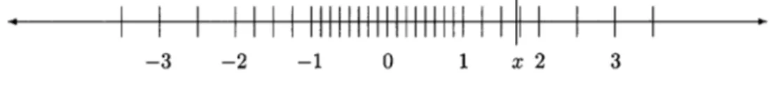
Let us define x- to be the floating point number closest to x that is less than or equal to x, and define x+ to be the floating point number closest to x that is greater than or equal to x. If the closest number is zero, we set the sign of zero to be the sign of x. For example, consider the toy floating point number system again. If x = 1.7, then x- = 1.5 and x+ = 1.75, as shown in Figure 5.1.
Returning to the IEEE floating point formats, let x be a positive number in the normalized range, and write x in the normalized form
Figure 5.1: Rounding in the Toy System
It follows that the closest floating point number less than or equal to x is
i.e., X- is obtained by truncating the binary expansion of the significand, discarding
bp, bp+i, etc. If x is not a floating point number, i.e., at least one of the discarded bits
in its expansion is nonzero, then
the next floating point number bigger than X-, and therefore also the next one that is bigger than x (which must lie between x~ and x+). Here the "1" in the increment is in the (p — l)th place after the binary point, so the gap between X- and x+ is
Note that this quantity is the same as ulp(x_), defined in (3.6). Finding the binary expansion of x+ is a little more complicated, since one bit must be added to the last
place of the fraction field of X-; this may involve some "carries" and possibly, if all the bits in the field are 1, an increment in the exponent field.
If x is greater than -/Vmax, then
If x is positive but less than Nmin, then X- is either subnormal or zero, and x+ is
either subnormal or Nm i n.
If x is negative, the situation just described is reversed. For example, if x is negative and in the normalized range, x+ is obtained by dropping bits bp, bp+i, etc.,
since discarding bits of a negative number makes the number closer to zero, and therefore larger (further to the right on the real line). If x is negative but its absolute value is less than Nm i n, then x+ is either a negative subnormal number or —0, and X- is either a negative subnormal number or —Nm i n.
Correctly Rounded Values
The IEEE standard defines the correctly rounded value of x, which we shall denote by round(x), as follows. If x is a floating point number, then round(x) = x. Otherwise, the correctly rounded value depends on which of the following four rounding modes is in effect:
• Round down (sometimes called round towards — oo). round(x;) = X-.
CHAPTER 5. ROUNDING 27 • Round towards zero.
round(x) = X- if x > 0; round(x) = x+ if x < 0. • Round to nearest.
round(x) is either x_ or x+, whichever is nearer to x (unless |x| > Nmax).
In case of a tie, the one with its least significant bit equal to zero is chosen. See below for details.
If x is positive, then X- is between zero and x, so round down and round towards zero have the same effect. If x is negative, then #+ is between zero and x;, so round up
and round towards zero have the same effect. In both cases, round towards zero simply requires truncating the binary expansion, unless x is outside the normalized range.
The rounding mode that is almost always used in practice is round to nearest. In the toy system, round to nearest gives round(l.7) = 1.75 (see Figure 5.1). Consider x
given by (5.1) again. If the first bit that cannot be stored, bpj is 0, round to nearest
rounds down to x_; on the other hand, if bp = 1 and at least one other subsequent nonzero bit is also 1, round to nearest rounds up to x+. If bp = 1 and all subsequent bits are 0, there is a tie. The least significant bits, i.e., the (p — l)th bits after the binary point, of X- and x+ must be different, and the one for which this bit equals 0 is chosen to break the tie. For the motivation for this rule, see [Gol9l, Theorem 5]. When the word round is used without any mention of a rounding mode, it almost always means round to nearest. The IEEE standard requires that the default rounding mode be round to nearest.
There is an exception to the round to nearest rule when x > Nmax. In this case, round(x) is defined to be Nmax if x < Nmax + urp(-/Vmax)/2 and oo otherwise. From
a strictly mathematical point of view, this is not consistent with the usual definition, since x cannot be said to be closer to oo than to ATmax. From a practical point of view,
however, the choice oo is important, since round to nearest is the default rounding mode and rounding to Nmax may give very misleading results. Similar considerations
apply when x < —Nmax.
Exercise 5.1 What are the IEEE single format binary representations for the rounded value of 1/10 (see (2.3),), using each of the four rounding modes? What are they for
1 + 2~25 and!130?
Exercise 5.2 Using the IEEE single format, construct an example where X- and
x+ are the same distance from x, and use the tie-breaking rule to define round(a;),
assuming the round-to-nearest mode is in effect.
Exercise 5.3 Suppose that 0 < x < Nm-m, but that x is not a subnormal floating point number. We can write
where at least one of bp,bp+i,..., is not zero. What is X-? Give some examples, assuming the single format is in use (p = 24, Emin = —126).
Absolute Rounding Error and Ulp
the absolute rounding error associated with x. Its value depends on the precision and rounding mode in effect. In toy precision, when round down or round towards zero is in effect, we have round(1.7) = 1.5, so
but if round up or round to nearest is in effect, we have round(1.7) = 1.75, so
Returning again to the IEEE formats, if x is in the normalized range, with
the absolute rounding error associated with x is less than the gap between X- and x+,
regardless of the rounding mode, and we have from (5.2) that
Informally, we say that the absolute rounding error is less than one w/p, meaning ulp(a:_) if x > 0 and ulp(x+) if x < 0. When round to nearest is in effect, we can say something stronger: the absolute rounding error is less than or equal to half the gap
between X- and x+, i.e.,
Informally, we say that the absolute rounding error is at most half an ulp. By defini-tion, the absolute rounding error is zero when x is a floating point number.
Exercise 5.4 What is abserr(l/10) using the IEEE single format, for each of the four rounding modes? (See Exercise 5.1.)
Exercise 5.5 Suppose that x > Nmax. What is abserr(a;)7 for each of the four round-ing modes? Look carefully at the definition of round (x}.
Exercise 5.6 What is abserr(ar) for x given in Exercise 5.3, using the rounding mode
round down ?
Exercise 5.7 Do the bounds (5.5) and (5.6) hold when \x\ < Nmin? Explain.
Relative Rounding Error, Machine Epsilon, Significant Digits
The relative rounding error associated with a nonzero number x is defined by
where
Assuming that £, given by (5.4), is in the normalized range and is not a floating point number, we have
CHAPTER 5. ROUNDING 29 using (5.5), (5.9), and the definition of e in (3.5). In the case of round to nearest, we have
using (5.6) and (5.9). The same inequalities hold when x is a floating point number in the normalized range, since then relerr(x) = abserr(x) = 0.
Exercise 5.8 Do the bounds (5.10) and (5.11) hold when \x\ < Nmin? Explain. (See Exercise 5.7.,)
It follows from (5.10) and (5.11) that
and, for round to nearest,
We can think of — Iog2 relerr(x) as measuring the number of bits to which round(x)
and x agree: at least p — 1, and at least p in the case of round to nearest. Likewise, it follows from (5.10) that
and we can think of — Iog10 relerr(a;) as measuring the number of decimal digits to
which round(x) and x agree. Consulting Table 4.4 for the value of e, we see that this means that round(x) and x agree to at least about 7 digits when IEEE single precision is in use, and to about 16 digits in the case of IEEE double.
It also follows from (5.8) that
Combining this with (5.10) and (5.11), we have completed the proof of the following result, which is so important that we state it as the only theorem in this book.
Theorem 5.1 Let x be any real number in the normalized range of a binary floating point system with precision p. Then
for some 6 satisfying
where e, machine epsilon, is the gap between 1 and the next larger floating point number, i.e.,
Furthermore, if the rounding mode in effect is round to nearest,
Theorem 5.1 is very important, because it shows that, no matter how x is stored or displayed, either in binary format or in a converted decimal format, we may think of its value not as exact but as exact within a factor of 1 + e. Thus, for example, IEEE single format numbers are accurate to within a factor of about 1 +10~7, which means that they have approximately seven significant decimal digits.
Exercise 5.9 Does the result established by Theorem 5.1 still hold if 0< \x\ < N m i n?