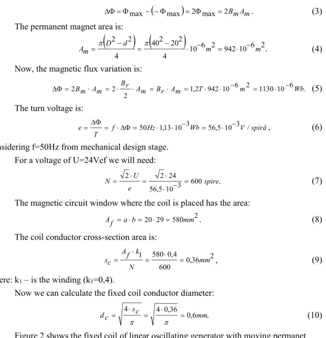
THE STUDY, DESIGN AND TESTING OF A LINEAR OSCILLATING
GENERATOR WITH MOVING PERMANENT MAGNETS
Teodora Susana OROS (POP)1, Ioan BERINDE1, Radu POP1
1 Technical University of Cluj Napoca
Keywords: linear oscillating generator, permanent magnet
Abstract: This paper presents a study, design and testing of a Linear Oscillating Generator. There are presented the main steps of the magnetic and electric calculations for a permanent magnet linear alternator of fixed coil and moving magnets type. Finally it has been shown the comparative analysis between the linear oscillating generator with moving permanent magnets in no load operation and load operation.
1. INTRODUCTION
A comprehensive presentation of the history, types and applications of linear electric actuators and generators was made by John Boldea in [1]. A new type of tubular linear permanent magnet generator for applications in convertorele wave energy was presented by Szabo et al. in. Note that applications of linear electric generators wave energy converters is restricted due to low frequency waves and large size of the resulting magnetic circuit at these frequencies.
Many more applications of permanent magnet generators are converters energy Stirling engines Piston free [2,3,4,5,6] .
eliminates conversion of linear motion into rotary motion Stirling engine (crank system);
structure is simpler;
higher efficiency, especially in the operation of the resonance spring system; simplicity conditioning system of electricity generated by single-phase operation. Oscillating linear generators can be classified into three main categories:
linear oscillating generator with moving coil;
linear oscillating generator with moving permanent magnets; linear oscillating generator with moving iron.
It will continue to study, design and test only of the linear oscillating generator with moving permanent magnets.
2. THE LINEAR OSCILLATING GENERATOR WITH MOVING PERMANENT MAGNETS
2.1. The design magnetic circuit of linear oscillating generator with moving permanent magnets
This alternator is of the synchronous type with excitation from the permanent magnets. From the figure 3 it can be seen that field line passes the air gap for two times, so the necessary magnetomotive force is:
A g
B mm
F 7 2 1 10 3 955
10 4 6 , 0 2 0
, (1)
where:
Bg – magnetic flux density (Bg=0,6 T);
δ – the air gap lenght (δ=1 mm);
μ0 – magnetic permeability of the air [H·m-1, N·A-2];
For the magnetization it was chosen two ring permanent magnets of the type EURONEOS 40x20x13.3, which have the properties presented in the table 1.
Table 1. The permanent magnets properties of the type EURONEO 3 40X20X13.3
Can be seen that 11,54 kA=11540 A>955 A, therefore, the magnets were chosen correctly.
2.2. The coil design of linear oscillating generator
The indus coil design will be made according to the voltage that is aimed to be induced in the coil. We considered an induced voltage at 10 Hz frecvency of U=18 Vef
voltage. The magnetic flux by this coil varies between + max and -max so that the magnetic
flux variations:
max
2 max 2BmAmmax
. (3)
The permanent magnet area is:
10 6 2 942 10 6 2. 4 2 20 2 40 4 2 2 m m d D mA (4)
Now, the magnetic flux variation is:
. 6 10 1130 2 6 10 942 2 , 1 2 2
2BmAm Br Am Br Am T m Wb
(5)
The turn voltage is:
spiră V Wb Hz f T
e 50 1,13103 56,5103 / , (6)
considering f=50Hz from mechanical design stage. For a voltage of U=24Vef we will need:
. 600 3 10 5 , 56 24 2 2 spire e U
N
(7)
The magnetic circuit window where the coil is placed has the area: 2 580 29 20 mm b a f
A . (8)
The coil conductor cross-section area is:
2 36 , 0 600 4 , 0 580 1 mm N k f A c
s , (9)
where: k1 – is the winding (k1=0,4).
Now we can calculate the fixed coil conductor diameter:
. 6 , 0 36 , 0 4 4 mm c s c
d
(10)
4 5 6 7
3
2
1
Fig. 3 Test bench of linear oscillating generator with moving permanent magnets: 1 – vibrometer, 2- autotransformer, 3 – ampermeter, 4 – vibration sensor, 5 – vibrator VEDP-10,
6 – linear oscillating generator with moving permanent magnets, 7 - oscilloscope Fluke 196.
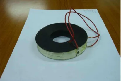
Fig. 2 The fixed coil of linear oscillating generator with moving permanent magnets
3. TESTING OF LINEAR OSCILLATING GENERATOR WITH MOVING PERMANENT MAGNETS
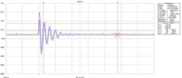
a signal damped voltage (see figure 4). This signal was viewed with Fluke 196 digital oscilloscope.
Fig. 4 Free oscillations of linear generator with moving permanent magnets
In this figure can see that the distnace in time between two peaks of oscillation is 18 ms, which corresponds to the frequency of 55,5 Hz, similar to taken as a given design (50 Hz).
3.2. The testing of linear oscillating generator with moving permanent magnets driven by vibrator VEDP-10
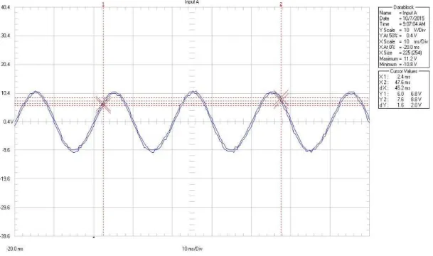
Figure 5 shows the answer of linear oscillating generator with moving permanent magnets driven by vibrator VEDP-10 in load operation with a frequency 50 Hz and vibration amplitude A=3 mm. This answer has been counted by the Fluke 196 oscilloscope.
So, we can see that generated alternating voltage amplitude is 122 V respectively 86 Vef. This high value, is much higher than the amount considered design (24 Vef). This thing is
due to the large number of turns of the coil fised and because the two permanent magnets of moving equipment, which it was of very good quality and functioning almost resonance oscillating system.
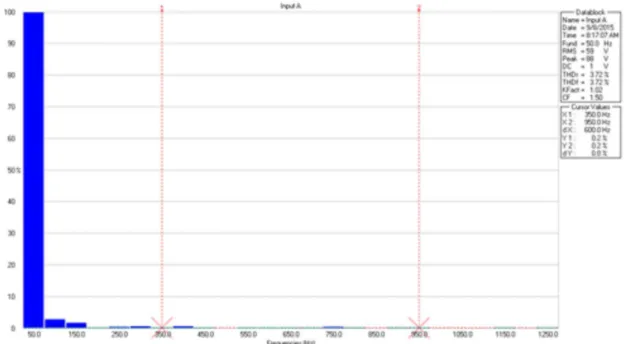
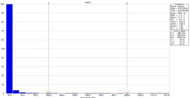
Also, with Fluke 196 digital oscilloscope an analysis was made sinusoidal harmonic voltage generated by the linear oscillating generator with moving permanent magnets and the results is shown in figure 6.
Fig. 6 Harmonic analysis of voltage generated by linear oscillating generator with moving permanent magnets
We can see that the voltage generated has a important harmonic of second snd third order, and the THD is 3,72%, which confirms the finding visual on voltage generated.
3.3. The testing of linear oscillating generator with moving permanent magnets driven by vibrator VEDP-10 in load operation
Figure 7 shows the test bench of linear oscillating generator in load operation with moving permanent magnets.
Fig. 8 The test of linear oscillating generatorwith on a load resistance Rs=50 Ω
Figure 9 shows the spectral analysis of voltagew generated by the linear oscillating generator with moving permanent magnets in load operation.
7 6 5 4 3 1 2
Fig. 7 Test bench of linear oscilating generator in load operation:
1 – vibrometer, 2- autotransformer, 3 – ampermeter, 4 – vibrator VEDP-10, 5 – linear oscillating generator with permanent magnets; 6 –ampermeter of load, 7 –voltmeter of load, 8 – load Rs=50 Ω;
9 - oscilloscope Fluke 196. 8
Fig. 9 Spectral analysis of voltage generated by the linear oscillating generator in load
Se observă că sarcina funcționează ca un filtru de armonici, deoarece coeficientul de distorsiune THD s-a redus de la 3,72% în gol la 3,63% în sarcină.
3.4 Measuring magnetic induction in the air gap of the linear oscillating generator
It was used for measuring a teslametru with Hall probe, which probe has been inserted ito the gap through the recesses of the membrane spring ina position pressed by 5 mm of the mobile equipment. The measured value was 0,57 T very close value of the design data 0,6 T and the magnetic field calculated by method analytical of reluctance (0,57,T) and the finite element method.
4. COMPARATIVE ANALYSIS OF A LINEAR OSCILLATING GENERATOR WITH MOVING PERMANENT MAGNETS IN NO LOAD AND IN LOAD
OPERATION
The cogging force present, which on the vibration amplitude small (2 mm) much smaller than the polar pich (14 mm) increases the strength of the excitation vibrators;
Wave voltage has not a sinusoidal waveform THD=3.72% pure,
In terms of technology requires permanent magnets easier and cheaper;
explained by the fact that the amplitude of vibration (2 mm) was less than 5 mm nominal amplitude;
In load operation load coefficient = 3.63% THD
distortion is less than 3.72% THD = empty, because the task acts as a harmonic filter;
5. CONCLUSIONS
In this paper was designed and testes a linear oscillating generator with moving permanent magnets. The ring-shaped iron rotor with the rare earth axially magnetized permanent magnets is used as magnetic pole of the mover, because in the case of symmetric structure the leakage magnetic flux is smaller than that of the flat type one. Also, the mass of the copper coil is less than that in the case of flat-type generator because there is no end coil.
It tested the resonance frequency of the oscillating linear generator system of mobile permanent magnet mobile and obtained a value close to the value of 55.5 Hz 50 Hz proposed as the date design.
It has been tested under load oscillating magnet linear generator mobile driven by electrodynamic shaker VEDP-10, excited by sinusoidal vibration amplitude 2 mm. The voltage generated was 7.2 Vef slightly less than 24 Vef was taken as design time, although the amplitude of vibration of the drive was only 2 mm less than the nominal 5 mm. This was found for the following reasons: the effect of a positive reaction force for the teeth of the vibration amplitudes below 5 mm. This was proven by calculating the force profile teeth finite element giving a maximum of 30 N at z = 5 mm, similar motive value.
Finally it was made a comparison between the linear oscillating generator with moving permanent magnets in no load and in load operation.
ACNOWLEDGMENT
REFERENCES
[1]. I Boldea, 2013 Linear Electric Machines, Drives, and MAGLEVs Handbook, CRC Press,
Taylor&Francis Group, London 2013.
[2]. J. Wang and D. Dowe, “A Linear Permanent Magnet Generator for a Free-Piston Energy
Converter”, Conference on Electric Machines and Drives, 2005 IEEE International, pp. 1521 – 1528, 15-15 May 2005.
[3]. M. W. Arshad et all, 2004 “Use of Tranverse Flux Machines in a Free-Piston Generator”,
IEEE TRANSACTIONS ON INDUSTRY APPLICATIONS, Vol. 40, No. 4, pp. 1092-1100, July/August 2004.
[4]. W. Beale, “Stirling Engines for Developing Countries”, U.S. National Academy of Sciences,
Energy for Rural Development, 1981.
[5]. Johnson E. and Pickard D., “Application of 1 kWe Free-Piston Stirling Engine to Mobile
Cogeneration”, 3rd International Energy Conversion Engineering Conference, 15-18 August 2005, San Francisco, California, 2005.
[6]. R. Mikalsen, P. A. Roskilly, “The Control of a Free-Piston Engine Generator. Part 1: