ENERGY AND EXERGY EFFICIENCY OF HEAT PIPE EVACUATED
TUBE SOLAR COLLECTORS
by
Farzad JAFARKAZEMI*, Emad AHMADIFARD, and Hossein ABDI
South Tehran Branch, Islamic Azad University, Tehran, Iran
Original scientific paper DOI: 10.2298/TSCI130227150J
In this paper, a heat pipe evacuated tube solar collector has been investigated both theoretically and experimentally. A detailed theoretical method for energy and exergy analysis of the collector is provided. The method is also evaluated by experi-ments. The results showed a good agreement between the experiment and theory. Using the theoretical model, the effect of different parameters on the collector's en-ergy and exen-ergy efficiency has been investigated. It is concluded that inlet water temperature, inlet water mass flow rate, the transmittance of tubes, and absorp-tance of the absorber surface have a direct effect on the energy and exergy effi-ciency of the heat pipe evacuated tube solar collector. Increasing water inlet tem-perature in heat pipe evacuated solar collectors leads to a decrease in heat transfer rate between the heat pipe's condenser and water.
Key words: evacuated tube, solar collector, heat pipe, exergy efficiency, energy efficiency
Introduction
Eliminating conduction and convection heat losses between absorber surface and am-bient air is the main advantage of evacuated tube collectors over flat plate ones. Evacuated tube solar collectors have been designed in different models such as U-tube, direct flow, glass-glass, and heat pipe. In the last one, a heat pipe with a two-phase system is used for absorbing and transferring solar irradiance to the fluid which is to be heated [1]. Heat pipe evacuated collectors have a higher thermal efficiency than flat plate collectors, especially in cold climates [2]. Ayompeet al.[3] carried out an experimental comparison at similar weather condition within one year, between two different solar water heaters, one with a flat plate and the other with heat pipe evacuated solar collector. The flat plate and evacuated collector generated 496 kWh/m2and 681 kWh/m2energy per unit area, respectively. Also, annual averages of thermal efficiencies were 46.1% and 60.7%, respectively.
During the past years, the majority of studies on heat pipe evacuated collectors have been carried out mainly in order to evaluate the theoretical and empirical thermal efficiencies of these collectors. Ribot and McConnell [4] conducted a theoretical and experimental research on evacuated collectors with glass heat pipe. Hull [5] studied the thermal efficiency of heat pipe evacuated collectors. Among the important results of this study was that the collectors with less
than ten tubes are of lower efficiency compared to conventional collectors. Nget al.[6] studied the thermal efficiency of the evacuated tube heat pipe solar collectors and compared the results with experiments. It is worth mentioning that in the presented theoretical model, the correlations of fluid flow in turbulent region have been used. Jafarkazemi and Abdi [7] modeled an evacu-ated tube heat pipe solar collector with a circular fin and a dry condenser theoretically, and its ef-ficiency and heat gain diagrams are compared with the results of experimental tests. Nkwettaet al. [8] compared the thermal performance of a direct flow and heat pipe augmented solar collec-tors, experimentally. Based on their results, heat pipe augmented system proved better than the direct flow one.
Energy (first law of thermodynamics) approach cannot be a sufficient criterion for thermodynamic systems assessment due to its deficiencies in internal irreversibility analysis and also qualitative analysis of energy flow. Exergy analysis combines the first and second laws of thermodynamics to measure the workability of a system based on entropy production rate and internal irreversibility [9-11]. In other words, exergy serves as a means of providing the possi-bility of optimizing the quality of energy of the system identifying deviations of the system from the ideal state.
As far as the authors are aware there have been few, if any, in depth research on exergy analysis of evacuated tube collectors and most of the previous works focused on flat plate col-lectors [12, 13], solar air collector [14], and all glass evacuated solar collector [15]. As men-tioned by Kalogirou,et al. [16] evacuated tube solar collectors treated less often from an exergy view point. Due to lack of sufficient research, using exergy and 2ndlaw concept in thermal anal-ysis of heat pipe evacuated collectors, a comprehensive model for these collectors is presented in this work. The model's accuracy is assessed by experimental tests. Using this model, the col-lector's performance is evaluated from both energy and exergy approaches.
Theoretical analysis
In this research a wickless heat pipe has been used in the evacuated collector. Figure 1 shows the schematic view of the collector and its operation system.
Water was used as the working fluid of the heat pipes. Due to the low pressure inside the heat pipe, boiling point of water will be around 30 °C. The evaporator part of the heat pipe will be heated by solar irradiance. Then, by conduc-tion, this heat will be transferred to the inside surface of the evaporator and vaporizes water. The produced vapor will move to the condenser of the heat pipe. While the header water passes over the condenser, it absorbs the heat and consequently condenses the vapor within the con-denser. Due to the gravity in tilted collectors, the condensed vapor goes back to the evaporator part of the heat pipe and the cycle is repeated. In order to achieve a better analysis, we have used the electrical model of the collector with details as mentioned by Jafarkazemi and Abdi [7]. Fig-ure 2 shows this model for heat pipe evacuated collector.
The amount of absorbed solar radiation by the evaporator part of the heat pipe is equal to the optical efficiency of the collector,IT(ta). As shown in fig. 2, a part of the absorbed heat will be dissipated to the surroundings by radiation heat loss. Radiation heat losses between the
absorber surface and surroundings cause a part of the absorbed heat to be dissipated. This part of heat losses is shown byRradin fig. 2, and is calculated from the equation:
R T T
T T A
rad e a
e a r
=
-es( 4 4) (1)
The other part of absorbed solar radiation will be transferred to the inside surface of the heat pipe's evaporator and because of that the inside water will be heated and evaporate. The va-por moves to the condenser at the top of the heat pipe. This leads to the condenser's wall temper-ature reachingTc. In fig. 2 the summation of the thermal resistances in the heat transfer path from absorber surface and outer wall of heat pipe to the inside fluid and water evaporation process is characterized byRe. TheReis calculated from the equation:
R
D
D
k L h A e
o,e
i,e
e e b e
= æ è ç ç ö ø ÷ ÷ + ln 2 1 p (2)
As it is obvious in fig. 1, water in the header manifold works as a cooling fluid. Heat will be transferred from the condenser's outer wall to the header water. This heat transfer leads the inside vapor to be condensed. The condensed liquid goes back again to the evaporator or bot-tom of the heat pipe and the cycle is repeated. This process includes three stages: vapor condens-ing, conduction heat transfer from condenser inner surface to outer surface, and heat transfer from condenser outer surface to the condenser manifold outer layer. Each of these stages has its own thermal resistance. In fig. 2 the summation of these resistances is shown byRcand it is cal-culated from the equation:
R h A D D k L D D c c c o,c i,c c c o, ma i, ma = + æ è ç ç ö ø ÷ ÷ + æ è ç ç 1 2 ln ln p ö ø ÷ ÷
2pk L
ma ma
(3)
As it seen in fig. 1, the header water flows in the header manifold and absorbs heat from heat pipe's condensers. Undoubtedly some parts of this heat will be transferred into sur-roundings as the manifold heat losses. In fig. 2 this part of heat losses is marked byRloss,maand it consists of three terms including conduction heat losses from manifold's inner, middle and outer layers.
Considering the electrical model in fig. 2, the following correlations are obtained:
I A T T
R Q
T T
R (ta) r e a &
rad
u f a
loss, ma
= - + + - (4)
I A T T
R
T T
R (ta) r e a
rad
e c
e
= - + - (5)
&
Q T T
R
T T
R
u c f
rad
f a
loss, ma
= - - - (6)
Subtracting eq. (5) from eq. (4) leads to:
&
Q T T
R
T T
R
u e c
e
f a
loss, ma
= - - - (7)
whereTfis the header water temperature and it is considered to be the average of inlet and outlet water temperature. The following correlation is also used for the useful energy gain by the work-ing fluid:
& & ( )
Qu =mc Tp out -Tin (8)
Using eqs. (4), (6), (7), and (8), it is possible to calculateToutandQ&u.
Energy efficiency
Energy (1stlaw) efficiency of the collector is calculated from the equation:
hen u
r T
= Q&
A I (9)
Exergy efficiency
For calculating the exergy efficiency in thermodynamic systems, it is necessary to find out the exergy sources and exergy users (sinks). In solar collectors,exergy of the Sun's radiation considered as the source of exergy and the header water which is heated in the top manifold is considered as the exergy sink.
Using the thermal reversible system's correlation, transferred exergy in a heat transfer process at a location temperature,T, is calculated from eq. 10 [17]:
&
Ex Q T
T heat
a
= æ
-è
ç ö
ø ÷
1 (10)
Exergy of thermal radiation can be calculated using eq. (10):
&
Ex A I T
T heat p T
a
s
= æ
-è
çç ö
ø ÷÷
1 (11)
whereTsis the temperature of the exergy source and is considered to be 75% of the black body temperature of the Sun which is assumed to be 4500 K [18].
The exergy of the inlet and outlet water are calculated from the equations:
& & ( ) ln
Ex m c T T T T
T p
w,in w in a a
in
a
= - - æ
è
çç ö
ø ÷÷ é
ë
ê ù
û
ú (12)
& & ( ) ln
Ex m c T T T T
T p
w,out w out a a
out
a
= - - æ
è
çç ö
ø ÷÷ é
ë
ê ù
û
ú (13)
DEx& m c& (T T ) T lnT T p
w w out in a out
in
= - - æ
è
çç ö
ø ÷÷ é
ë
ê ù
û
ú (14)
The ratio of absorbed exergy in the exergy sink delivered to the exergy source is the exergy efficiency of the thermodynamic system. Assuming eq. (14) as the exergy sink and eq. (11) as the exergy source leads to the following equation for calculating the exergy efficiency of the solar collector:
hex
w out in a out
in
p T
=
- - æ
è
çç ö
ø ÷÷ é
ë
ê ù
û ú
& ( ) ln
m c T T T T
T
A I p
1-æ è
çç ö
ø ÷÷ é
ë
ê ù
û ú
T T a
s
(15)
Experimental set-up and procedure
A solar collector test laboratory has been devel-oped based on ISO 9806-1 standard [19] to evalu-ate the results, experimentally. The laboratory is at the solar energy laboratory of Islamic Azad Uni-versity, South Tehran Branch (latitude 35.70°N, and longitude 51.42°E). Figure 3 shows a sche-matic diagram of the experimental set-up. The heat pipe evacuated tube solar collector's specifications are shown in tab. 1.
Mass flow rate and inlet water temperature were considered as variables. Mass flow rate of inlet wa-ter, inlet and outlet water temperature, incident so-lar energy per unit area of the absorber surface, and ambient temperature were directly measured by the existing instruments at the test site. The specifica-tions of the system components are de-scribed below. The reservoir tank volume is 0.15 m3, and the tank is made of galvanized steel. Temperature measurement is made by calibrated Pt-100 temperature sensors to measure the inlet and outlet fluid tempera-tures of the collector and the reservoir tank. A calibrated flow meter with a maximum flow range of 0.04 kg/s is used to measure the water flow rate. The heaters are con-trolled by a commercial solid state relay controller. A proportional integral deriva-tive temperature controller is used for this purpose. The pyranometer, ambient temper-ature sensor and wind velocity probe are all calibrated against reference instruments. A data logger with 12 bit resolution is used to log the data every minute. The rated accu-racy of measurement instruments is shown in tab. 2.
Table 1. The heat pipe evacuated solar collector's specifications
Parameter Value
Number of evacuated tubes 4
Aperture area 0.342 m2
Valid absorption length 1.715 m
Transmission of the glass tube ³91%
Absorptivity coefficient of the absorber ³94%
Emissivity coefficient of the absorber £7%
Material of absorber pipes Copper
Effective length of heat pipe evaporator 1700 mm
Outer diameter of heat pipe evaporator 8 mm
Inner diameter of heat pipe evaporator 6.8 mm
Collector tilt 45º
Thickness of insulation in the header 40 mm Figure 3. Schematic view of the
Figure 4. shows the variation of solar irradiance and ambient temperature on the day which tests have been done.
Results and discussion Experimental evaluation of theoretical analysis
Figure 5 and tab. 3 show a comparison be-tween theoretical and experimental values of outlet water temperature. As it is seen the theo-retical and empirical results are in a good agree-ment except in the mid-day. The difference could probably have been improved if there was more time before the data gathering, as this could make the process steadier.
Figure 6 shows a comparison between theo-retical and experimental results for energy and exergy efficiencies of the collector. Due to the similar variations of energy and exergy effi-ciencies in fig. 6 as well as measurement errors, it is possible to confirm the proposed theoretical model within a reasonable approximation.
Table 2. Test instruments used to measure weather and temperature parameters
Instrument Accuracy
Temperature sensor ±0.25 °C
Flow meter ±0.0006 kg/s
Anemometer ±0.5 m/s
Pyrnaometers ±3%
Figure 4. Variations of solar irradiance and ambient temperature during the experiments
Figure 5. Comparison between theoretical and experimental values of outlet water temperature atm& = 0.01 kg/s
Figure 6. Comparison between theoretical and experimental energy and exergy efficiencies
Table 3. Comparison between theoretical and experimental values of outlet water temperature atm& =0.01 kg/s
Time of the day Inlet temperature [ºC]
Theoretical outlet temperature [ºC]
Experimental outlet
temperature [ºC] Absolute error [ºC] 09:25 a. m.
10:00 a. m. 10:38 a. m. 11:30 a. m. 00:55 p. m. 01:40 p. m. 02:20 p. m. 02:45 p. m.
37.4 44.4 49.4 54.7 58.8 63.8 50.9 42.0
40.46 47.74 53.03 58.76 63.20 67.71 55.57 47.04
39.7 47.7 52.5 58.3 61.8 66.8 55.3 46.8
Discussion
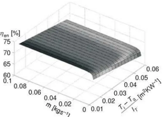
Obviously the temperature and mass flow rate of inlet water are the most effective operat-ing parameters in solar collectors. In heat pipe evacuated tube collectors, the heat transfer to the water is mainly done while the water is pass-ing through the manifold at the top of the collec-tor which touches the condenser wall. Conse-quently the variations ofTccan be considered as one of the effective parameters on collector per-formance. Figure 7 shows collector's energy ef-ficiency versus (Ti–Ta)/Iand mass flow rate of inlet water. As it is seen in this figure, energy ef-ficiency decreases with increasing inlet water temperature. An increase in inlet water
temper-ature leads to a decrease in the tempertemper-ature gradient between water and the outer wall of the con-denser. Therefore, the heat transfer rate between the condenser and the header water will de-crease.
As it is obvious in the other axis, an increase in the mass flow rate between 0 and 0.01 kg/s leads to an increase in heat transfer rate between condenser wall and header water. Therefore, the energy efficiency also increases. After that, in higher flow rates the convec-tion heat transfer coefficient between water and the heat pipe's condenser is almost constant. Therefore, the energy efficiency would also be constant.
Figure 8 shows collector's exergy efficiency vs. (Ti–Ta)/Iand mass flow rate of inlet water. Considering this figure, increasing inlet water temperature leads to an increase in exergy effi-ciency. The main part of exergy losses in solar collector is due to the temperature difference between the temperature of solar radiation as an exergy source and temperature of the collector's absorber surface. Increasing the water inlet temperature in heat pipe evacuated collectors leads to a decrease in heat transfer rate between the heat pipe's condenser and water. Conse-quentlyTcincreases. As it is seen in fig. 2,Tc andTehave a direct correlation so any increase inTcleads to an increase inTe. An increase in the absorber's surface temperature leads to a de-crease in the temperature difference between
the absorber and temperature of solar radiation. As a result of this, exergy losses will decrease. As it has been mentioned, an increase in the mass flow rate between 0 and 0.01 kg/s leads to an increase in heat transfer rate between condenser wall and header water. TheTewill also in-crease. Consequently, the exergy efficiency of the collector will dein-crease. At higher flow rates, constancy of the convection heat transfer coefficient between water and the heat pipe's con-denser leads to a stabilization of exergy efficiency.
Figure 7. Energy efficiencyvs. water mass flow
rate and (Tin–Ta/IT)
Figure 8. Exergy efficiencyvs.water mass flow
Conclusions
As far as the authors are aware there have been few if any, in depth research on exergy analysis of heat pipe evacuated tube solar collectors and most of the previous works focused on the flat plate collectors. Due to lack of sufficient research, using exergy and 2ndlaw concept in thermal analysis of the heat pipe evacuated collectors, a comprehensive model for these collec-tors was presented in this work. The model's accuracy was assessed by experiment.
While increasing the difference between water inlet and ambient temperature leads to a decrease in energy efficiency, it leads to an increase in exergy efficiency. The same process is observed about the variations of water inlet mass flow rate. It is also concluded that increasing water inlet temperature besides decreasing water mass flow rate results in a better exergetic per-formance.
Absorbing more solar radiation leads to better performance from both energy and exergy approaches. Making an improvement in the transmittance of tubes and absorptance of the absorber surface has a direct effect on collector performance.
Acknowledgments
The authors would like to acknowledge the financial support of Islamic Azad Univer-sity, South Tehran Branch (under contract No. B/16/778).
References
[1] Chow, T. T.,et al., Performance Evaluation of Evacuated Tube Solar Domestic Hot Water Systems in Hong Kong,Energy and Buildings, 43(2011), 12, pp. 3467-3474
[2] Mahdjuri, F., Evacuated Heat Pipe Solar Collector,Energy Conversion, 19(1979), 2, pp. 85-90 [3] Ayompe, L. M.,et al., Comparative Field Performance Study of Flat Plate and Heat Pipe Evacuated Tube
Collectors (ETCs) for Domestic Water Systems in a Temperature Climate,Energy, 36 (2011), 5, pp. 3370-3378
[4] Ribot, J., McConnell, R.D., Testing and Analysis of a Heat Pipe Solar Collector,Journal of Solar Energy Engineering, 105(1983), 4, pp. 440-445
Nomenclature A – area, [m2]
Ar – solar collector aperture area, [m 2
] Ap – solar collector absorber area, [m
2 ] cp – heat capacity of fluid, [Jkg
–1 K–1] D – diameter, [mm]
&
Ex – exergy flow rate, [W]
h – convection heat transfer coefficient, – [Wm–2K–1]
IT – solar irradiance, [Wm –2
] k – thermal conductivity, [Wm–1K–1] L – length, [m]
&
m – fluid mass flow rate, [kgs–1] &
Q – heat transfer rate, [W] R – thermal resistance, [KW–1] s – specific entropy, [kJkg–1K–1] T – temperature, [°C]
W – water, [–]
U – heat loss coefficient, [Wm–2K–1]
Greek symbols
e – emissivity, [–]
s – Stefan-Boltzmann constant, – [Wm–2K–4]
ta – effective transmittance – absorptance – product of absorber
Subscripts
a – ambient b – boiling c – condenser e – evaporator f – fluid i – inside in – inlet ma – manifold o – outside out – outlet rad – radiation T – total u – useful w – water
[5] Hull, J. R., Analysis of Heat Transfer Factors for a Heat Pipe Absorber Array Connected to a Common Manifold,Journal of Solar Energy Engineering, 108(1986), 1, pp. 11-16
[6] Ng, K. C.,et al., Outdoor Testing of Evacuated Tube Heat Pipe Solar Collectors,Proceedings,Institution of Mechanical Engineering, Part E:Journal of Process Mechanical Engineering, 214(2000), 1, pp. 23-30 [7] Jafarkazemi, F., Abdi, H., Evacuated Tube Solar Heat Pipe Collector Model and Associated Tests,Journal
of Renewable and Sustainable Energy, 4(2012), 2, pp. 023101-13
[8] Nkwetta, D. N.,et al., Experimental Performance Evaluation and Comparative Analyses of Heat Pipe and Direct Flow Augmented Solar Collectors,Applied Thermal Engineering, 60(2013), 1-2, pp. 225-233 [9] Dincer, I., Cengel, Y. A., Energy, Entropy and Exergy Concepts and their Roles in Thermal Engineering,
Entropy, 3(2001), 3, pp. 116-149
[10] Bejan, A., Fundamentals of Exergy Analysis, Entropy Generation Minimization, and the Generation of Flow Architecture,International Journal of Energy Research, 26(2002), 7, pp. 545-565
[11] Rosen, M. A., Dincer, I., Exergy Methods for Assessing and Comparing Thermal Storage Systems, Inter-national Journal of Energy Research, 27(2003), 4, pp. 415-430
[12] Farahat, S.,et al., Exergetic Optimization of Flat Plate Solar Collectors,Renewable Energy, 34(2009), 4, pp. 1169-1174
[13] Jafarkazemi, F., Ahmadifard, E., Energetic and Exergetic Evaluation of Flat Plate Solar Collectors, Re-newable Energy, 56(2013), Aug., pp. 55-63
[14] Languri, E. M.,et al., An Energy and Exergy Study of a Solar Thermal Air Collector,Thermal Science, 13 (2009), 1, pp. 205-216
[15] Ataee, S., Ameri, M., Energy and Exergy Analysis of All-Glass Evacuated Solar Collector Tubes with Co-axial Fluid Conduit,Solar Energy, 118(2015), Aug., pp. 576-591
[16] Kalogirou, S. A.,et al., Exergy Analysis on Solar Thermal Systems: A Better Understanding of their Sustainability,Renewable Energy, 85(2016), Jan., pp. 1-6
[17] Cengel, Y. A, Boles, M. A.,Thermodynamics an Engineering Approach, 5thed., McGraw-Hill, New York, USA, 2005
[18] Petela, R., Exergy of Heat Radiation,ASME Journal of Heat Transfer, 86(1964), 2, pp. 187-192 [19] ***, ISO 9806-1, Test Methods for Solar Collectors – Part 1: Thermal Performance of Glazed Liquid
Heat-ing Collectors IncludHeat-ing Pressure Drop, International Organization for Standardization, Geneva, Switzer-land, 1994