DOI: http://dx.doi.org/10.1590/1516-1439.292714
Materials Research. 2014; 17(5): 1324-1327 © 2014
*e-mail: [email protected]
1. Introduction
Friction Stir Welding (FSW) is a solid-state welding technique that has emerged as one of the most important joining processes with a vast application potential in aerospace, automotive and shipbuilding industries1,2.
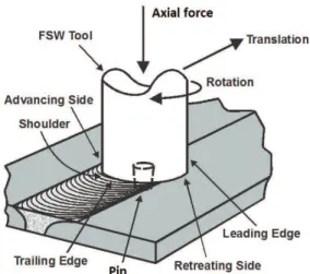
Its basic concept is remarkably simple. In FSW, a non-consumable rotating tool is inserted into the abutting edges of sheets or plates to be joined and traversed along the line of joint2. The FSW tool consists of a pin and a shoulder. The pin
is designed to disrupt the faying surfaces of the workpiece, shear material in front of the tool, and move material behind
the tool. The shoulder is needed to generate suficient heat, allowing material low around the tool. Figure 1 shows a schematic illustration of the FSW process. Considering its potential, the weld formation mechanisms associated with FSW must be clearly understood, especially the axial force behavior during FSW. Without an adequate axial force acting through the tool, the forging of the plastically deformed material would not occur properly and voids would form2.
Several researches on FSW have already examined the effect of two major weld parameters - rotation speed (RS) and transverse speed (TS) - to justify the quality of the welds. Meran et al.3 conducted a study of AISI 304 austenitic
stainless steel, at a tool rotation speed of 1000 rpm and welding speeds of 40-100 mm per min. They found that defect-free FSW were produced under a wide range of welding speeds. Reynolds et al.4 conducted a similar study
using AISI 304L austenitic stainless steel at two rotational speeds, 300 rpm and 500 rpm, and welding speed of 100 mm per min. Sound welds were obtained for both combinations of parameters, however, the 300 rpm weld exhibited higher strength than the 500 rpm.
Typically, rotation speed and traverse speed are independently controlled. However, when plunge depth is also independently controlled, the axial force becomes a
function of the other three parameters5. In that case, when
RS, TS and PD are kept constant, abnormal or abrupt axial force oscillations can be associated with the loss of material in the nugget , leading to the formation of volumetric
defects. Therefore, the purpose of this work is to conirm the
possibility of predicting FSW defect-free joints of 304 SS,
by analyzing and understanding axial force proiles, whilst
other parameters are independently controlled and kept constant.
2. Experimental Procedure
Plates of 304 SS with thickness of 2.5 mm were
friction-stir welded in butt joint coniguration, using a MTS
three-axis gantry system. Table 1 shows the experimental chemical composition of the as-received material. The plates were reduced to rectangular specimens of 100 mm × 150 mm. In order to prevent the surface oxidation, argon shielding gas
was employed around the tool at a low rate of 20 L/min. To
produce the welds, a Polycrystalline Cubic Boron Nitride (PCBN) tool (with a shoulder and a cylindrical pin of 15 mm and 10 mm in diameter, respectively) and a W-25%Re tool (with a shoulder and a 45° conical pin of 13 mm and 6 mm in diameter, respectively) were utilized.
The speciic combinations of parameters and tools
presented in Table 2, based on preliminary research, were investigated. The process was operated in a position-controlled mode, so that axial force varied to maintain plunge depth in 2.4 mm. The tilt angle of the tool was kept constant at 0° during the welding process.
Transverse weld cross-sections were cut by electrical discharge machining for metallographic analysis in the positions of interest. After metallographic preparation, the samples were electrolytically etched in a solution of 10% oxalic acid and 90% distilled water with a power supply set at 19 V, during 18 s. Microstructure was observed by optical microscopy for the cross-sections of the joints.
Prediction of Friction Stir Welding Defect-Free Joints of AISI 304 Austenitic
Stainless Steel Through Axial Force Proile Understanding
Athos Henrique Plaine*, Nelson Guedes de Alcântara
Department of Materials Engineering, Federal University of São Carlos – UFSCar, Rod. Washington Luiz, Km 235, CP 676, CEP 13565-905, São Carlos, SP, Brazil
Received: September 5, 2014; Revised: September 9, 2014
Friction Stir Welding (FSW) joints of AISI 304 austenitic stainless steel (304 SS) using position controlled mode were investigated in order to understand and relate axial force behavior to welding
quality. Joints were produced using two tools and four combinations of speciic parameters. The results showed coherence between the axial force proiles and the low-magniication overviews of
the welded joints. For defect-free joints, only a natural oscillation on axial force occurred after tool plunge. In contrast, abnormal or abrupt oscillations were directly associated with common welding defects, such as voids and nugget collapse.
2014; 17(5) 1325
Prediction of Friction Stir Welding Defect-Free Joints of AISI 304 Austenitic
Stainless Steel Through Axial Force Proile Understanding
3. Results and Discussion
3.1. Axial force proile – defect-free joints
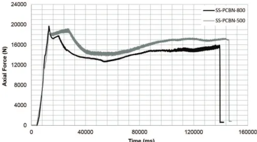
Figure 2 shows axial force versus time curves, during FSW process for defect-free joints. Both curves exhibit a similar behavior. At the beginning, when the tool plunges deeper into the material, metal has to be displaced from
underneath the tool. In order for the metal to low out from
underneath the tool, it has to overcome the restraining forces
of the die cavity. Thus, suficient pressure gradient has to be developed along the metal low path. The channel of metal begins underneath the pin and lows outward and upward
to the edges of the shoulder. When the tool is not plunging, the pressure along this channel is in equilibrium, therefore, no metal is displaced. However, when the tool starts to plunge downwards, a large pressure gradient begins to build up on the metal along this channel. This pressure increase is balanced by an increase in axial force. The pressure is
greatest underneath the pin, but as the low channel gets
further away from the pin bottom and closer to the surface, it decreases. At the outer edge of the shoulder, the pressure naturally becomes zero because the metal no longer has
to low out from underneath the tool. Once the metal is
displaced and the tool reaches its new plunge depth, the pressure gradient returns to a steadystate equilibrium. From this point on, an oscillation of axial force and corresponding pressure underneath the tool would just occur if the radius
and volume of rotating metal oscillated. In the case of any material loss, a weld nugget free of voids cannot be formed and the materials cannot be reliably joined. Nevertheless, only natural oscillations - theorized based on the coupling
between shear low stress, deformation, axial pressure and temperature - were observed in both curves, being the irst
indicative of defect-free joints.
Figure 3 presents low magniication overviews of SS-PCBN-500 and SS-PCBN-800. The weld seams exhibit a satisfactory visual aspect in both samples and cross-section
macrographs demonstrate no volumetric defects, conirming
in theory that defect-free joints are related to the continuity of the axial force curves.
As the tool rotates faster, it can also be concluded that the additional heating generates higher temperatures and softer conditions within the metal, lowering the required axial force. As the material temperature rises with the frictional heating and plastic deformation, the atoms move further apart. The greater spacing between atoms results in a softer metal, which requires less pressure from the tool to forge together the two parent metals for a given plunge depth. However, according to Cook et al.5, there is a
drawback in increasing rotation rate. At high rotational rates,
an undesirable weld lash can be created when the metal is
detached and expelled from underneath the shoulder of the rotating tool; the shoulder surface shears off a thin layer of
the material, which is referred to as weld lash.
3.2. Axial force proile – no defect-free joints
Figure 4 shows the axial force versus time curves during the FSW process for no defect-free joints. Figure 5 presents
low magniication overviews of the welded joints.
The cross-section macrograph of SS-WRe-400 (Figure 5a) shows a lack of consolidation of the material inside the weld nugget, which is the most common defect found in FSW, known as void or wormhole. It was caused by cold processing conditions due to the combination of traverse speed, tool rotation, plunge depth and resulting
insuficient axial force. Voids create porous conditions,
which negatively affect the structural integrity of the weld.
Facing insuficient force, the friction between the tool
shoulder and the material is reduced, leading to less heat generation and lower temperatures inside the die cavity. The lack of heat does not aid the deformation of the material because the material remains in a hardened state. In addition, the colder welding condition does not promote the mixing and forging of the plasticized material. These facts caused
Table 1. Chemical composition of 304 SS sheets.
Element Fe Cr Ni Mn Si C N P
wt.% Bal. 18.40 8.15 1.60 0.42 0.08 0.05 0.03
Table 2. Parameters speciications.
Join speciication Tool Rotational speed (rpm) Welding speed (mm/s) Plunge depth (mm)
SS-PCBN-500 PCBN 500 2 2.4
SS-PCBN-800 PCBN 800 2 2.4
SS-WRe-400 W-25%Re 400 2 2.4
SS-WRe-600 W-25%Re 600 2 2.4
Plaine & Alcântara
1326 Materials Research
Figure 2. Proiles of axial force versus time of defect-free welded joints.
Figure 3. Macrographs of top surface and cross-section of joints: (a) SS-PCBN-500 and (b) SS-PCBN-800. The black lines on the top surfaces indicate the sections of cut.
Figure 4. Proiles of axial force versus time of no defect-free welded joints.
2014; 17(5) 1327
Prediction of Friction Stir Welding Defect-Free Joints of AISI 304 Austenitic
Stainless Steel Through Axial Force Proile Understanding
an abnormal oscillation of axial force after the plunge. Consequently, axial force continues to increase, seeking to reach its stability. However, the steady-state equilibrium value was only achieved at the end of the process.
According to the model proposed by He et al.6, porosity
tends to be formed in the advancing side, very close to the pin. The wormholes and voids can be minimized by rising the axial force of the FSW tool, which is made possible by increasing the heat inside the die cavity. The heat increase will cause the metal to become softer and the voids may collapse. Considering this, another attempt was performed by increasing the rotation speed from 400 rpm to 600 rpm in order to increase the heat input of the process. However, caution should be taken when arbitrary adjusting the processing parameters to create hot processing conditions. When the process becomes excessively hot, defects such as
a root-low and nugget collapse can occur. The beginning of
the top surface of SS-WRe-600 showed an evident nugget collapse. This defect was caused by a large amount of
material low from underneath the shoulder to the advancing
side due to the excessive heat achieved during plunge, which resulted in a loss of cross sectional area of the weld joint, producing less load bearing capability. The collapse was
directly relected on the axial force proile, being evidenced
by an abrupt oscillation on the curve. Nevertheless, as the tool started to travel far from the initial point, the heat input reduced and the equilibrium was achieved. After this point, only the natural axial force oscillation was observed. As expected, the cross-section macrograph of SS-WRe-600, extracted from a position of steady-state equilibrium, presented no apparent internal defects.
4. Conclusions
The possibility of predicting defect-free weld by analyzing and understanding AISI 304 austenitic stainless steel axial force profiles during FSW, using position-controlled mode, was investigated. The conclusion was
that axial force is the irst indicative of defect-free welds,
which can be related to the continuity of the axial force versus time curve. Any deviation from the natural oscillation must be considered and can be associated with internal or external welding defects, such as voids and nugget collapse.
Therefore, internal defects can be identiied through axial force proile observations, even when weld seam exhibits
a satisfactory visual aspect. The same conclusions seem to be reasonable for other types of metals.
References
1. Nandan R, Debroz T and Bhadeshia HKDH. Recent Advanced in friction stir welding – process: weldment structure and properties. Process Mater Sci. 2008; 53(6):980-1023.
2. Mishra RS and Ma ZY. Friction stir welding and processing. Materials Science and Engineering. 2005; 50(1-2):1-78. http:// dx.doi.org/10.1016/j.mser.2005.07.001.
3. Meran C, Kovan V and Alptekin A. Friction stir welding of AISI 304 austenitic stainless steel. Materialwissenschaft und Werkstofftechnik. 2007; 38(10):829-835. http://dx.doi. org/10.1002/mawe.200700214.
4. Reynolds AP, Tang W, Gnaupel-Herold T, Prask H, Gnaupel- Herold T and Prask H. Structure, properties, and residual stress of 304L stainless steel friction stir welds. Scripta Materialia. 2003; 48(9):1289-1294. http://dx.doi.org/10.1016/S1359-6462(03)00024-1.
5. Cook G, Crawford R, Clark D and Strauss A. Robotic Friction Stir Welding. The Industrial Robot. 2004; 31(1):55-63. http:// dx.doi.org/10.1108/01439910410512000.