Towards a Roadmap for the Migration of Legacy Software Systems to a
Microservice based Architecture
Hugo H. O. S. da Silva
1, Glauco de F. Carneiro
1and Miguel P. Monteiro
21Programa de Pós-Graduação em Sistemas e Computação (PPGCOMP), Universidade Salvador (UNIFACS), Salvador 41770-235, Brazil
2NOVA LINCS, Faculdade de Ciências e Tecnologia Universidade Nova de Lisboa (FCT/UNL), 2829-516 Caparica, Portugal
[email protected], [email protected], [email protected]
Keywords: Monolithic Legacy Systems, Exploratory Study, Microservices.
Abstract: The migration of legacy software systems to a microservice based architecture is not a trivial task due to chal-lenges and difficulties as reported in the literature. The concept of microservices mainly consists in software organized as a suite of small, modular, and independently deployed services that run on their own processes and communicate through well-defined, lightweight mechanisms to serve a business goal. However, the litera-ture is still incipient in relation to step-by-step guidelines supporting practitioners to accomplish the migration from an existing, monolithic structure to a microservice based architecture. Goal: Discuss lessons learned from the migration of legacy software systems to microservices-based architecture. Method: We conducted two studies (a pilot and a case study) aiming at characterizing the relevants steps of such guidelines. Results: We report the steps and challenges observed during the migration reported in this study. Conclusion: We identify at least three main phases that drive the migration process.
1
INTRODUCTION
Microservices is an architectural style based on the service-oriented computing approach (Dragoni et al., 2017). Their main goal is to efficiently build and manage complex software systems (Singleton, 2016). Among the main promises for the adoption of a microservices-based architecture, we can list the fol-lowing: to yield cost reduction, quality improvement, agility, and decreased time to market. Microservices can be compared to the software equivalent of Lego bricks: they are proven to work, fit together appropri-ately, and can be an option to build up complex so-lutions in less time than with traditional architectural solutions (Singleton, 2016).
In the past, a representative number of legacy soft-ware systems moved to the cloud keeping the same ar-chitecture in the new infrastructure. The practical out-come of this fact is that most of these legacy software systems have been originally placed in virtual machi-nes and deployed in the cloud, assuming the charac-teristics of resources and services of a traditional data center (Silva et al., 2019). This approach fails to re-duce costs, improve performance and maintainability (Toffetti et al., 2017).
The issue remains, of which steps that should be
followed to migrate a monolithic legacy system to a microservices-based architecture. To the best of our knowledge, despite the relevance of this topic, it has drawn the attention of just researchers (Kalske et al., 2017) (Leymann et al., 2016) (Taibi et al., 2017). To fill this gap, we present the lessons learned of our ex-perience in the migration of two legacy systems. The lessons learned are the result of a two-phase study to address the following Research Question (RQ): Which steps should be performed to support the mi-gration of legacy software systems to microservices-based architecture? Availability of lessons learned can help practitioners from industry and academia in the migration of legacy systems to microservices. They can also contribute to encourage practitioners to embrace this challenge.
The rest of this paper is organized as follows. Sec-tion 2 discusses the main shortcomings of a mono-lithic legacy system and maps them to possible soluti-ons provided by the microservice-based architecture. Next, section 3 introduces a two-phase study. Section 4 describes the first phase, which is a pilot study ai-med at identifying key steps of the migration process as well as improvement opportunities. Section 5 re-ports on the second phase, which is a case study focu-sed on applying a reviewed and improved version of
the steps performed in the first study. Section 6 pro-poses a migration roadmap based on the insights gai-ned from the pilot and case studies. Section 7 reports lessons learned. Section 8 discusses opportunities for future research and provides concluding remarks.
2
MONOLITHIC VS
MICROSERVICES
The adoption of single executable artefacts or mono-lithswith the corresponding modularization of their abstractions is based on the sharing of resources of a specific computer system (memory, databases, fi-les, among others) (Dragoni et al., 2017). Consi-dering that components of a monolithic system de-pend on shared resources, they are not indepen-dently executable (Dragoni et al., 2017)(Richardson, 2014a)(Richardson, 2014b). In general, monolithic systems of large size are not easily maintained and evolved due to their inherent complexity (Dragoni et al., 2017). In most cases, dealing with software bugs in these scenarios requires a strong joint ef-fort and is thus likely to have a negative impact on team productivity (Dragoni et al., 2017). Add to this the fact that to add or update libraries are likely to produce inconsistent systems that either do not com-pile/run or worse, misbehave (Dragoni et al., 2017).
Carrying out a change on a monolithic system en-tails the re-building of the whole application. As the system evolves, it becomes ever more difficult to maintain it and keep track of its original architec-ture1. This can result in recurring downtimes,
speci-ally for large-sized projects, hindering development, testing, and maintenance activities (Dragoni et al., 2017). Monolithic systems under these conditions are prone to stop working and become unable to provide part or all of their functionality. They also suffer from scalability issues.
In order to deal with the shortcomings of this type of applications, and to handle an unbounded number of requests, developers create new instances of them and split the load among these instances. Unfortuna-tely, this approach is not effective, since the increased traffic will be targeted only to a subset of the modules, causing difficulties for the allocation of new resources for other components (Dragoni et al., 2017).
Microservices should be small and indepen-dent enough to allow the rapid development, (un)pluggability, harmonious coexistence and inde-pendent evolution. Microservices have been referred
1https://www.thoughtworks.com/insights/blog/ microservices-nutshell
as a solution to most of the shortcomings of mono-lithic architecture. They use small services to remove and deploy parts of the system, enable the use of dif-ferent frameworks and tookits and to increase scala-bility and improve overall system resilience.
In the context of this paper, the "micro"prefix isn’t really too important. Rather than being about size, it relates to keeping the various services separate. This becomes important when working with hundreds of services. A microservice architecture can make use of the flexibility and better pricing model of cloud en-vironments (Balalaie et al., 2016).
To illustrate the advantages that stand out when using microservices, we next show a non-exhaustive list: cohesive and loosely coupled services (Wolff, 2016); independent implementation of each microser-vice and thus enhanced system adaptability (Millett, 2015); independence of multifunctional, autonomous and organized teams that provide commercial value in addition to improved technical characteristics (Mil-lett, 2015); independence of domain concepts (Wolff, 2016); freedom from potential side effects (SPoF) across services; encouragement of the DevOps cul-ture (Balalaie et al., 2016), which basically repre-sents the idea of decentralizing skills concentration into multifunctional teams, emphasizing collabora-tion between developers and teams, ensuring reduced lead time and greater agility during software develop-ment.
3
A TWO-PHASE STUDY
Exploratory studies like the two-phase explora-tory study reported here are intended to lay the groundwork for further empirical work (Seaman, 1999). In this case, the goal to identify the relevant and effective steps for the migration of legacy sys-tems to a microservices-based architecture. This sec-tion describes its design and settings.
The present study aims to address the following research question (RQ): What would be the set of effective steps to migrate legacy systems to a microservices-based architecture? The specific rese-arch questions (SRQ’s) derived from the base RQ are as follows: SRQ1: How to find features in a legacy application so that they can be subsequently modu-larized and become a candidate to a microservice-based architecture? SRQ2: How to migrate the best candidate features to a microservice-based architec-ture?
The study protocol followed for this study is as follows. The first author of this paper carried out the tasks of the reported study, after discussing the
strategies, experiences and impressions with the other two authors. To answer the research questions (pri-mary and secondaries), all steps registered by the first author in manuscripts were analyzed.
To select suitable subject systems for the study, it was decided that candidate applications should match the following characteristics: (1) be a legacy applica-tion, (2) have a monolithic architecture that does not have its functionalities modularized, (3) show symp-toms of scattering and tangling, and (4) correspond to the symptoms described by the Big Ball of Mud anti-pattern (Coplien and Schmidt, 1995).
We also outlined what was expected of the study’s outcomes. The evolved version was expected to be more coherent than before the migration, be more lo-osely coupled and its modular decomposition should more aligned to the services it provides (Newman, 2015). We also expected to observe an increase in the autonomy of developing teams within the organi-zation, as new functionalities can be localized within specific services (Newman, 2015).
3.1
Key Concepts from Domain Driven
Design
We used key Domain-Driven Design (DDD) concepts to accomplish the tasks of this study. DDD was used to translate functionalities into domain and subdo-main and thereby support the migration.
A Bounded Context is a subsystem in the solu-tion space with clear boundaries distinguishing each subsystem (Evans, 2004). Bounded Context aids in the separation of contexts to understand and address complexities based on business intentions.
In the broad sense, Domain comprises all relevant knowledge relating to the problem that is intended to be solved. It can refer to either the entire Business Do-main, or just a basic or support area. In a DoDo-main, we try to turn a technical concept with a model (Domain Model) into something understandable. The Domain Model is the organized and structured knowledge of the problem. It should represent the vocabulary and main concepts of the problem domain and identify the relationships between the various entities. It is expec-ted to serve as a communication tool for all involved, giving rise to a very important concept in DDD, which is Ubiquitous Language. The model could be a dia-gram, code examples or even written documentation of the problem. The important thing is that the Do-main Modelmust be understandable and easy to ap-proach by all people involved in the project.
A Context Map is a high-level diagram showing a collection of connected contexts and the relationships between them (Evans, 2004). The goal of the
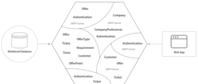
ag-Figura 1: Entities and Associated Features Scattered and Tangled in ePromo (Silva et al., 2019).
gregate rootis to select the object that serves as the "root"of a group of other objects, in a abstract manner of a Façade (Gamma, 1995) to represent the whole structure. On the other hand, the value object can comprise simple or composite values with a business meaning.
4
THE PILOT STUDY
The subject of the pilot study is ePromo, a system that comprises a typical example of a corporate/business coupon web system implemented in the PHP program-ming language for the management of outreach cam-paigns. The web server is Nginx, whose features in-clude the creation of personalized offers and issuance of tickets made by the customer. All functionalities are implemented in a large artifact, connected to a sin-gle relational database (MySQL), whereas Memcached is used as a memory cache system, including data re-lated to the sessions - signs of a monolithic applica-tion. Due to the sudden growth of demand for cou-pons, the application started to face problems in this specific component, which led to interruptions in the system operation.
The specific research question SRQ1 says: find features to be subsequently modularized and turned into microservice candidates. To answer it, the par-ticipant applied a manual identification of candidate features and their respective relationships, by na-vigating among the directories and files and iden-tifying the purposes of each class. Figure 1 illustra-tes the identified entities, which in the beginning of the pilot study were: Offer, OfferPoint, Ticket, Requirement, Timer, User, Company. By analysing the features associated to these entities, we acquired an initial perception of how they are tangled and scat-tered in the code. In fact, the functionalities are the reference to build the Context Map. It is worth menti-oning that it was possible to recognize the entities and the candidates for value object’s and aggregate roots during elaboration of the Context Map, on the basis of the information retrieved from the source code. At
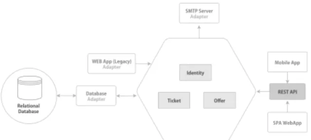
Figura 2: ePromo System Context Map in the Pilot Study (Silva et al., 2019).
this time, we had the opportunity to spot code tigh-tly coupled to the web framework, right at the initial browsing stage.
The migration process was carried out one feature at a time, based on the list of features. We started with the functionality that would have lowest impact when compared to the others. This process facilita-tes the validation of boundaries set between features with the least risk of side effects. Considering that the business rules were scattered throughout the con-trollers with significant duplication, additional effort was necessary to identify the various functionalities involved. Note that this is a manifestation of tangling. During analysis, we noticed that artifact TicketsController had many responsibilities and its business rules seemed scattered. It needed extensive refactoring, including extraction of clear layers for different levels of abstraction. Each layer would be represented by a folder, which entailed structural changes at that level, within the repository’s source root. New directories were created for system: Application, Domain and Infrastructure. Folder Applicationis to be devoid of business logic and made responsible for connecting the user interface to the lower layers. In sum, the application layer will be able to communicate with the domain layer, which will act as a sort of public API for the application. It will accept requests from the outside world and return answers appropriately. Folder Domain is to harbour all concepts, rules and business logic of the application, such as the user entity or the user repository. These files will be stored according to the context identified in previous steps. Folder Infrastructure is to host the implementations concerning technical features, which provide sup-port to the layers above, namely persistence, and communication over networks.
The Command pattern (Gamma, 1995) encapsula-tes a request as an object, thereby parametrizing
cli-Figura 3: ePromo Modularized Version (End of the Pilot Study) (Silva et al., 2019).
ents with different requests, queue or log requests, and support undoable operations (Gamma, 1995). We applied Command to minimize coupling and deal with the tangled code with scattered business rules and identified in the controllers of the application. Ba-sed on TicketController, Command was uBa-sed to uncouple the controller from the user interface logic. When looking at the command objects, we should be able to spot the goal of the code snippet they enclose. The controller is intended to pass just the information needed by the command - CreatingTicket in this case - to forward to the handler, which is to handle the acceptance of the command and complete its task. Using Command brings several advantages. First, the functionality can run in any part of the application. Second, the controller will no longer have business rules, doing just what is proposed above. Third, the tests are easier to make, as a result of decoupling. The new version of the modularized system is presented in Figure 3.
4.1
Lessons Learned from the Pilot
Study
The experience gained in the pilot study enabled us to answer the specific research question SRQ1. In Sec-tion 4, we point out the identificaSec-tion of funcSec-tiona- functiona-lities faced difficulties due to lots of scattered clas-ses and duplicated business rules. This situation is typified as the Anemic Model anti-pattern2. There-fore, identifying business resources requires much ef-fort than otherwise would be the case.
During identification and mapping of business contexts, we noticed that despite the sudden growth of demand for coupons, the number of features can-didates for microservices is not necessarily indicative of the use of a microservice architecture. There is not a positive trade-off between the advantages of micro-services and the corresponding costs and effort requi-red to manage it (Singleton, 2016).
2https://martinfowler.com/bliki/AnemicDomainModel. html
Although microservice approaches offer substan-tial benefits, the corresponding architecture requires extra machinery, which may also impose substantial costs (Singleton, 2016). This also gives rise to gre-ater complexity, which is incompatible with the rela-tive simple scenario now perceived through the map of contexts. Therefore, a decision to carry out a mi-gration should consider the extra effort required to work with issues such as automated deployment, mo-nitoring, failure, eventual consistency, and other fac-tors introduced by a microservice architecture. In the case of ePromo, we decided not to opt for the migra-tion, keeping it in its new modularized version, for the above reasons.
The preliminary list of lessons learned reached at this point comprises two main parts: part 1 is related to the restructuring of the legacy system to a modu-larized version and part 2 is related to the migration of the modularized version, to microservices. Part 1 of the lessons learned are related to the (1a) identifi-cation of candidate functionalities that can be modu-larized in legacy applications; (1b) analysis of rela-tionships and organizational dependencies in the le-gacy system; (1c) identification of each domain and sub-domain. Part 2 of the lessons learned relates to the (2a) selection of the candidates according to their importance to the domain and the application itself; (2b) conversion of the candidate functionalities to mi-croservices.
5
THE CASE STUDY
In this case study, we aim at analyzing an effective manner to look for candidate features to be modula-rized in legacy software systems to be later migrated into microservices. The subject system is eShop, an online store in which users can browse a product ca-talog.
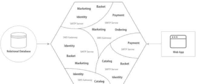
Figure 4 illustrates a typical scenario of eShop. The system provides functionalites such as user authentication, catalogue of products, special offers, and payments. The features of the monolithic ap-plication are implemented in the PHP programming language in a single "big module", connected to a (MySQL) relational database. The system runs as a single artifact on a Nginx web server. The size of the source code increased dramatically over the ye-ars, as stakeholders asks for ever more changes and new functionalities. To deal with such requests, velopers struggled to deliver new releases, which de-manded ever more effort.
Part I of the process consists of migrating the le-gacy system to a modularized version. To carry it out,
Figura 4: A Traditional Monolithic Legacy Software Sys-tem (Case Study) (Silva et al., 2019).
we first "manually"identified the candidate functiona-lities by navigating among the directories and files to find out the goal of each artifact likewise the pilot study. Figure 4 shows the entities Identity, Basket, Marketing, Catalog, Ordering and Payment rela-ted to the identified functionalities. This is the out-come of the first step aimed at identifying the main functionalities and responsabilities in view of a tenta-tive establishment of boundaries between them. Next, we planned to break down the main module into units. The key to this task was the use of Bounded Con-textsans their respective relationships, as represented in Figure 5. We applied in each Bounded Context the following DDD key concepts: aggregate root, value objectsand domain services. These concepts support the challenge to deal with manage domain complexity and ensures clarity of behavior within the domain mo-del.
After the acknowledgement of contexts, we orded them by level of complexity, starting with the low le-vel ones to validate the context mapping. Moreover, we positioned the contexts into well-defined layers, expressing the domain model and business logic, eli-minating dependencies on infrastructure, user inter-faces and application logic, which often get mixed with it. We managed to set all the code related to domain model in one layer, isolating it from the user interface, application and infrastructure parts (Evans, 2004). In some situations, we can apply the Strangler pattern (Taibi et al., 2017) to deal with the complexity of the module to be refactored. Consiedering that fea-tures are moved to new modules or a new system, the legacy system will be totally "strangled"to the point where it will no longer be useful.
A folder should be created for each of the Boun-ded Contexts and within each folder, three new fol-ders should be added, one for each layer: Domain, Application, Infrastructure. They contain the source code necessary for this Bounded Context to work. It is crucial to consider the domain models and their invariants and to recognize entities, value objects and also aggregate roots. We should main-tain the source code in these folders as described
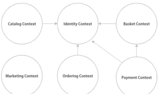
Figura 5: A Context Map for the Monolithic Legacy Soft-ware System (Case Study) (Silva et al., 2019).
Figura 6: An Evolved Monolithic Legacy System (Case Study) (Silva et al., 2019).
in the sequence. Folder Application contains all application services, command and command han-dlers. Folder Domain contains the classes with exis-ting tactical patterns in the DDD, such as: Entities, Value Objects, Domain Events, Repositories, Factories. Folder Infrastructure provides tech-nical capabilities to other parts of the application, iso-lating all domain logic from the details of the infras-tructure layer. The latter contains, in more detail, the code for sending emails, post messages, store infor-mation in the database, process HTTP requests, make requests to other servers. Any structure and library re-lated to "the outside world", such as network and file systems, should be used or called by the infrastructure layer.
Part II of the process consists of migrating the mo-dularized version to a microservices-based version. At this point, the focus is on the analysis of the previ-ously developed Context Map and the assessment of the feasibility of decomposing each identified context into microservice candidates. In this case, during the analysis of the Context Map, it is required to unders-tand and identify the organizational relationships and dependencies. This is analogous to domain modeling, which can start relatively superficially and gradually increase levels of detail.
At this point, we wanted to decompose an appli-cation into smaller parts. The most common way to do this is based on layered segmentation based on
user interface, business logic and database responsi-bilities. However, this is prone to give rise to coupling between modules, causing the replication of business logic in the application layers (Dragoni et al., 2017) - coupling defines the degree of dependency between components or modules of an application. The micro-service proposal to circumvent this problem entails segmenting the system into smaller parts with fewer responsibilities. In addition, it also considers domain, focus and application contexts, yielding a set of auto-nomous services, with reduced coupling.
To provide answers to the specific research ques-tion SRQ2, the Bounded Contexts from DDD are used to organize and identify microservices (Nadareishvili et al., 2016). Many proponents of the microservice architecture use Eric Evans’s DDD approach, as it of-fers a set of concepts and techniques that support the modularization in software systems. Among these to-ols, Bounded Context is used to identify and organize the microservices. Evans made the case for Boun-ded Contexts as facilitating the creation of smaller, more coherent and more cohesive components (mo-dels), which should not be shared across contexts. In the Context Map shown in Figure 5, the arrow is used to facilitate identification of upstream/downstream re-lationships between contexts. When a limited context has influence over another (due to factors of a less te-chnical nature), provision of some service or informa-tion this relainforma-tionship is considered upstream. Howe-ver, the limited contexts that consume it comprise a downstream relationship (Evans, 2004).
An effective way of defining microservice boun-daries entails correctly identifying the Bounded Con-texts, using DDD and breaking a large system across them. Newman points out that Bounded Contexts re-present autonomous business domains (i.e., distinct business capabilities) and therefore are the appropri-ate starting point for identifying boundaries for micro-services. Using DDD and Bounded Contexts lowers the chances of two microservices needing to share a model and corresponding data space, risking a tight coupling.
Avoiding data sharing facilitates treating each mi-croservice as an independent deployment unit. Inde-pendent deployment increases speed while still main-taining security within the overall system. DDD and Bounded Contextsseems to make a good process for designing components (Newman, 2015). Note howe-ver, that it is still possible to use DDD and still end up with quite large components, which go against the principles of the microservice architecture. In sum, smaller is better.
The number of responsibilities is an important ser-vice feature. This is reinforced by the Single
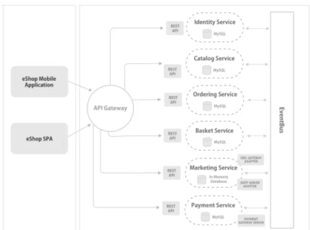
Respon-Figura 7: A New Based Microservices Software System (Case Study) (Silva et al., 2019).
sibility Principle(SRP) (Martin, 2002). Each service must have a well-defined boundary between the mo-dules, which should be independently created and pu-blished, through an automated deployment process. A team can work on one or several Bounded Contexts, with each serving as a foundation for one or several microservices. Changes and new features are suppo-sed to related to just one Bounded Context and thus just one team (Wolff, 2016).
The strategy is to move resources vertically by de-coupling the primary feature along its data and redi-rect all front-end applications to the new APIs. Ke-eping all data on a single basis is contrary to the de-centralized data management feature of microservi-ces. Having multiple applications using the data from a centralized database is the primary step to decouple the data along with the service.
During the migration of the eShop database, we decided to execute it in incrementar steps due to its inherent complexity. Migrating data from a legacy software system requires careful planning, depending on each case. In the case of the aforementioned da-tabase, we identified the tables corresponding to each service and created a new database schema (MySQL) for each of the corresponding services. We then mi-grated one service at a time. The database did not seem to be particularly large and this approach was applied without side effects. However, this may not be the best approach, depending on the size of the da-tabase to be migrated. Each specific scenario must be analyzed addressing their own specificities and com-plexities scenarios. To perform the migration, we adopted the Doctrine Migrations3tool. Figure 7 con-veys the architecture of the new microservices based architecture system.
3https://www.doctrine-project.org/projects/migrations .html
6
PROPOSED MIGRATION
ROADMAP
The purpose of the roadmap is to migrate a system with monolithic legacy architecture to a microservice architecture. A level of discipline and some skills are necessary in the operational part, as described in the next sections.
Traditional monolithic legacy software systems usually show signs of deficient modularity, resulting in significant levels of tangling and scattering. Most of the time, a complete system rewrite from scratch is infeasible. It is therefore recommended to migrate the legacy system gradually, replacing specific parts of it with new modules. This type of approach is already discussed in the Strangler pattern (Taibi et al., 2017). Upon completing the migrating process, the older version of the legacy system is discarded. Therefore, it is important to note that this approach helps mini-mize risk during migration and distributes develop-ment effort over time.
6.1
Roadmap Premises
A first assumption or requirement to use the proposed roadmap, is that the target system has a monolithic architecture. At least three layers should be identified on it: presentation layer, business layer and data layer. It is also important that the developer or development team have a minimum knowledge of the system’s bu-siness rules, which will be critical during execution of phases 1 and 2, which focus on the extraction of kno-wledge from the domain and on establishing limits consistent with the system’s business rules.
Fast Deployment. How the microservice archi-tecture promotes the creation of independent services; it is necessary to automate the deployment of these services to save time for developing teams in different environments, e.g., development, testing and produc-tion environments.
Provisioning Environments. Given the need to automate the deployment process, we also feel the need of a fast provisioning environment, which fits nicely with Cloud Computing.
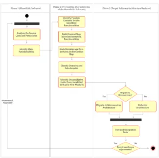
The structure of the roadmap is as follows. Phase 1 analyzes and identifies of key functionalities and their respective responsibilities. Phase 2 details the pre-existing characteristics of the monolithic system, using some of the key concepts of Domain-Drive De-sign (DDD), such as: Delimited Context, Context Map, Domains, Subdomains, Aggregator, Value Ob-jects, and Services Domain. These concepts help to build artifacts that support migration decisions to be made, including granularity and cohesion of services
Figura 8: Roadmap Premises Workflow.
to be implemented. Phase 3 promotes the migration to a microservice architecture of the Bounded Contexts identified and mapped in the previous phase.
6.2
Phase 1: Monolithic Software
Step 1: Analyze Source Code and Database Input Data: Source Code and Database Output Data: Source Code and Database Description of Step 1: The first phase is initia-ted by the process of identifying the artifacts in the system. This step analyzes the source code and the database legacy system. To perform this analysis it is necessary to navigate between the files and directories of the system, to obtain a clearer view of the domain under analysis.
Step 2: Identify Main Functionalities Input Data: Source Code and Database Output Data: List of Identified Funcionalities Description of Step 2: This step identifies the purposes, responsibilities and main functionalities of the artifacts. It is important to emphasize that this is an iterative and incremental process. At this first stage, it is essential to document it, even if it means simply using a list to record what was identified while browsing the system artifacts. The next step is to es-tablish a temporary boundary between the various fe-atures, where the goal is to ensure more clarity and understanding of the system’s business rules.
Figura 9: Simple Draft Diagram with Subdomains Identi-fied.
6.3
Phase 2: Pre-existing
Characteristics of Monolithic
Software
Step 3: Identify Domains and Subdomains of Mapped Functionalities
Input Data: List of Identified Funcionalities Output Data: Diagram with Identified Subdo-mains
Description of Step 3: In this step, the goal is to distill the domain to provide an ever deeper kno-wledge. Therefore, it is important to create a domain model, which is a high-level artifact that reveals and organizes domain knowledge data with the intent of providing clear language for developers and domain experts. This effort can be collaborative, involving the development team and domain specialists and sta-keholders. It is important for this task to comprise the outlining of a simple diagram, without formalities, as its goal is to be clear and increase knowledge of the business domain functions.
Often, the source code is coupled to the Web ap-plication structure. Therefore the task of identifying the functionalities needs to be reviewed a few times, so that boundaries of domains and subdomains re-ceive a proper validation.
The diagram of the domain model from Figure 9 includes real-world objects such as: Product Return, Product, Address, Payment among others. These objects can have different behaviors, so some functionalities of the product and payment may vary. For instance, upon payment of a product the only important information for the operation to be performed is identification of the product. Therefore, it may be more interesting to create distinct models
Figura 10: Example of a Split Domain into Four Bounded Contexts.
that represent the same object in the real world. This way, each model can meet the specific needs of its context.
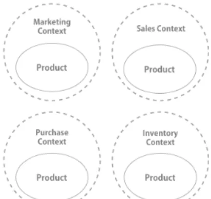
Step 4: Identify Bounded Contexts
Input Data: Diagram with Identified Subdomains Output Data Identified Bounded Contexts Description of Step 4: As illustrated in Figure 10 with the concept of Bounded Context, it is possible to set limits to a specific domain according to business intentions (Marketing, Sales, Purchase and Stock).
As domains and subdomains are identified and filled in the diagram, it is important to classify the essential functionalities from business and their existing relationships. At this stage, no concern should relate to implementation details. The focus is still on the domain knowledge.
Step 5: Build a Context Map
Input Data: Identified Bounded Contexts Output Data: Context Map
Description of Step 5: Once the Bounded Con-texts Mappingis done, the next step is to build a Con-text Map. The goals of this map is to make explicit the understanding of contexts and relationships between them. As well as the mapping of the Bounded Con-texts, the Context Map also needs to have a continuous process of improvement, so that the information of the Bounded Contextsand consequently the Context Map is improved.
In this stage of the migration it is possible to iden-tify, based on the tactical modeling of DDD, possi-ble candidates for entities, objects of value, services, among others.
The main focus of the first and second phases is the extraction of knowledge from the domain, iden-tifying the main functionalities and responsibilities in view of establishing coherent and validated limits
ba-sed on the system’s business rules.
6.4
Phase 3: Target Software
Architecture
The focus of this phase is on the decision and imple-mentation of the architecture. The first step of this phase is to decide whether the system architecture will be migrated to a microservice architecture. This is a decision that is up to the development team, who from the defined Context Map, can assess the comple-xity of the system, and whether there really is a need to migrate to a microservice-based architecture.
As described in the pilot study, it was noticed during Context Map analysis that the system had only three contexts: Identity Context, OfferContext and TicketContext. Because it is a simple system with a reduced number of contexts, it was decided to maintain the monolithic architecture, in view of the progress achieved in the modularization through the application of DDD concepts. One of the reasons for choosing not to migrate to a microservice architecture was to avoid increasing the system’s complexity, which would be a consequence of implementing to this architecture. Therefore, the number of contexts is a factor to be taken into account during this decision making. However, we do not go as far as to set a threshold value for a minimum number of contexts. Step 6: Migrate for Microservices Architecture
Input Data: System with Evolved Monolithic Ar-chitecture
Output Data: System with Microservices Archi-tecture
Description: deciding to migrate to a microser-vice architecture entails initiating a series of actions. First, note that in a scenario of a large application in a complex domain, it is very common to observe many contexts. Deciding on which context to start carrying out the migration is not a trivial task. An effective strategy is to select contexts that have no or few re-lationships. The number of bugs associated with a particular context may also be a factor.
For each Bounded Context a directory must be cre-ated, within each of the directories, three new direc-tories must be added, one for each layer: Domain, Application, Infrastructure. They must contain the necessary source code for the Bounded Context to work. It is essential to consider the domain models and their invariants and recognize Entities, Value Ob-ject’sand also Aggregates. The source code must be maintained in these directories as described in the se-quence. The Application directory should contain all application services and command handlers.
The Domain directory contains classes with exis-ting tactical patterns in DDD as: Entity, Value Object, Domain Event, Repository and Factory. The Infrastructure directory should provide the technical resources for other parts of the application, isolating all domain logic from the details of the in-frastructure layer.
The infrastructure layer should contain in detail the code for sending emails, sending messages, sto-ring information in the database, processing HTTP re-quests, and make requests to other servers. Any struc-ture and library related to the external world, such as network and file systems, must be used or called at the infrastructure layer.
The directory structure of a Bounded Context should be organized as follows:
+--src | +-- LegacySystem | +-- Context | +-- Application | +-- Domain | +-- Infrastructure +-- tests
In the scenario where the migration of architecture to microservices must take place, the Bounded Con-textswill play a key role in identifying and organizing the microservices.
It is essential that each service has its own structure allowing separate maintenance external repositories. This facilitates the development and implementation of adjustments that can be made separately, avoiding possible side effects (SPOF) other services. It is prudent to organize the contexts in well-defined layers, because this way allows us to express the domain model and business logic, eliminating dependencies on infrastructure, user interface and application logic, concepts that often are mixed. Everything that is related to the domain model must be concentrated on a layer, isolating it from the top layers, such as the user interface layer, application layer, and infrastructure (Evans, 2004). Step 7: Run Unit and Integration Tests
Input Data: Migrated Bounded Context
Output Data: Migrated Bounded Context with Executed Tests
Description: As the Bounded Contexts are being migrated, it is recommended that automated testing be performed, initially unit testing. The intent is ensure that the implemented parts are working as expected.
These three phases make up the core minimum set to perform a migration. There is the possibility of in-cluding new steps in one or more of the three phases,
depending on the specific characteristics of the soft-ware system in question.
7
LESSONS LEARNED
As a result of the experience of the two-phase study previously reported, we highlight four key challenges faced during the migration. The first challenge is the identification of functionalities. It is not a trivial task, especially when considering large modules with scat-tered and tangled functionalities. The literature has already discussed this relevant issue in the migration process (Ossher and Tarr, 2002). The second chal-lenge comes from the need to define optimal bounda-ries among candidate features for microservices. The third challenge comes from the need to decide which will befeatures should be converted to microservices. The fourth challenge is related to the need to carefully analyze these potential candidate microservices with respect to their respective granularity and respective cohesion.
Previous published work already addressed the decomposition problemfor identifying modules, pac-kages, components, and "traditional"services, mainly by means of clustering techniques upon design arti-facts or source code. However, boundaries between modules defined using these approaches were flexible enough to allow the software to evolve into instan-ces of Big Ball of Mud (Coplien and Schmidt, 1995). Although the discussion in the literature regarding the value of cohesive services and the power of Bounded Contexts, it seems to a void in the guidance on how to identify these in practice (McLarty, ). The main issue is that those people trying to determine service boundaries are technologists looking for a technolo-gical solution. On the other hand, defining cohesive, capability-aligned service boundaries instead requires domain expertise. To overcome this difficulty, a mo-delling exercise should be carried out independently of the specific technology used (Silva et al., 2019).
We managed to derive multiple autonomous mi-croservices, each with its own database, by applying the strategies reported above. For communication between the microservices, we used HTTP communi-cation mechanisms as API Restful and also asynchro-nous communication with an EventBus implementa-tion, running RabbitMQ4. As shown in figure 7, each of the microservices now work with an independent relational database, except the Marketing service be-cause it is an auxiliary service. For this one, we chose to use an in-memory database (Silva et al., 2019).
8
CONCLUSIONS
It should be noted that migrating a legacy application rarely can be performed without significant effort. It is often entails hard and complex work. To the best of our knowledge, there are frameworks that can be used to support practitioners during the development (forward engineering) of microservice-based systems, such as Spring Cloud5and Hystrix6, just to name a few. However, none of them provides full support to the three migration phases. To contribute to filling this gap, this paper presents the lessons learned to support this kind of migration. We believe that the availabi-lity these lessons learned can support and encourage practitioners from the industry and academia to per-form them.
The lessons learned were based on our experience on the two-phase study reported in this paper. We also plan to conduct a survey with practitioners from the industry. Among other things, we wish to collect opi-nions their perceptions regarding the challenges that are faced during this type of migration, learn about the requirements and characteristics for suitable pro-cesses.
REFERENCES
Balalaie, A., Heydarnoori, A., and Jamshidi, P. (2016). Mi-croservices architecture enables devops: migration to a cloud-native architecture. IEEE Software, 33(3):42– 52.
Coplien, J. O. and Schmidt, D. C. (1995). Pattern langua-ges of program design. ACM Press/Addison-Wesley Publishing Co.
Dragoni, N., Giallorenzo, S., Lafuente, A. L., Mazzara, M., Montesi, F., Mustafin, R., and Safina, L. (2017). Mi-croservices: yesterday, today, and tomorrow. In Pre-sent and Ulterior Software Engineering, pages 195– 216. Springer.
Evans, E. (2004). Domain-driven design: tackling comple-xity in the heart of software. Addison-Wesley Profes-sional.
Gamma, E. (1995). Design patterns: elements of reusable object-oriented software. Pearson Education India. Kalske, M., Mäkitalo, N., and Mikkonen, T. (2017).
Chal-lenges when moving from monolith to microservice architecture. In Current Trends in Web Engineering, pages 32–47. Springer, Cham.
Leymann, F., Breitenbücher, U., Wagner, S., and Wettinger, J. (2016). Native cloud applications: Why monolithic virtualization is not their foundation. In Cloud Com-puting and Services Science, pages 16–40. Springer, Cham.
5http://projects.spring.io/spring-cloud/ 6https://github.com/Netflix/Hystrix
Martin, R. C. (2002). The single responsibility principle. The principles, patterns, and practices of Agile Soft-ware Development, 149:154.
McLarty, M. Designing a microservice system.
Millett, S. (2015). Patterns, Principles and Practices of Domain-Driven Design. John Wiley & Sons. Nadareishvili, I., Mitra, R., McLarty, M., and Amundsen,
M. (2016). Microservice Architecture: Aligning Prin-ciples, Practices, and Culture. "O’Reilly Media, Inc.". Newman, S. (2015). Building microservices: designing
fine-grained systems. "O’Reilly Media, Inc.". Ossher, H. and Tarr, P. (2002). Multi-dimensional
separa-tion of concerns and the hyperspace approach. In Soft-ware Architectures and Component Technology, pages 293–323. Springer.
Richardson, C. (2014a). Microservices: Decomposing ap-plications for deployability and scalability.
Richardson, C. (2014b). Pattern: Monolithic architecture. Posje´ceno, 15:2016.
Seaman, C. B. (1999). Qualitative methods in empirical studies of software engineering. IEEE Transactions on software engineering, 25(4):557–572.
Silva, H., Carneiro, G., and Monteiro, M. (2019). An expe-rience report from the migration of legacy software systems to microservice based architecture. In In-formation Technology-New Generations (ITNG 2019), pages 159–165. Springer.
Singleton, A. (2016). The economics of microservices. IEEE Cloud Computing, 3(5):16–20.
Taibi, D., Lenarduzzi, V., and Pahl, C. (2017). Processes, motivations, and issues for migrating to microservices architectures: An empirical investigation. IEEE Cloud Computing, 4(5):22–32.
Toffetti, G., Brunner, S., Blöchlinger, M., Spillner, J., and Bohnert, T. M. (2017). Self-managing cloud-native applications: Design, implementation, and experi-ence. Future Generation Computer Systems, 72:165– 179.
Wolff, E. (2016). Microservices: Flexible Software Archi-tecture. Addison-Wesley Professional.