Rute Martins de Almeida
Licenciatura em Ciências de Engenharia de Materiais
Hydroxyapatite Porous Structures for
Bone Tissue Engineering
Dissertação para obtenção do Grau de Mestre em Engenharia de Materiais
Orientador: Prof. Doutor João Paulo Miranda Ribeiro Borges, FCT-UNL
Co-orientador: Prof. Doutor Jorge Carvalho Silva, FCT-UNL
Co-orientador: Mestre Carlos Filipe Cidre João, FCT-UNL
Júri:
Presidente: Prof. Doutor João Pedro Botelho Veiga, FCT-UNL Arguente: Doutora Cláudia Marina Souto Ranito Lourenço, Medbone
Vogal: Prof. Doutor João Paulo Miranda Ribeiro Borges, FCT-UNL
Dezembro 2014
iii
Hydroxyapatite Porous Structures for Bone
Tissue Engineering
Copyright © - Todos os direitos reservados. Rute Martins de Almeida; Faculdade de Ciências e Tecnologia, Universidade Nova de Lisboa.
A Faculdade de Ciências e Tecnologia e a Universidade Nova de Lisboa têm o direito, perpétuo e sem limites geográficos, de arquivar e publicar esta dissertação através de exemplares impressos reproduzidos em papel ou de forma digital, ou por qualquer outro meio conhecido ou que venha a ser inventado, e de a divulgar através de repositórios científicos e de admitir a sua cópia e distribuição com objetivos educacionais ou de investigação, não comerciais, desde que seja dado crédito ao autor e editor
v
Agradecimentos
Gostaria de agradecer a todos aqueles que contribuíram de forma directa ou indirecta para a concretização desta dissertação:
Em primeiro lugar, gostaria de agradecer aos meus orientadores, Professor Doutor João Paulo Borges, Professor Doutor Jorge Silva e Mestre Carlos João pelos conhecimentos transmitidos, pela disponibilidade, entusiasmo e pelo acompanhamento durante todo o trabalho.
Ao Doutor João Canejo, à Andreia Lopes, à Paula Soares, à Ana Baptista e à Coro Echeverria, obrigada pela simpatia e total disponibilidade no apoio em laboratório.
Agradeço também às investigadoras Alexandra Gonçalves, Sónia Pereira e Ana Pimentel pela colaboração prestada na aquisição de vários resultados necessários para a realização desta dissertação.
Um agradecimento especial à Doutora Andreia Ruivo pela preciosa ajuda na última fase do trabalho.
À Teresa, à Pontes, ao Marreiros, ao Alex, à Joana, à Tânia e ao Francisco, obrigada pela boa disposição e por todo o apoio ao longo destes meses.
Quero também agradecer aos meus pais e avós pela preocupação e apoio durante todo este percurso.
vii
Resumo
Esta dissertação teve como objetivo o desenvolvimento de espumas porosas de hidroxiapatite (HA) baseadas em réplicas invertidas de cristais coloidais (ICC) para substituição óssea. Um ICC é uma estrutura tridimensional de elevada porosidade que apresenta uma rede interconectada de poros com elevada uniformidade de tamanhos. Este tipo de arquitetura possibilita uma proliferação celular homogénea e superiores propriedades mecânicas quando comparada com espumas de geometria não uniforme.
O cristal coloidal (CC) - o molde da espuma - foi criado por empacotamento de microesferas de poliestireno (270 μm) produzidas por microfluídica e posterior tratamento térmico.
O molde foi impregnado com um gel de hidroxiapatite produzido via sol-gel utilizando pentóxido de fósforo e nitrato de cálcio tetrahidratado como percursores de fósforo e cálcio, respectivamente. A espuma cerâmica foi obtida num único passo depois de um tratamento térmico a 1100oC que permitiu a solidificação do gel e a remoção do CC.
A análise por espetroscopia de infravermelho por transformada de Fourier (FTIR) e difração de raios-X (XRD) revelou uma hidroxiapatite carbonatada tipo A com presença de fosfatos tricálcicos. As propriedades mecânicas foram avaliadas por testes de compressão. A biocompatibilidade in vitro foi demonstrada através de testes de adesão e proliferação celular de osteoblastos.
Palavras-Chave: réplicas invertidas de cristais coloidais, hidroxiapatite, substituto ósseo, microfluídica.
ix
Abstract
This dissertation focuses on the production of hydroxyapatite (HA) inverse colloidal crystal (ICC) scaffolds for bone tissue engineering. An inverse colloidal crystal is a three dimensional porous structure that has highly uniform pore sizes and a fully interconnected pore network with high porosity. This kind of architecture provides a homogeneous cell proliferation and better mechanical properties when compared with the available scaffolds with non-uniform geometry. The colloidal crystal (CC) - the scaffold template - was created by self-assembly and subsequent annealing of polystyrene microspheres (270 μm) produced through a microfluidics based technique.
In order to fabricate the ceramic ICC scaffold, the template was impregnated with a hydroxyapatite gel produced by a sol-gel route. Phosphorus pentoxide and calcium nitrate tetrahydrate were used as sol precursors of phosphorus and calcium, respectively. The 3D final structure was obtained in a single step after thermal treatment at 1100oC, allowing gel transformation into a solid HA block and CC removal.
Scaffold analysis by Fourier-Transform Infrared Spectroscopy (FTIR) and X-ray diffraction (XRD) revealed a type A carbonated hydroxyapatite with traces of β-tricalcium phosphate. Mechanical properties were evaluated by compression tests. In vitro biocompatibility was demonstrated through cell adhesion and proliferation tests after human osteoblast cell seeding in the scaffolds.
xi
Table of Contents
AGRADECIMENTOS
VRESUMO
VIIA
BSTRACT IXLIST OF SYMBOLS AND ABBREVIATIONS
XVII1. BACKGROUND
1
2. INTRODUCTION
3
2.1. H
YDROXYAPATITE3
2.1.1. POROSITY OF HA CERAMICS
3
2.2. H
YDROXYAPATITE SCAFFOLDS:
PRODUCTION METHODS AND COMMERCIAL AVAILABILITY4
2.3. I
NVERSEC
OLLOIDALC
RYSTALS6
3. MATERIALS AND METHODS
9
3.1. H
YDROXYAPATITEP
RODUCTION9
3.2. I
NVERSEC
OLLOIDALC
RYSTALF
ABRICATION9
3.2.1. MICROSPHERES PRODUCTION
9
3.2.2. COLLOIDAL CRYSTAL TEMPLATE FABRICATION
10
3.2.3. HYDROXYAPATITE INVERSE COLLOIDAL CRYSTAL FABRICATION
10
3.3. C
HARACTERIZATION10
3.3.1. OPTICAL MICROSCOPY
10
3.3.2. TG-DSC
11
3.3.3. XRD
11
3.3.4. FTIR
11
3.3.5. SEM
11
3.3.6. MECHANICAL TESTS: COMPRESSION
11
3.3.7. CELL ADHESION AND PROLIFERATION TESTS
12
4. RESULTS AND DISCUSSION
13
4.1. CC
FABRICATION13
4.1.1. POLYSTYRENE MICROSPHERES
13
4.1.2. EFFECTS OF TIME AND ANNEALING TEMPERATURE ON CC TEMPLATE
15
4.2. H
YDROXYAPATITEG
EL16
4.2.1. AGITATION TIME
16
4.2.2. AGING TIME
17
4.2.3. BINDERS
17
4.3. ICC
19
4.3.1. THERMAL TREATMENT AND ICC STRUCTURE
19
4.3.2. XRD ANALYSIS
24
4.3.3. FTIR ANALYSIS
26
xii
4.3.5. BIOCOMPATIBILITY EVALUATION
29
5. CONCLUSIONS AND FUTURE PERSPECTIVES
31
6. BIBLIOGRAPHY
33
APPENDIX
37
A
PPENDIXA
39
xiii
List of Figures
FIGURE 2.1 - (A) Section and (B) surface of porous HA scaffold produced by polymer replication
method [15] ... 4
FIGURE 2.2 - (A) Resin mold produced by stereolithography and resulting (B) HA scaffold with controlled internal architecture [15] . ... 4
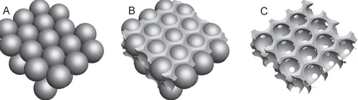
FIGURE 2.3 - ICC fabrication process: (A) Microspheres self-assembled in a hcp structure; (B) Microspheres infiltrated with scaffolding material; (C) Microspheres template removal (Adapted from [39]) ... 6
FIGURE 3.1 - Microfluidic device used for microsphere production ... 9
FIGURE 3.2 - Colloidal crystal mold with 32 cavities with 5,93 mm of diameter [46]. ... 10
FIGURE 4.1 - Influence of CP flow rate on microspheres diameter (CP concentration: 5 wt. %; DP concentration: 5 wt. %; DP flow rate: 3 mL/h). ... 14
FIGURE 4.2 - TG-DSC thermogram for polystyrene with amplification of the area corresponding to the 𝑇𝑔 peak. ... 15
FIGURE 4.3 - SEM image of colloidal crystal produced at 130oC. ... 16
FIGURE 4.4 - Aspect of HA gel aged for 24h after 5h stirring. ... 17
FIGURE 4.5- SEM image of HA ICC without binder. ... 18
FIGURE 4.6 - Microstructure of HA ICC wall (with PVP as binder) sintered at 600oC. ... 20
FIGURE 4.7 - The differences between coarsening and sintering [49]. ... 21
FIGURE 4.8 - Microstructure of HA ICC wall (with PVAc as binder) sintered at 600oC. ... 21
FIGURE 4.9 - SEM images of ICC’s sintered at 1100oC: (A) pores and (B) wall of ICC’s produced with PVAc as a binder; (C) pore and (D) wall of ICC produced with PVP as a binder... 22
FIGURE 4.10 - HA ICC's sintered (A) at 800 ºC and (B) at 1100 ºC. ... 22
FIGURE 4.11 - SEM image of ICC scaffold sintered at 1100oC. ... 23
FIGURE 4.12 - Diffractograms of HA ICC’s sintered at 600°C, 800°C and 1100°C. ... 24
FIGURE 4.13 - FTIR spectra of HA ICC’s sintered at 600°C, 800°C and 1100°C. ... 26
FIGURE 4.14 - Schematic compressive stress-strain curve for an elastic-brittle foam, showing the three regimes of linear elasticity, collapse and densification... 27
FIGURE 4.15 - Compressive stress-strain curves for HA ICC’s sintered at 600oC, 800oC and 1100oC. ... 28
FIGURE 4.16 - Corrected absorbance over an incubation period of 10 days ... 29
FIGURE 4.17 - Fluorescence microscopy image of human osteoblasts (Saos-2 cell line) ... 29
FIGURE 4.18 - SEM micrographs of ICC surface revealing the deposited layer of needle-like crystals with cauliflower morphology: (A) Pore and wall; (B) magnification of cauliflower structures. ... 30
FIGURE B.1 - TG-DSC thermogram for PVP ... 43
xv
List of Tables
TABLE 2.1 - Available methods to produce porous hydroxyapatite scaffolds. ... 5
TABLE 2.2 - Commercially available HA scaffolds for bone tissue replacement. ... 5
TABLE 4.1 - Influence of continuous phase flow rate on microspheres diameter. ... 13
TABLE 4.2 - HA crystallite sizes for sintering temperatures of 600°C, 800°C and 1100°C. ... 24
xvii
List of Symbols and Abbreviations
Abbreviation Designation
α -TCP α-Tricalcium phosphate
𝛽 Full width at half maximum of diffraction peak 𝛽-TCP β-Tricalcium phosphate θB Bragg angle 𝜆 X-ray wavelength CC Colloidal crystal CP Continuous phase DAPI 4',6-diamidino-2-phenylindole DMSO Dimethyl sulfoxide
DP Discontinuous phase
DSC Differential scanning calorimetry fcc Face-centered cubic
FTIR Fourier transform infrared spectroscopy HA Hydroxyapatite
hcp Hexagonal close-packed
𝐼300 Intensity of (300) diffraction peak of hydroxyapatite
ICC Inverse colloidal crystal PBS Phosphate buffered saline PCL Poly(caprolactone)
PLGA Poly(lactic-co-glycolic acid)
PS Polystyrene
PVA Poly(vinyl alcohol) PVAc Polyvinyl acetate PVP Polyvinylpyrrolidone rpm Revolutions per minute SEM Scanning electron microscopy
t Crystallite size
𝑇𝑔 Glass transition temperature
TG Thermogravimetry
𝑉112 300⁄ Intensity of the hollow between (112) and (300) diffraction peaks of hydroxyapatite
𝑋𝑐 Crystallinity degree
1
1. Background
The aim of this dissertation was the development of a hydroxyapatite porous scaffold for bone tissue engineering with an inverted colloidal crystal (ICC) architecture.
Hydroxyapatite has been used as scaffolding material for bone substitution. It has a chemical composition that resembles the mineral phase of human bone and consequently, an outstanding biocompatibility.
When designing a scaffold it would be desirable to reproduce bone’s properties in terms of composition and internal morphology as it should be able to support cell growth. It has been known that cells behavior is strongly affected by the scaffold properties, particularly by the constituent material’s nature, its pores interconnectivity, uniformity and size distribution.
Many types of hydroxyapatite scaffolds have been developed throughout the years but most of the fabrication techniques result in structures with random pore distributions. Consequently, the interconnectivity between pores is insufficient. This feature directly affects the nutrients, metabolites diffusion and bone regeneration. Although an increase in porosity degree could solve this problem, the scaffold’s mechanical strength would be compromised in a way that it wouldn’t be able to maintain structural stability until complete regeneration of the damaged bone tissue. Additionally, a random arrangement of pores doesn’t allow a good scaffold-to-scaffold reproducibility.
Inverted colloidal crystals emerged as a new type of three-dimensional scaffolds with controlled pore sizes, interconnectivity between pores and an ordered and uniform structure. The ability to control the architecture features allows obtaining scaffolds with better mechanical properties, which is important when designing an implant for a structural tissue like bone.
Combining such features with a bioactive material like hydroxyapatite may also enable an optimization of the scaffold‘s biological performance.
3
2. Introduction
2.1. Hydroxyapatite
Hydroxyapatite (HA) is a bioceramic that belongs to the apatite group and has the chemical formula Ca10(PO4)6(OH)2, with a Ca:P molar ratio of 1.67 [1].
Synthetic hydroxyapatite can be chemically obtained with outstanding similarity to biological apatites, which comprise the mineral phases of calcified tissues in the human body such as bone, dentin and enamel. The biological HA is usually calcium-deficient (Ca:P < 1.67) and is able to suffer a wide variety of substitutions in regular HA lattice points that may involve ions of Mg2+, Na+, K+,Sr2+, or Ba2+ for Ca2+, CO3 2 -, H 2PO4 -, HPO 4 2 -and SO 4 2 - for PO 4 3 -, and F--, Cl- and CO3 2 for OH- [2], [3].
Synthetic hydroxyapatite based ceramics have shown to be suitable for biomedical applications, such as bone repair, augmentation and substitution [4], [5]. They exhibit excellent biocompatibility with both hard and soft tissues, such as skin and muscle, as a result of similarity with bone’s inorganic phase. Moreover, HA is bioactive, and promotes osseointegration when directly implanted into bone [5], [6].
Despite these excellent features, this bioceramic shows limited mechanical properties, which are dependent on grain size and on the presence of impurities, whose influence is determinant when a highly porous sample is considered.
The biological behavior of HA ceramics depends on many factors, in particular, on their chemical and phase composition, microstructure, pore size, and porosity [7].
2.1.1. Porosity of HA ceramics
When developing porous HA for bone replacement, a special feature has to be addressed, like mimicking the macro and microporous architecture of bone, which consists of 55% - 70% interconnected porosity [3].
Porous HA allows a strong bonding to bone being the pores the providers of mechanical interlock leading to a firm material fixation. Bone tissue penetrates and grows into the pores, increasing strength of the HA implant [8], [9]. Also, pores dimension and morphology are crucial factors for an excellent osseointegraton. A minimum size of 100 m required to enable bone ingrowth into implants [10]. Many research groups have reported the optimum pore sizes for various kinds of cells or tissues: for example, 5–15 m for fibroblasts; ≈ 20 m for hepatocytes; 70–120 m for chondrocytes; 40–150 m for fibroblast binding; 60–150 m for vascular smooth muscle cell binding; 100–300 mm for bladder smooth muscle cell adhesion and ingrowth; 100– 400 m for bone regeneration, and 200–350 m for osteoconduction [11].
An essential requirement for porous implants is pores interconnectivity, which is essential to circulation and exchange of body fluids, ion diffusion, nutritional supply and osteoblast cell
4
penetration. In this context, closed pores do not participate in physiological events due to lack of accessibility by body fluids and cells. Other important requirement is implant surface roughness for cells attachment [8].
In summary, porosity, pore-size distribution, pore morphology and orientation, as well as the degree of pore interconnectivity strongly affect implant-tissue osseointegration.
2.2. Hydroxyapatite scaffolds: production methods and commercial availability
Various scaffold fabrication techniques have been developed in order to reproduce the structure and dynamics of bone tissue. The geometry of these scaffolds mainly depends on the process, and usually a poorly ordered structure is obtained with some closed porosity. Consequently, porosities often approach 95% to ensure a complete interconnectivity throughout the scaffold. Such high level of porosity present a dilemma in bone tissue engineering since it enhances interconnectivity but denies the scaffold of sufficient mechanical strength to ensure structural support until tissue regeneration is complete [12]. This issue becomes even more complex when considering brittle materials, such as hydroxyapatite.
A summary of advantages and disadvantages of some of the available methods to produce HA porous scaffolds is presented in table 2.1. For each technique, there is a wide range of possible features for the resultant scaffold, depending on the experimental conditions applied.
To overcome the randomness in the structures obtained by the majority of these techniques (example, Figure 2.1), methods like solid freeform fabrication have been developed. This kind of approach enables the production of 3D porous molds with desired properties such as porosity, interconnectivity and architecture. A hydroxyapatite positive replica of this mold can be therefore produced (Figure 2.2).
Although very promising, this method still carries some disadvantages (Table 2.1). As a solution for the limitations related to the proposed methods of HA scaffolds production, several studies have mentioned a well-defined scaffold with an high degree of interconnectivity called Inverse Colloidal Crystal (ICC) [11], [13], [14].
A B
Figure 2.1 - (A) Section and (B) surface of porous HA scaffold produced by polymer replication method [15].
Figure 2.2 - (A) Resin mold produced by stereolithography and resulting (B) HA scaffold with controlled internal architecture [15].
5
There are already some commercially available HA porous scaffolds for bone tissue replacement (Table 2.2).
Table 2.1 - Available methods to produce porous hydroxyapatite scaffolds.
Table 2.2 - Commercially available HA scaffolds for bone tissue replacement.
Method % Porosity Advantages Disadvantages Ref.
Polymer
replication 25 - 90
Complex shapes; high degree of interconnected porosity
Pore size distribution is not easily controllable; poor mechanical strength for
load-bearing applications
[15]–[18]
Gel casting of
foams 70 - 90
High mechanical strength; complex shapes
Poorly interconnected pores; non-uniform pore size
distribution
[19], [20]
Starch
consolidation 45 - 70
Simplicity of the process; possibility of using various mold materials to produce complex shapes; low-cost
processing equipment/materials needed
Low mechanical strengths for high pore volume fractions and
vice-versa
[21]
Microwave
processing 73 High porosities Small pore sizes [22] Slip casting > 50
Large pore sizes; controllable pore size distribution; complex
shapes
Slow process; poor control over
internal architecture [23]
Electrophoretic
deposition 20
Uniform and crack-free bulk porous scaffolds; interconnected porosity good
mechanical strength; no additives/binders needed
Wide range of pore sizes; high cost for large components; Low
porosity
[24]
Cold isostatic
pressing 70 Spherical porosity
Incomplete interconnectivity
between pores [25]
Freeze casting 40 - 65
Complex shapes; precise control over pore properties;
directional porosity; high compressive strength
Pore sizes usually small [26], [27]
Dual-phase
mixing 50 - 70 High mechanical strength
Incomplete interconnectivity between pores; non-uniform
pore size distribution
[28]
Solid freeform
fabrication –
Complex shapes and architectures; uniform and controllable pore
sizes
Time-consuming; computer-aided design; complex equipment; inadequate resolution (for small sizes)
[15], [29]
Company - Product (% HA - % β-TCP) Composition Porosity
(%)
Pore size
(m)
Compressive
strength (MPa) Ref.
Ceramed - NeoBone® 75 - 25 60 - 80 200 - 500 > 0.2 [30], [31] Ceramisys - ReproBone™ 60 - 40 83 200 - 800 > 1.5 [32], [33] Graftys - Graftys®BCP 60 - 40 70 > 100 > 10 [34] Kasios - TCH® 75 - 25 60 - 80 200 - 500 > 5 [35] Ldr - BF+® 60 - 40 60 - 80 200 - 500 N.A. [36] Medbone - adbone®BCP 75 - 25 80 300 - 500 1 - 2 [37]
6
2.3. Inverse Colloidal Crystals
An inverse colloidal crystal (ICC) is a three dimensional porous structure that has highly uniform pore sizes and a fully interconnected pore network with high porosity.
These properties enhance cell migration efficiency, diffusion of nutrients and metabolites, and a rapid and uniform distribution of soluble signaling molecules. A superior performance of the ICC’s has been confirmed when in comparison to scaffolds with non-uniform pores and structures [13].
From a manufacturing standpoint, the fabrication procedure of ICC scaffolds is simple, flexible and allows a great reproducibility among different batches (which is not always possible when using other scaffold production methods such as, polymer replication or gel casting).
First, microspheres with uniform size are assembled into an ordered structure; they tend to organize themselves (self-assembly) into thermodynamically stable forms, face-centered cubic (fcc) and hexagonal close-packed (hcp) structures(Figure 2.3 - A) [14]. The resulting structure is called colloidal crystal (CC).
In order to create a solid object, the microspheres are subjected to thermal annealing to induce necking between adjacent microspheres [39]. The major factor that influences this process is the crystallinity of the polymer used to produce the microspheres. Amorphous polymers, like polystyrene (PS), that soften above its glass transition temperature enable an easier production of the bridges between the microspheres allowing an easier production of the solid construct. This treatment is also responsible for the diameter of the interconnected pores. With the increase of the annealing temperature, the bridges between consecutive spheres increase as well, resulting in ICC scaffolds with interconnected pores with windows of higher diameters [40]. Then, a solution containing the scaffolding material is infiltrated into the lattice (Figure 2.3 - B). Any precursor solution capable of undergoing a liquid-to-solid transition may potentially be used as a scaffolding material. According to its properties, the material must be subjected to a specific treatment in order to promote solidification.
Figure 2.3 - ICC fabrication process: (A) Microspheres self-assembled in a hcp structure; (B) Microspheres infiltrated with scaffolding material; (C) Microspheres template removal (Adapted
7
Lastly, the lattice is selectively removed, leaving behind an inverse opal scaffold with uniform pore sizes and a long-range ordered structure defined by the microspheres solid structure (Figure 2.3 - C). Thanks to hcp geometry created by the microspheres self-assembly, each spherical cavity is connected with up to 12 nearest-neighbour cavities with two types of pores in different sizes. This type of geometry guarantees a maximum theoretical porosity of 74% [12]. Some scaffolds based on ICC structures aiming bone tissue repairing have already been reported. Cuddihy and Kotov [12] produced biodegradable poly(lactic-co-glycolic acid) (PLGA) ICC scaffolds through a soda lime microspheres template. This scaffolds demonstrated high mechanical properties (>50 MPa) and in vitro biocompatibility. Their studies indicated trends that larger pore sizes (100 – 330 μm) may increase cell and bone growth.
Nichols et al. [41] reported the development of an in vitro artificial bone marrow based on a scaffold with inverted colloidal crystal geometry mimicking the structural topology of actual bone marrow matrix. Scaffolds were manufactured composed of either silicate or hydrogel using a polystyrene colloidal crystal which produced cavities of 110 μm connected by 10 – 20 μm channels. The system allowed the growth and differentiation of cells.
Choi et al. [11] presented a technique for fabricating chitosan ICC’s in an array of poly(caprolactone) (PCL) microspheres of 147.7 m in average diameter. It resulted in structures with a nanofibrous texture on the walls surface promoting bone cells adhesion and proliferation. The tensile strength of the scaffolds was in the range of 30 to 60 kPa.
Takagi et al. [40] developed 𝛽-tricalcium phosphate (𝛽-TCP) ICC scaffolds by ceramic slip casting using polyethylene microspheres (ranging from 300 to 600 μm) assembled into an fcc lattice. The fabricated scaffolds showed an ordered pore structure with uniformly sized macropores and pore interconnection pathways that faithfully replicated the particles and their necks in the template, respectively.
With the purpose of recreating bone’s constitution (an organic and a mineral phase), a composite structure was produced: Choi, Zhang and their collaborators [42] presented ICC’s made of PLGA and HA using lattices of uniform gelatin microspheres as templates. Three formulations were examined: pure PLGA, PLGA/HA and apatite-coated PLGA/HA. With an average pore size of 213 μm, the scaffolds exhibited different compressive modulus: 196.2 kPa for the PLGA scaffolds, 1744.7 kPa for the PLGA/HA scaffolds, 1952.8 kPa for apatite-coated PLGA/HA scaffolds.
In this work the production of hydroxyapatite scaffolds with ICC geometry for bone tissue engineering will be explored.
9
3. Materials and Methods
3.1. Hydroxyapatite Production
Hydroxyapatite was produced using a sol-gel route. The experimental procedure was based on the works reported by Feng et al. [43] and Franco et al. [44]. Solutions containing calcium and phosphorous precursors in ethanol were mixed together in a Ca/P molar ratio of 1.67. A translucent gel with low viscosity was obtained after stirring this mixture for 5h and aging it for 24h, both at ambient temperature.
Posteriorly, the obtained HA gel was mixed with binders (a 25 wt.% poly(vinyl acetate) (PVAc) solution in acetone or a 25 wt.% polyvinylpyrrolidone (PVP) solution in ethanol) in a 98:2 weight ratio.
Reagents:
Absolute Ethanol: C2H6O, Fisher Scientific;
Acetone: C3H5O, Fisher Scientific;
Calcium Nitrate 4-hydrate: Ca(NO3)2.4H2O, Panreac;
Phosphorous Pentoxide: P2O5, Sigma-Aldrich;
Poly(vinyl acetate): (C4H6O2)n, Acros Organics, Mw ~ 100,000;
Polyvinylpyrrolidone: (C6H9NO)n, Sigma-Aldrich, Mw ~ 1,300,000.
3.2. Inverse Colloidal Crystal Fabrication
3.2.1. Microspheres Production
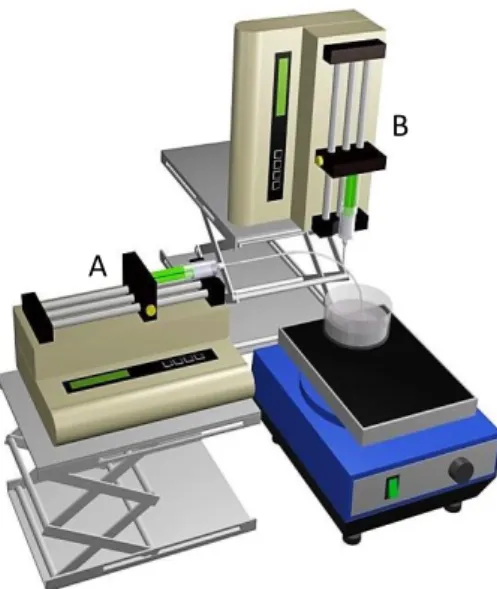
Uniform polystyrene spheres with average diameters of (270 ± 8) μm were produced using a microfluidic device as described in [45] (Figure 3.1).
Based on this technique, a 5 wt.% PS solution in dichloromethane contained on a syringe with a 25G needle was used as the discontinuous phase (DP). For the continuous phase (CP) an aqueous solution of 5 wt.% poly(vinyl alcohol) (PVA) contained on a syringe with a 18G needle was used.
The continuous phase polymer was chosen mainly due to its hydrophilic properties. Its combination with the hydrophobic PS phase enables the formation of an emulsion droplet.
The flow rates for the discontinuous and continuous phases were held at 3 and 20 mL/h, respectively.
Figure 3.1 - Microfluidic device used for microsphere production. A - continuous
phase; B - discontinuous phase [46]. A
10
The resulting microspheres were set in orbital agitation until solvent evaporation. Afterwards, they were washed with distilled water and size separated with appropriated sieves.
Reagents:
Dichloromethane: CH2Cl2, PA Fisher;
Polystyrene: [CH2CH(C6H5)]n, Aldrich, Mw ~ 350,000;
Poly(vinyl alcohol) : [-CH2CH(OH)-]n, Acros Organics, 95% hydrolyzed.
3.2.2. Colloidal Crystal Template Fabrication
The colloidal crystal template was created by self-assembly of the PS microspheres (into an hcp structure) in a cylindrical mold (Figure 3.2) under orbital agitation. Subsequently, the microspheres were heated at 130oC for 4 hours to promote annealing between adjacent microspheres. A solid structure was obtained after mold removal.
Figure 3.2 - Colloidal crystal mold with 32 cavities with 5,93 mm of diameter [46].
3.2.3. Hydroxyapatite Inverse Colloidal Crystal Fabrication
The obtained CC was infiltrated with the HA + binder gel mixture (§ 3.1), by introducing the sample into this solution and then promoting its penetration under vacuum. After being removed from solution, excess gel was cleaned from CC’s exterior walls.
The impregnated template was placed in a muffle oven (Select-Horn Electric Muffle Furnace) and held at 75ºC for 20h. The temperature was then increased to 450ºC at a rate of 2ºC/min and held for 2h. The previous heating rate was maintained followed by a 2h level at 550ºC. Lastly the structure was put at 1100ºC for 2h to sinterize, with a heating rate of 10ºC/min.
3.3. Characterization
3.3.1. Optical Microscopy
Microspheres diameters were measured with an optical microscope (Olympus Microscope Digital Camera DP73). This measurement was performed in 100 random samples of each production lot.
11 (1) t = 0.9 𝜆 𝛽 cos θB, [𝑛𝑚] (2) 3.3.2. TG-DSC
Glass transition and fusion temperatures of PS, PVP and PVAc were evaluated by differential scanning calorimetry (DSC) and thermogravimetry (TG). This step had the purpose of evaluating the materials thermal compatibility to optimize the annealing temperature, sintering and degradation steps.
3.3.3. XRD
The phase composition and crystallinity of HA was analyzed by X-ray diffraction (XRD) using CuKα radiation generated at 45 kV and 40 mA, in the range of 20°<2θ<60°, in a X’Pert PRO (PANAlytical) X-ray diffractometer. The obtained peaks were compared with JCPDS cards: #09-0169, #09-0348, #09-0432, e #37-1497. Crystallite sizes (t) were calculated from X-ray diffraction patterns using the Scherrer formula [47]:
𝜆 – X-ray wavelength; 𝛽 – full width at half maximum of diffraction peak; θB – Bragg angle.
The crystallinity degree (𝑋𝑐), corresponding to the fraction of crystalline phase present in the
examined samples was evaluated by the following equation [48]:
𝐼300 – intensity of (300) diffraction peak; 𝑉112 300⁄ – intensity of the hollow between (112) and
(300) diffraction peaks of hydroxyapatite.
3.3.4. FTIR
Fourier-Transform Infrared Spectroscopy (FTIR) analysis was carried out to identify the functional groups of HA. A Thermo Scientific (model Nicolet 6700) spectrometer was used.
3.3.5. SEM
Morphological observations of PS CC’s and HA ICC’s were performed in a Zeiss (model DSM 962) scanning electron microscope (SEM). All samples were sputter-coated with gold before SEM observation.
3.3.6. Mechanical tests: Compression
Uniaxial mechanical properties of ICC’s were determined using a Rheometric Scientific (Minimat Firmware 3.1) with a 20 N load cell at a rate of 0.5 mm/min.
𝑋𝑐= 1 −
𝑉112 300⁄
12
3.3.7. Cell Adhesion and Proliferation Tests
Biocompatibility of HA ICC’s was evaluated through cell adhesion and proliferation studies. In this work human osteoblasts from Saos-2 cellular line and a solution of McCoy’s 5A Medium (Sigma-Aldrich) supplemented with 10% of Fetal Bovine Serum (Gibco®) and 1% of Penicillin-Streptomycin(Gibco®) as cell culture medium were used. The chosen cells were seeded direct over with the material surface. The ICC’s used in the study were sterilized as described in Appendix A.1.
Firstly, the osteoblasts were thawed (Appendix A.2) and its subculture was prepared (Appendix A.3).
The ICC’s were placed in a multi well plate. Four different “types of wells” were prepared:
Medium Control well: containing medium without cells;
ICC Medium Control well: containing ICC’s and medium without cells;
Cell Control well: containing medium with cells;
Test well: containing ICC’s and medium with cells.
Cells were seeded in the last two types of wells at a concentration of 30 000 cells/well.
After 20h of incubation at 37oC (Sanyo CO2 incubator), the culture medium was removed from
the wells and in its place was added a solution of resazurin (0.2 mg/mL) and culture medium (10% V/V). After 2h of incubation the solution contained in the wells was transferred to a well microplate.
The fluid absorbance was measured at 570 and 600 nm in a microplate reader (Biotek ELx 800). The cells were cultured for 10 days. Absorbance readings were performed at days 1, 3, 6, 8 and 10 following the procedure described in the previous paragraph.
This step provides the necessary data to estimate cell adhesion and evaluate proliferation. Viable cells with active metabolism can reduce resazurin into the resorufin product which is pink and fluorescent and thus it changes the solution’s color. This color change can be detected using absorbance measurements. The corrected absorbance is proportional to the number of living cells and corresponds to the cells metabolic activity. Damaged and nonviable cells have lower metabolic activity and thus generate less resorufin than healthy cells. A more detailed protocol is described in Appendix A.4.
After the 10 days the cells were fixed with paraformaldehyde (PFA) to the ICC samples. The fixed cells were stained with DAPI (4',6-diamidino-2-phenylindole) so it was possible to observe them using fluorescence microscopy (Appendix A.5).
13
4. Results and Discussion
4.1. CC fabrication
4.1.1. Polystyrene Microspheres
4.1.1.1. Tuning of microspheres diameter
The diameter of the produced microspheres can be tuned mainly by changing the flow rate of each phase or the polymer concentration of the discontinuous phase. In this work, the DP corresponds to a polystyrene solution and the CP corresponds to a PVA solution (§ 3.2.1). As previously mentioned, it is required a minimum scaffold pore size of 100 m to enable bone ingrowth. It is also known that osteoblasts are about 10-30 m in size. Usually, the ICC’s windows diameter corresponds to about a third or quarter of the pores diameter (depending on the annealing conditions), so, in order to avoid windows blockage by cells and enable cell diffusion throughout the scaffold these facts should be taken into consideration.
Therefore, the effects of polymer concentration and flow rate were studied to try to achieve a microsphere diameter in the range of 200-300 m. Joana Vasconcelos work [46] was followed for some guidelines regarding flow rates and solutions concentration values. The effect of the flow rate on the average diameter was explored by holding the flow rate of the DP constant and varying the CP flow rate.
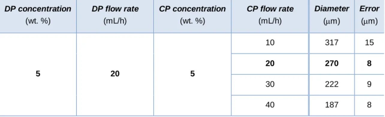
The following table contains all the variations imposed to CP flow rate, as well as the resultant microspheres diameter.
Table 4.1 - Influence of continuous phase flow rate on microspheres diameter.
DP concentration (wt. %) DP flow rate (mL/h) CP concentration (wt. %) CP flow rate (mL/h) Diameter (m) Error (m) 5 20 5 10 317 15 20 270 8 30 222 9 40 187 8
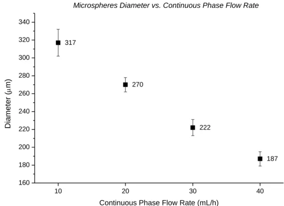
As expressed by Choi et al. [45] an increase in flow rate for the CP resulted in a reduction in microsphere diameter due to the increase in the shear stress imposed on the DP droplet (Figure 4.1).
14 10 20 30 40 160 180 200 220 240 260 280 300 320 340 317 270 222 187 Dia me ter ( m)
Continuous Phase Flow Rate (mL/h)
Microspheres Diameter vs. Continuous Phase Flow Rate
Figure 4.1 - Influence of CP flow rate on microspheres diameter (CP concentration: 5 wt. %; DP concentration: 5 wt. %; DP flow rate: 3 mL/h).
The chosen flow rates were: 20 ml/h for the continuous phase (PVA) and 3 mL/h for the discontinuous phase (PS). This conjugation generated microspheres with an average diameter of (270 ± 8) μm.
The resultant PS microspheres presented a negligible amount of defects, a uniform size distribution and spherical symmetry.
4.1.1.2. Effect of temperature on Polystyrene
Since the PS microspheres had to be subjected to several thermal conditions - the CC’s annealing and degradation during ICC’s production - it was necessary to analyze this polymer thermal behavior. A TG-DSC analysis was used to obtain the required data. The corresponding thermogram is shown in Figure 4.2.
Being an amorphous polymer, it doesn’t have a specific melting point; instead, it softens gradually as the temperature rises from the glass transition temperature, 𝑇𝑔 - above this
temperature, there’s an increased freedom of movement of local "segments" within the polymer chain. The 𝑇𝑔 was observed at 97.2ºC (it corresponds to the first peak midpoint temperature in
15 0 100 200 300 400 500 600 700 0 20 40 60 80 100 307C 415C 470C Temperature (C) TG (% ) exo 490C -6 -4 -2 0 2 4 D S C ( mW/ mg) Polystyrene TG-DSC
Figure 4.2 - TG-DSC thermogram for polystyrene with amplification of the area corresponding to the 𝑻𝒈 peak.
At about 307ºC the PS starts to degrade (there is a significant mass loss as seen in the figure above). The degradation is complete past the last endothermic peak, which corresponds to the degradation temperature. At this point, individual bonds between atoms start to break as the vibrations become more and more fierce until eventually, individual polymer molecules decompose into their components.
Based on the results, the annealing of the CC template should be done between 97.2ºC and 307ºC, knowing that higher annealing temperatures can cause a wider spread of the microspheres template material.
Also, in the ICC production process, the temperature must exceed the PS degradation temperature in order to create a porous structure by elimination of the polymer.
4.1.2. Effects of time and annealing temperature on CC template
Considering that PS begins to soften after approximately 97.2oC, a range of annealing temperatures (110-140oC) was selected to produce cohesive CC’s with complete interconnectivity between adjacent microspheres.
The upper limit of the temperature range was chosen so that microspheres were not excessively melted, which would inhibit the HA gel infiltration in the spaces between microspheres. Also, it could result in ICC’s with non-spherical porosity and excessive windows diameters. These facts would compromise the final product stability.
16
Below 125oC, the edges of CC’s crumbled when removed from the mold; at lower temperatures the annealing was insufficient to provide enough structural integrity for handling. Thereby, higher temperatures were explored.
The temperature that allowed the production of CC’s with the best characteristics was 130o
C. Annealing time also affects the CC’s features. It is known that for the same annealing temperature, a longer thermal treatment will result in ICC’s with wider windows. Therefore, a compromise between time and temperature was made.
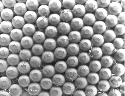
The annealing time was varied between 4 and 5.30h for the temperatures mentioned above. The chosen time for CC´s production was 4h for an annealing temperature of 130oC, resulting in cohesive CC’s with interconnected microspheres and enough open spaces for ICC’s material infiltration (Figure 4.3).
Some irregularities were observed in the CC template as a result of dispersion of microspheres diameter which resulted in uneven necking in some scaffold areas.
Figure 4.3 - SEM image of colloidal crystal produced at 130oC.
4.2. Hydroxyapatite Gel
4.2.1. Agitation Time
The agitation time of HA sol was varied to obtain a gel with adequate viscosity capable of being effectively impregnated into the CC’s.
A gel with high viscosity wouldn’t allow its efficient infiltration into the colloidal crystal, leaving gaps along the structure without any material. On the other hand, a gel with high fluidity would flow through the microspheres template resulting in a structure with insufficient material on the walls. Both conditions would result in fragile and unstable ICC’s.
17
A balance between these opposite extremes was found by varying the agitation time of HA sol until a gel with low viscosity was obtained. The attempted agitation times varied from 4 to 24 hours at 60 rpm (ambient temperature).
The viscosity of the resulting gel increased with agitation time becoming whiter each time. The sol agitation promotes the formation of a three dimensional network by aggregation of separate particles (transformation into a gel phase - gelation) and therefore the solution viscosity rises. However, the continuous stirring begins, at one point, to break this network apart. Accordingly, it can be said that the extended gel agitation slows or inhibits the complete gelation.
The gel with the most suitable viscosity was achieved after stirring for about 5 hours at ambient temperature (Figure 4.4).
4.2.2. Aging time
As part of the experimental process, HA ICC’s produced from aged and not aged gels were compared:
ICC’s produced from non-aged gelsThe resulting ICC’s were very brittle. Probably, the gel had no time to properly form a cohesive three dimensional network.
ICC’s produced from aged gelsBy the end of the aging process (24 hours at ambient temperature), the gel had a substantially higher viscosity (the gel agitation time was adjusted so to maintain a viscosity suitable for CC’s infiltration). Aging the gel before drying and sintering helped to strengthen the network and as a result the final product had higher structural integrity. This step was included in the production process of HA ICC’s, since it significantly improved the mechanical performance of the end product.
4.2.3. Binders
The HA/binder weight ratio was varied between 95:5, 97:3 and 98:2. Solution viscosity increased with higher amounts of binder. Since the microstructural differences were not significant, it was chosen to use the least amount of binder.
Without the addition of a binder the resultant structure was very brittle becoming hard to handle without breaking. The absence of binder resulted in ICC walls with a large amount of surface defects, from which cracks would originate and propagate (Figure 4.5). Consequently, they presented poor mechanical strength.
Figure 4.4 - Aspect of HA gel aged for 24h after5h stirring.
18
Figure 4.5- SEM image of HA ICC without binder.
The binder was used to hold together the ceramic structure after HA gel drying. Two binders were tested - PVP and PVAc. The introduction of a binder reduced the amount of surface defects on ICC walls. Still, some minimal defects remained. Both binders allowed the production of a more consistent ICC with the desired geometry (when compared with an ICC with no binder).
A better evaluation between the binders was made through comparison of ICC’s mechanical tests results and SEM micrographs. Their influence is better described in the chapters 4.3.1 and 4.3.4.
19
4.3. ICC
4.3.1. Thermal treatment and ICC structure
A thermal treatment composed by multiple stages was used to turn a CC into an ICC (a stage stands for a time period in which a certain temperature was held). The used stages are described below.
In the first attempts Stage 3 wasn’t included in the thermal treatment and the sintering temperature was equal or below 800ºC. Several problems remained cycle after cycle, so the sintering temperature was increased to 1100ºC and Stage 3 was added to the heating schedule. The following Stages constitute the final thermal treatment used for HA ICC’s production:
Stage 1: 75ºC - 20h (heating rate: 1ºC/min)
At the first hold temperature there is the loss of the solvent and physically adsorbed water - this is the gel drying stage. It was held for a long time period to ensure complete solvent loss. The heat-up rate from ambient temperature was slow to prevent bloating from evaporation that could originate cracks in the structure. At this stage the CC’s were able to
maintain its solid structure as the HA gel mixture dried.
Stage 2: 450ºC - 2h (heating rate: 2ºC/min)
The next stage is much above PS glass transition temperature (§ 4.1.1.3), so the CC’s begin to soften during the heating phase. From this point on, the PS is gradually being degraded. The binders that are used for body strength when the HA gel is dry must be burned out before sintering because they would decompose in an uncontrolled manner at sintering temperatures, releasing a large amount of gas at high pressure that would cause the structure to crack. Also, the ICC shape could be lost.
As the heating phase is taking place, PVP reaches its fusion temperature (~ 142ºC) and at the plateau temperature the polymer loss approximately 91 % of its mass (Appendix B.1). During this stage, PVAc is above its glass transition and had a mass loss of 71% (Appendix B.2).
Above 250ºC, pyrolysis of the dried gel molecular network begins. Pyrolysis creates tiny “holes” in the skeletal network that contribute to the pore volume and significantly increase the surface area because there is no associated shrinkage. The volatilization of the decomposition products of ligand groups is responsible for a weight loss [49], [50]. At the hold temperature the pyrolysis of organics is complete and HA crystallization begins.
Due to all these events, a low heating rate was kept to ensure that ICC’s internal shape was not destroyed.
20
Stage 3: 550ºC - 2h (heating rate: 2ºC/min)
This step ensured polystyrene template’s complete degradation. All the definitive cavities in the ICC structure were created.
By this stage PVP have undergone thermal decomposition and burned out. After binder burnout, the ICC is a porous structure composed by an assembly of ceramic particles. At this stage, PVAc is still suffering thermal degradation.
Further HA crystallization may have occurred.
Stage 4: 600ºC, 800ºC, 1100ºC - 2h (heating rate: 10ºC/min)
The last stage of the thermal treatment was for sintering, during which the majority of the densification and microstructure development took place. During the heat-up phase densification and microstructural changes may also have occurred.
The temperatures mentioned above for this stage were attempted in order to produce a cohesive HA ICC.
At the lower temperatures (600 and 800ºC) the densification was not effective. Coarsening of the ICC’s walls microstructure led to the formation of voids (Figure 4.6). When coarsening happens, the density does not increase even though the pores change shape. Thus, the particles were very loose and the structure was crumbly. The ICC walls exhibited microporosity and some roughness on the surface.
Figure 4.6 - Microstructure of HA ICC wall (with PVP as binder) sintered at 600oC.
If the interparticle separation distance remains the same, coarsening takes place. If the interparticle separation distance decreases, sintering takes place. Only sintering leads to an increase in density, which is referred to as densification (Figure 4.7) [49].
21 Figure 4.7 - The differences between coarsening and sintering [49].
The previous event is only valid at both sintering temperatures for ICC’s produced with PVP as a binder. At 600oC, PVAc isn’t fully degraded so these events were not observed. Since it’s a thermoplastic polymer, the remaining binder returned to solid state upon cooling which resulted in ICC with smoother walls. At 1100oC this binder has burned out.
Figure 4.8 - Microstructure of HA ICC wall (with PVAc as binder) sintered at 600oC.
At the higher temperature (1100ºC) densification took place (although incomplete) as confirmed by the shrinkage observed in the ICC’s after sintering. The final structure was much more stable than of those sintered at lower temperatures. The number of voids in ICC’s walls microstructure was reduced by the neck growth of the constituent grains (Figure 4.9).
The final ICC wall’s microstructure was affected by the used binder. Both “types” of ICC’s presented pores within the ceramic matrix since they were unable to complete densification. ICC’s walls with PVP as binder presented a higher amount of microporosity when compared with ICC’s made with PVAc. This could have been a result of the coarsening events that happened at the early stage of thermal treatment.
Sintering at a higher temperature should be enough to achieve the final stage of sintering,
coarsening
22
Figure 4.9 - SEM images of ICC’s sintered at 1100oC: (A) pores and (B) wall of ICC’s produced with PVAc as a binder; (C) pore and (D) wall of ICC produced with PVP as a binder.
The HA ICC’s sintered at 1100ºC turned white while the sintered below turned dark (Figure 4.10). It’s believed that above 800ºC, the residual organic groups were removed by decarbonation. Carbon is difficult to remove completely and the presence of carbon and other chemical residues in the final piece is normal [49].
Figure 4.10 - HA ICC's sintered (A) at 800 ºC and (B) at 1100 ºC.
After sinterization, the HA ICC’s were cooled down to room temperature and removed from the muffle oven.
A B
D
A B
23
The resulting ICC’s sintered at 1100o
C exhibited an interconnected structure with 80 vol.% porosity. The internal architecture was conserved from the sacrificial template with average pore sizes of (200 ± 2) m (Figure 4.11).
24
4.3.2. XRD Analysis
The diffractograms of HA ICC’s sintered at 600°C, 800°C and 1100°C are shown in Figure 4.12. The XRD patterns were compared with JCPDS cards.
20 25 30 35 40 45 50 55 60 o + + + + + + + + + -TCP + + + + + + + + + + + + + + + + + + HA O CaO 1100oC 800oC 600oC Angle (2) -TCP
Figure 4.12 - Diffractograms of HA ICC’s sintered at 600°C, 800°C and 1100°C.
Sintering temperature plays an important role on the formation of hydroxyapatite. As the sintering temperature is increased from 600oC to 1100oC, several of the HA peaks become more distinct and narrower which suggests an increase in the crystallinity degree (Figure 4.12). This affirmation is confirmed in Table 4.2, in which are presented the corresponding crystallite sizes determined by the Scherrer's formula (equation 1) and the crystallinity degree determined by equation 2.
Table 4.2 - HA crystallite sizesfor sintering temperatures of 600°C, 800°C and 1100°C.
Sintering Temperature (ºC) Crystallite Size (𝒏𝒎) Crystallinity Degree (%)
600ºC 25 ± 3 71
800ºC 47 ± 5 78
25
(3) The stoichiometry of HA is highly significant when is required thermal processing of the material. Using stoichiometric hydroxyapatite it should be possible to sinter, without phase purity problems, at temperatures up to 1300oC [1]. However, a minor misbalance in the calcium/phosphorus ratio (from the standard molar ratio of 1.67) can lead to the appearance of additional crystalline phases during heat treatment.
It can be seen that β-TCP (β-Ca3(PO4)2) appeared at all the sintering temperatures. Also, as the
temperature rises to 1100°C, a fraction of β-TCP phase is transformed in α-tricalcium phosphate (α-TCP – α-Ca3(PO4)2). The CaO phase was observed after sintering at 800
o
C.
These data indicates that HA can be decomposed into β-TCP/α-TCP and CaO as the sintering temperature is increased. The reaction is proposed as follows [51]:
Ca10(PO4)6(OH)2 3Ca3(PO4)2 + CaO + H2O
These calcium phosphates have different solubilities in vivo, being HA the least soluble [1]. A biphasic composition will influence the scaffold dissolution/bioresorption rate. Also, the scaffold’s microporous structure has an important role in this case due to the exhibited large surface area.
26
4.3.3. FTIR Analysis
The most characteristic chemical groups in an HA FTIR spectra are PO4
3 -, OH- and CO 3 2
-. The FTIR spectra of HA ICC’s sintered at different temperatures is shown in Figure 4.13.
4000 3500 1500 1000 500 OH -OH -600oC 800oC 1100oC PO 3-4 Wavenumber (cm-1) CO 2-3 PO 3-4 CO 2-3 PO 3-4 PO 3-4
Figure 4.13 - FTIR spectra of HA ICC’s sintered at 600°C, 800°C and 1100°C.
The first indication of the formation of HA is in the form of broad band centered at about 1000 – 1100 cm−1. The bands at 960 – 965 cm−1 and at 560 – 601 cm−1
correspond to the symmetric P-O stretching vibration of the PP-O4
3
ion [52].
CO32 -group forms a weak peak at 877 cm-1and a wider band between 1459 and 1546 cm-1 that
suggest the presence of a type A carbonated hydroxyapatite (hydroxyl ions are replaced with carbonate ions) [53].
The bands assigned to the stretching modes of hydroxyl groups in the HA (3571 cm−1 and 632 cm−1) can also be observed in the spectra [54].
27 4.3.4. Mechanical Properties
The compressive strength of ceramic porous scaffolds depends on various factors. Both the macrostructure (the arrangement of pores) and the microstructure (for instance, the presence of cracks within the structure walls), have a strong influence on the mechanical behavior of the ceramic porous material.
When a foam-like porous structure is compressed, the stress-strain curve usually shows three regions. At low stresses it shows linear elasticity followed by a long collapse plateau, ending with densification region in which the stress rises abruptly (Figure 4.14).
Figure 4.14 - Schematic compressive stress-strain curve for an elastic-brittle
foam, showing the three regimes of linear elasticity, collapse and densification (Adapted from [55]). 𝛔𝐜𝐫 ∗ - crushing stress; ∈𝐃 - densification strain.
On first compressive loading, the cell walls bend; the material exhibits a pseudo elastic behavior. The Young’s modulus corresponds to the initial slope of the stress-strain curve in this region. When a critical stress (σcr ∗ - crushing stress) is reached the cells begin to collapse
continuously by brittle fracture/crushing of their walls. This collapse will proceed under constant load to a relatively high strain level. Eventually, at high strains, the cells collapse sufficiently that opposing cell walls touch (or their broken fragments pack together) and further deformation compresses the cell wall material itself. This gives the final region of rapidly increasing stress labelled densification [55].
Figure 4.15 shows that the obtained stress-strain curves for the HA ICC’s are similar to the standard curve for brittle porous materials characterized by three distinct regions, although the elastic region is very small.
28 0,0 0,1 0,2 0,3 0,4 0,5 0,6 0,7 0,8 0 10 20 30 40 50 60 St re ss (kPa ) Strain 600oC 800oC 1100 oC
It can be seen that the mechanical strength of HA ICC’s to compression increases with the sintering temperature (Table 4.3). These results are in agreement with that exposed in chapter 4.3.1.
In Figure 4.15 and Table 4.3 are only presented the results for scaffolds produced with PVAc as a binder, since they showed better mechanical properties. For the scaffolds made with PVP the results for 600ºC and 800ºC were similar to the ones in the table below. In this case, the ICC’s sintered at 1100ºC exhibited a Young modulus of (398 ± 125) KPa.
Table 4.3 - Mechanical properties of HA ICC's sintered at 600oC, 800oC and 1100oC.
ICC [named after sintering temperature] Young Modulus (KPa)
600ºC 171 ± 12
800ºC 227 ± 34
1100ºC 747 ± 130
Figure 4.15 - Compressive stress-strain curves for HA ICC’s sintered at 600o
29 4.3.5. Biocompatibility Evaluation
In vitro tests demonstrated the nontoxic nature of the produced HA ICC scaffolds.
On the first day after seeding the cells showed 47% of adhesion to the ICC surface. The adhesion of osteoblast cells onto the ICC surface is a necessary step before cells proliferate and differentiate further. Throughout the 10 daysof culture it was observed an increase in the resazurin test absorbance values meaning a proportional increase of the number of cells (Figure 4.16). This shows that the samples were able to promote cellular proliferation.
1 3 5 7 9 0,05 0,10 0,15 0,20 0,25 0,30 0,35 Corr ec ted A bs orbanc e
Incubation Time (Days)
6 8 10
Figure 4.16 - Corrected absorbance over an incubation period of 10 days
Fluorescence microscopy confirmed that human osteoblasts were able to attach, proliferate and inhabit the scaffolds. The abundance of stained cells (the bright spots correspond to the cell’s nucleus) indicates a good viability (Figure 4.17). The seeded cells coated the ICC’s outer surface and appear to have infiltrated within the scaffold, yielding a uniform population throughout the structure.
Figure 4.17 - Fluorescence microscopy image of human osteoblasts (Saos-2 cell line) on HA ICC taken after 10 days of culture. The bright spots correspond to the cells on the
30
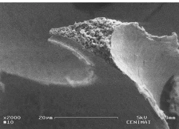
It was not possible to visualize the seeded osteoblasts through SEM. Instead, a layer of needle-like crystals over the ICC surface was revealed. The cauliflower morphology resulting from the assembling of these structures suggests them to be calcium phosphates (Figure 4.18). Biomineralization may have occurred on top of the attached cells as a consequence of calcium and phosphate ions release possibly resulting from HA dissolution and calcium secretion by cells. This reveals the bioactive nature of the produced scaffolds.
Figure 4.18 - SEM micrographs of ICC surface revealing the deposited layer of needle-like crystals with cauliflower morphology: (A) Pore and wall; (B) magnification of cauliflower structures.
A
31
5. Conclusions and Future Perspectives
Porous scaffolds with ICC geometry for application in bone tissue engineering were produced and characterized. The resulting scaffolds presented a biphasic composition of HA/β-TCP with macropore sizes of 200 m in diameter and a porosity of about 80 vol.%.
Templates with an hcp structure of polystyrene microspheres (270 m) were prepared by self- assembling and necking by heating at 130oC for 4 hours. It was verified that the necks between particles and future ICC windows could be easily tuned by changing the annealing time and temperature.
The scaffold material was prepared via a simple sol–gel method. It was found that a gel with suitable viscosity for colloidal crystal impregnation could be achieved after 5 hour stirring at ambient temperature. An aging time of 24 hours was added to strengthen the gel’s three-dimensional network.
The resulting HA gel was mixed with two different binders: PVP and PVAc. Their influence was compared after ICC sintering through mechanical testing and microstructure evaluation. PVAc allowed a better mechanical performance.
The HA gel was vacuum infiltrated into the particle-assembled template, followed by a heat treatment to burn out the polymer microspheres and sinter the HA. A range of sintering temperatures was tested (600-1100oC). It was verified that sintering at 800oC or below was not effective in promoting densification. Sintering at 1100oC was required for the ceramic particles to join and form a more continuous structure.
The fabricated scaffold showed an ordered pore structure that negatively replicated the microspheres and their necks in the colloidal crystal template. However, the interconnectivity between pores was not completely uniform throughout the scaffold. This could possibly be improved by using highly monosized microspheres which would allow even necking during CC production.
The scaffolds exhibited high crystallinity which increased with increasing of sintering temperature (71-98%). FTIR analysis revealed the presence of a type A HA.
The HA ICC’s sintered at 1100o
C demonstrated the best results in terms of mechanical properties. Nevertheless, they showed a low compressive strength around 747 kPa. This could be mainly due to incomplete densification of ICC walls that probably would be solved with increasing of the sintering temperature. Another possible reason is the existence of gaps in the scaffold material due to irregular infiltration of HA gel into the colloidal crystal.
In vitro biocompatibility with human osteoblasts was demonstrated. The cells were able to
attach and proliferate. Also, it was revealed an apatite forming ability with the appearance of needle-like cauliflower structures. Therefore it is expected that the scaffolds can provide a favorable environment for bone ingrowth.
32
The objectives of this work were partially achieved: a hydroxyapatite porous scaffold with inverse colloidal crystal geometry was produced but further work is needed to refine its mechanical properties (which are low when compared with commercially available HA scaffolds).
In the future several developments can be made to improve the HA ICC’s and the developed production method:
Sintering at an higher temperature (example, 1300oC) to improve the scaffold´s mechanical
properties by enabling complete densification;
Optimize the thermal treatment for ICC production in order to reduce production time (and
inherent costs) while preserving ICC structural integrity;
Study the sol gel system to explore the effect of gel agitation and aging time over the
scaffold’s microstructure and to optimize the gel viscosity for CC impregnation;
Further in vitro testing to evaluate the scaffolds solubility, behavior in biological environment
and the possible existence of calcium secretion by cells;
Integrate solid freeform fabrication based techniques with the ICC structures to create a

![Figure 3.2 - Colloidal crystal mold with 32 cavities with 5,93 mm of diameter [46].](https://thumb-eu.123doks.com/thumbv2/123dok_br/15134257.1011186/28.892.328.566.440.580/figure-colloidal-crystal-mold-cavities-mm-diameter.webp)