ISSN 1517-7076 artigo e-12191, 2018
Autor Responsável: Rogério Cattelan Antocheves de Lima Data de envio: 21/09/2017 Data de aceite: 02/03/2018
10.1590/S1517-707620180003.0525
Assess of hollow clay block masonry
wallets under high temperature
Rogério Cattelan Antocheves de Lima 1, Alessandro Onofre Rigão 1, Gihad Mohamad 1, Larissa Deglioumini Kirchhof 1,
Almir Barros da Silva Santos Neto1
1 Universidade Federal de Santa Maria - UFSM , Avenida Roraima, Centro de Tecnologia, Santa Maria, Rio Grande do
Sul, Brasil.
e-mail: [email protected], [email protected], [email protected], [email protected], [email protected], [email protected]
ABSTRACT
The main goal of this study was the behavioral assessment at high temperatures of masonry wallets built with different geometries of hollow clay blocks. In total, four type of structural wallets were erected; blocks of 15 x 20 x 30 cm nominal dimensions (width x height x length) and compressive strength of 7, 10, 15 and 18 MPa were built, employing laying mortar with compression resistance of 6, 8 ,10 and 12 MPa, respectively. The wallets were submitted to a constant temperature of 900°C, up to 4 hours, while heated gases permeabil-ity, thermal insulation and mechanical resistance were assessed. As conclusions, it was possible to observe that some wallets demonstrated the best thermal insulation performance, above 4 hours. Regarding the me-chanical resistance and the gas permeability, none of the wallets analyzed reached the flexural criteria estab-lished for the work.
Keywords: high temperature performance; clay blocks; masonry wallet.
1. INTRODUCTION
In Brazil, the structural masonry system, up to the 80s, was scarcely adopted; among other factors, it was due to the preferential use of reinforced concrete and the lack of tradition in considering walls for structural pur-poses. Nowadays, this system is well widespread, not only in the country, but also worldwide, due to several advantages as streamline execution, low losses index, execution flexibility and the need of integration with other several subsystems. In structural masonry, it is extremely important the knowledge of every single physical and mechanical peculiarities of its use, as well as technical characteristics on the performance against deadweight and wind actions, stability and safety in case of fire or elevated temperatures. Particularly, the safety in case of fire aims to minimize the risk for human lives and reduce property losses. The life risks include the user exposure to smoke or heated gases present in the environment, as well as the possible col-lapse of structural elements over the users or the rescue teams. On the other hand, the property loss represents the partial or total destruction of the construction, stored materials, documents and equipment, among the building finish and the neighboring constructions [1].
Studies revealed that most of the fire incidents related to civil construction occur in buildings, where the risk of death or severe injuries is elevated, being associated to the high temperatures reached during the incident and the dangerous levels of smoke and toxic fumes that propagate into the environment [2]. In view of the above, the majority of the current legislation on fire safety is based on fixed requirements to approve a construction element and to assure its functional stability during the heating process; the assessment is car-ried for a determined period of time arbitrarily chosen, according to the type of occupation, that will allow to vacate the building in safety. Hence, it is worth to emphasize the importance of this work in evaluating the performance of different types of structural clay blocks at high temperatures, in order to support the technical field through comparison criteria between the different cladding panels. It is important to remember that fire resistance is a crucial topic to be addressed in any engineering project, as in the majorities of buildings spe-cific structural and non-structural elements are technically selected to receive thermal barriers; these barriers will ensure fire resistance by preventing direct contact with the flame and/or the heated smoke, aiming to avoid fire propagation and the building colapse [3].
a specific fire resistance time. The ABNT NBR 9077:2001 [4] standard recommend that in order to obtain a fire resistance of 2 and 4 hours, the solid block wall needs to be 15 and 25 cm wide, respectively. Nonethe-less, in the country, one of the few code on fire prevention that present data based on laboratory tests is the São Paulo Fire Department Report nº 08 [5].
In Brazil, the test to determine fire resistance for structural constructive components is regulated by the NBR 5628 [6]standard, similar to the major international standards (ISO 834-1 [7]; 834-4 [8] and Euro-code 1 [9]). It consists in assess the construction element capacity to resist against the fire action for a certain period of time, keeping its structural safety, permeability and thermal insulation. Among other aspects, these norms define that the fire safety test has to be performed on a specimen with equivalent dimensions to the real scale element, and under the equivalent load that would be observed when in use. However, this proce-dure is difficult to execute, as the test equipment and machinery need to be of compatible dimension with the specimen tested and allow the service load application. NADNAI and O´GARA [10] relate that real structure tests, with large dimensions, are rare due to the elevated cost and dimension limitation of the furnaces estab-lished by regulation; consequently, test on part of the structure or computational simulation are normally real-ized.
Nowadays, only few national works can be found on the fire assessment of structural elements, as re-alized by KIMURA [11]; MARTINS [12]; COSTA and SILVA [13]. Internationally, the works of NGUYEN et al. [14-15]; NAHHAS et al. [16]; AL-SIBAHY and EDWARDS [17] studied the performance of masonry subjected to fire. However, these studies utilize conventional fence blocks, namely, without load bearing ca-pacity, and, with different geometries and resistance in respect to the masonry structural blocks found in Bra-zil. For this reason, the purpose of this study is to contribute in the assessment of the performance at high temperature of structural masonry components built with different geometries of clay blocks, verifying the permeability conditions, thermal insulation and mechanical resistance.
2. EXPERIMENTAL PROGRAM
2.1 Test procedures description
For the test procedures, it was considered as reference the recommendations NBR 5628 [6] standard, which recommend on how the element test against fire has to be carried. To evaluate the component performance at elevated temperatures, methodology procedures available at the Material and Civil Construction Lab (LMCC/UFSM) were adopted. During the tests, one of the surfaces of the panel was always exposed to a total heat of 900ºC, by means of an electrical furnace with programmable heating; the measurement of the temperature raising was made on the opposite face (the non-exposed one). Moreover, during the tests, it was always applied a constant axial load equivalent to the service load acting on the wall. The methodological procedures for the test executions are described as following:
- Coating of the superior wallet surface with structural grout for posterior service load application by a hydraulic jack;
- Positioning of auxiliary equipment (trails and metallic plates) for service load application on the panel, to be maintained constant for the duration of the test;
- Programming and triggering of the electrical furnace in order to heat the internal wallet surface, be-ing the increasbe-ing temperature rate of 10ºC/min until the value of 900ºC was reached;
- Constant temperature maintenance at 900ºC until one of the limiting conditions was reached, namely, fire permeability, thermal insulation and mechanical resistance;
- Once the temperature of 900ºC was reached, monitoring of the temperature increase on the external wallet surface every 30 minutes by a thermographic camera provided with an infra-red sensor;
- Observing and recording of longitudinal or transversal crack appearance during the test, as well as the impermeability loss due to flames and hot gases leakage;
- Test interruption after 4 hours of exposition to 900 ºC, in case none of the limiting conditions were reached before this time;
- Interruption of the service load application in case the wallet did not collapse during the heating pro-cess, followed by a natural cooling of 24 hours;
2.2 Performance criteria at high temperature
In order to evaluate the performance at elevated temperatures of different components of structural masonry, the recommendations found in the NBR 5628 [6] standard were followed.
The time in which at least one of these following conditions was reached during the test was estab-lished as failure criteria:
- Condition of fire permeability: it is considered impermeable the component that under the heat effect it does not suffer a failure sufficient to allow permeation of heated gases, from the exposed surface to the unexposed one, revealed by the ignition of a cotton pad;
- Condition for thermal insulation: it is considered satisfactory as thermal insulator the component that does not suffer a temperature raise above the initial temperature (room temperature), at the exposed surface, above 140 ºC in average or 180 ºC at any point;
- Condition for mechanical resistance: it is considered unused the component that, under load or heat effect, presents a lateral displacement or an excessive deformation that may cause specimen downfall or any other factor that may affect its mechanical resistance.
In the case that none of the limiting conditions is reached, the test is interrupted after 4 hour of speci-men exposition to 900°C.
2.3 Test execution
In total, four different wallets were fabricated with the dimensions of 75 cm (length) and 80 cm (height), namely, two block and half in length and four block in height.
The panels were erected with different block geometries, with nominal dimensions of 150 x 200 x 300
mm (width x height x length), named “A”, “B”,“C” and “D”. The masonry wallets were laid with industria
l-ized structural mortar, with constant joint thickness of 1.0 cm. Accordingly to the regional construction prac-tices, the external surface (in respect to heating) of the wallets was coated with a 2.0 cm thick finishing layer, over a layer of roughcast made by cement and sand in the proportions 1:3. On the internal surface, a finishing layer of 1.0 cm was applied directly onto the blocks, without roughcast. Table 1 collects the results of block physical characterizations, as water absorption for 24 hours (AA); initial water absorption index (AAI); gross and net area; average compression resistance and characteristic compression resistance estimated for the block.
Table 1: Blocks physical characteristics.
Block AA (%)
AAI (g/193.55 cm2
/min) Agross (cm2 ) Anet (cm2 )
fb average (MPa)
fbk extimate (MPa)
A 12.1 46 407.42 172.1 12.2 10.6
B 9.2 24 397.48 192.29 18.4 13.0
C 8.5 25 393.99 220.36 22.5 19.7
D 10.3 38 393.02 228.83 21,9 19,4
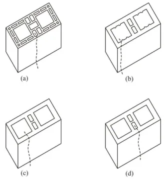
Figure 1 presents the clay structural unities named A, B, C, and D. Block A presents longitudinal and transversal hollow walls and a double central hollow septum, with smooth internal and external surfaces; type B block presents solid longitudinal and transversal walls, with a double central hollow septum having an equivalent thickness to the other block walls; block C has the same geometrical characteristics as block B, except for the grooves on the internal surfaces and cavities; at last, block D present the same geometry as block B and C, however, in this case, the external faces are grooved.
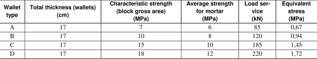
Table 2: Characteristics of the analyzed wallets.
Wallet type
Total thickness (wallets) (cm)
Characteristic strength (block gross area)
(MPa) Average strength for mortar (MPa) Load ser-vice (kN) Equivalent stress (MPa)
A 17 7 6 85 0,67
B 17 10 8 120 0,94
C 17 15 10 185 1,45
Table 2 presents the total thickness, the characteristic and average resistances for blocks and mortar, as well as the service load and the equivalent stress applied on each wallet, following the NBR 13279 [18] and NBR 15270 [19-21] standards. The total wallet thickness is the sum of the block thickness with the inter-nal and exterinter-nal coating layers.
(a) (b)
(c) (d)
Figure 1: Visual aspects of the four clay blocks used to build the masonry wallets.
(a) (b)
Figure 2: (a) General aspect of the furnace; (b) furnace opening for service load application.
The service load was applied by the means of a hydraulic jack with maximum 500 kN of loading ca-pacity, engaged by a manual pump with a pressure limit of 10,000 psi (68.9 MPa) and analogical display for load readings, as per Figure 3. The hydraulic jack was placed on the top portico beam and fixed by a metallic trail.
(a) (b)
Figure 3: (a) Hydraulic jack and (b) manual pump for service load application.
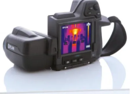
Figure 4: Thermographic camera with infra-red sensor (Source: http://www.contemp.com.br/produto/flir-t440/).
The wallets were positioned, together with the portico, in front of the furnace, while the auxiliary equipment for the aplication of uniform and constant load during the test were installed. The temperature was raised until 900°C were attained, with a heating rate of 10°C/min. The temperature was kept constant during the test until one of the failure criteria would be reached (permeability, insulation and mechanical resistance). The test was interrupted after 4 hours of exposition to 900°C, in case none of the limiting conditions present-ed itself. The reading of the thermal images was realizpresent-ed every 30 min, starting from the moment that the furnace indicated 900°C. In Table 3 the parameters used for the thermographic camera programming are pre-sented.
Table 3: Parameters employed for the thermographic camera programming.
Emissivity Reflected temperature
Room tem-perature
Relative humidity
Object distance
Wind (speed)
0.86 20ºC 20ºC 70% 3.0 m 0 m/s
3. RESULT ANALYSIS AND DISCUSSION
In the following sections, the test results will be presented related to each of the limiting conditions estab-lished for this work:
3.1 Permeability
All the wallets analyzed at high temperatures, with different block geometries, obtained a satisfactory per-formance for the permeability condition; that means, no extensive cracks that could allow the leakage of heated gases appeared on the unexposed surface, preventing the ignition of the cotton pad.
3.2 Thermal behavior
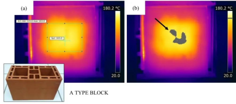
Figure 5: Block A wallet after 4h of exposition to 900ºC: (a) thermal image; (b) the isothermal region of temperatures
between 160ºC and 163ºC is presented in grey.
Regarding the component built with B block type, after 2 h and 30 minutes of exposition to 900°C, it was verified that the maximum temperature reached was 162.3°C (below the limiting condition of 180°C + room temperature) and that the average temperature recorded was 150.6°C, also below the limit of 160°C. These values indicated that after 2 h and 30 minute the wallet was still presenting a satisfactory thermal insu-lation. However, the temperature readings after 3hours of testing, revealed that one of the limiting condition for thermal insulation were exceeded: the external temperature reached 179.1°C, while the average
tempera-ture raised to 165.5°C (above 160°C), suggesting that the limiting criteria were overcome in 3 hours’ time.
Figure 6 shows the maximum temperature obtained by thermal imaging (a) and the isothermal curves for the temperature range between 160 and 179.1ºC (b).
Figure 6: Block B wallet after 3h of exposition to 900ºC: (a) thermal image; (b) the isothermal region of temperatures
between 160ºC and 179.1ºC is presented in grey.
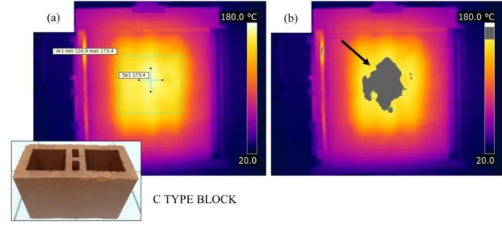
Figure 7: Block C wallet after 3h30min of exposition to 900ºC: (a) thermal image; (b) the isothermal range of temperatures between 160ºC and 173.4ºC is presented in grey.
The maximum temperatures on the external surface of the component made by D blocks, after 4 hours, reached 171.4°C, while the average temperature was 159.9°C. Once again, it was observed that both readings are below the established limit for thermal insulation. Figure 8 shows the maximum temperature obtained by thermal imaging (a) and the isothermal curves for the temperature range between 160 and 171.4 ºC (b).
According to the obtained results, it was possible to evaluate the different behaviors of structural ma-sonry components, erected with different geometry blocks, in relation to permeability and thermal insulation at elevated temperatures. These data are fundamental to project developers to foresee the structural element type to be used in critical regions of the building, as escape routes, stairs and elevator shafts, in order to as-sure structural safety and circulation during an accident as a fire.
Comparing the components, it was observed that the wallet A performed best for thermal insulation, due to the longitudinal and transversal walls being hollow, reducing thermal transmission as more air is trapped inside. The components built with block types B, C and D, had similar geometries, however, with different class of resistance. Observing the behaviors during the test, it is suggested that a higher resistance level for blocks and mortar could aid in increasing the time of thermal insulation.
Figure 8: Block D wallet after 4h of exposition to 900ºC: (a) thermal image; (b) the isothermal range of temperatures
between 160ºC and 171.4ºC is presented in grey.
3.3 Mechanical behavior
well as the thermal gradients through the wall thickness, related to the furnace heating rate. As it was intend-ed to evaluate the component accordingly to the current construction practices in (at) Santa Maria city, Brazil, and surroundings, another cause for the detachment of the coating could be the absence of roughcast between the block and the mortar, as one of the roughcast principal purposes is to increase adherence between the base and the plastering.
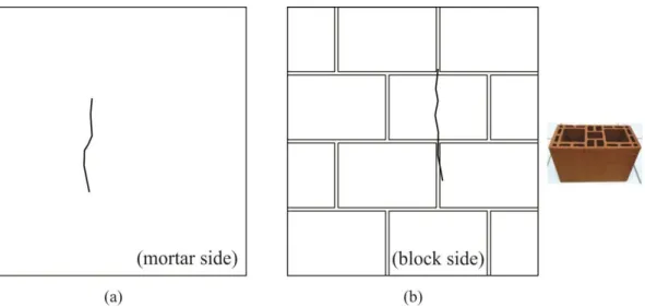
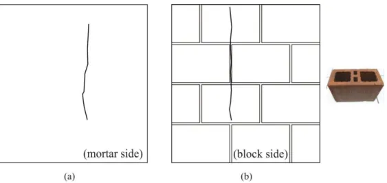
Regarding the panel with A block type, it is possible to observe in Figure 9 (a) that a vertical crack appeared in the grout of the external surface, propagating top-down in the panel, probably due to the thermal dilatation caused by heat. On the internal surface (directly exposed to heat), the mortar coating detached, ex-posing the same symmetrical vertical crack found on the external surface, which had propagated through the block and the laying mortar, as shown in Figure 9 (b).
Figure 9: External and internal cracking in the wallet built with A block type.
For the masonry structural component built with B block type, vertical cracks rose on the external sur-face coating; the cracks propagated from top to bottom, probably due to the thermal dilatation caused by heating, as depicted in Figure 10 (a) for the external surface and Figure 10 (b) for the internal surface in con-tact with the high temperatures.
Regarding the component built with the C block type, again, it was observed that the cracks were ver-ticals and propagated in the wallet top-down, as presented in Figure 11 (a). Moreover, as in Figure 11 (b), it was verified the presence of cracking and complete plastering detachment from the internal surface.
Figure 11: External and internal cracking in the wallet built with C block type.
The component built with the D block type, shown in Figure 12 (a), presented, once more, the appear-ance of a vertical crack on the plastering on the external surface, that propagated from top to bottom in the wallet. In Figure 12 (b), it can be visualized the image of the internal side of the wall, indicating the plaster-ing detachment.
Figure 12: External and internal cracking in the wallet built with D block type.
Figure 13: Position cracking in the different block types.
4. CONCLUSIONS
As conclusion of this work it can be stated that:
All the structural components presented a satisfactory behavior in respect to the “condition of perme
a-bility” to hot gases. During the test, none of the wallets presented cracks able to promote the ignition of a cotton pad.
In relation to the “thermal insulation condition”, the component built with B block type resulted to be the least satisfactory for this requirement. It is believed that this behavior is related to the lower compression resistance of the block, the applied loading level and the internal block geometry. On the other hand, it was observed that the blocks A and D presented the same level of thermal insulation, even if the compression resistance were the lowest and highest tested, respectively. It is believed that the internal geometry of block A could be the principal factor for this similar behavior, having longitudinal and transversal hollow walls and a double central hollow septum, offering higher resistance to thermal transmission for the formation of
sever-al cells “wsever-all-air-wall”. This fact became well understood when the thermal insulation for blocks B, C and D were compared, as all had solid longitudinal and transversal walls and a double central septum. In these blocks, the thermal transmission was directly proportional to the block compression resistance and the level of loading applied.
For the condition of “mechanical load capacity”, all the panels had appropriate behavior during the
tests; none of them showed displacement or excessive deformation, even when the loading was reapplied after 24 hours from the test.
In conclusion, it is possible to state that fire can cause degradation of the physical and thermomechan-ical properties of the materials that compose the building system. Fast heating might crate mechanthermomechan-ical capaci-ty losses, rigidicapaci-ty and cracking; in the case of structural masonry, the adhesion destruction between the block and the coating mortar might occur, as well as the progressive deterioration of the laying mortar. These changes are resulting from irreversible processes occurred during heating and the remaining time at elevated temperature, that can entail a reduction of the load capacity or even the premature collapse of the building.
5. BIBLIOGRAPHY
[1] ASSOCIAÇÃO BRASILEIRA DE NORMAS TÉCNICAS. NBR 14432. Exigências de resistência ao fogo de elementos construtivos de edificações - Procedimento. Rio de Janeiro, 2000.
[2] VARGAS, M.R, SILVA, V.P. Resistência ao fogo de estruturas de aço. 1ª Edição. Rio de Janeiro: Insti-tuto Brasileiro de Siderurgia – IBS / Centro Brasileiro da Construção em aço – CBCA, 2003.
[3] BUCHANAN, A.H. Structural design for fire safety. Chichester, John Wiley & Sons Ltda., 2002.
[4] ASSOCIAÇÃO BRASILEIRA DE NORMAS TÉCNICAS. NBR 9077. Saída de emergência em edifícios. Rio de Janeiro, 2001.
[5] POLÍCIA MILITAR DO ESTADO DE SÃO PAULO. Corpo de Bombeiros. In: Instrução Técnica nº 08: Resistência ao fogo dos elementos de construção. Secretaria de Estado dos Negócios da Segurança Pública, São Paulo, 2011.
[6] ASSOCIAÇÃO BRASILEIRA DE NORMAS TÉCNICAS. NBR 5628. Componentes construtivos estru-turais – Determinação da resistência ao fogo. Rio de Janeiro, 2001.
[7] INTERNATIONAL ORGANIZATION FOR STANDARDIZATION. ISO 834-1. Fire-resistance tests - element of building construction, part 1: general requirements. Geneva, 1999.
[8] INTERNATIONAL ORGANIZATION FOR STANDARDIZATION. ISO 834-4 – Fire-resistance tests - element of building construction, part 4: specific requirements for loadbearing vertical separating elements. Geneva, 2000.
[9] EUROPEAN COMMITTEE FOR STANDADIZATION. EUROCODE 1 – Actions on structures part 1-2: General Actions: Actions on structures exposed to fire. Brussels, 2002.
[10] NADNAI, A., O´GARA, M., “Compartment masonry walls in fire situations”. Fire Technology. Vol. 42, pp. 211-231, Jul., 2006.
[11] KIMURA, E.F.A., Análise termoestrutural de pilares de aço em situação de incêndio, Dissertação de M.Sc, USP/São Carlos, SP, Brasil, 2009.
[12] MARTINS M.M., Dimensionamento de estruturas de aço em situação de incêndio, Dissertação de M.Sc, UFMG/Belo Horizonte, MG, Brasil, 2000.
[13] COSTA C.N., SILVA V.P., Considerações sobre a segurança das estruturas de concreto em situação de incêndio. In: Seminário Internacional NUTAU'2004 Tecnologia e Desenvolvimento, 2004, São Paulo. NUTAU 2004.
[14] NGUYEN T.D., MEFTAH F., CHAMMAS R., MEBARKI A., “The behavior of masonry walls sub-jected to fire: Modelling and parametrical studies in case of hollow burnt-clay bricks”, Fire Safety Journal,v. 44, n. 4, pp.629-641, May., 2009.
[15] NGUYEN T.D. and, MEFTAH F., “Behavior of clay hollow-brick masonry walls during fire. Part 1: Experimental analysis”, Fire Safety Journal, v. 52, pp. 55-64, Aug. 2012.
[16] NAHHAS F.A., SAADA R.A., BONNET G., et al., “Resistance to fire of walls constituted by hollow blocks: Experimental and thermal modeling”, Applied Thermal Engineering, v. 27, n. 1, pp. 258- 267, Jan. 2007.
[17] AL-SIBAHY A. and, EDWARDS R., “Behaviour of masonry wallettes made from a new concrete for-mulation under combination of axial compression load and heat exposure: Experimental approach”, Engi-neering Structures, v. 48, pp. 193- 204, Mar. 2013.
[18] ASSOCIAÇÃO BRASILEIRA DE NORMAS TÉCNICAS. NBR 13279. Argamassa para assentamento e revestimento de paredes e tetos – Determinação da resistência à tração na flexão e à compressão. Rio de Janeiro, 2005.
[19] _______. NBR 15270. Componentes cerâmicos Parte 1: Blocos cerâmicos para alvenaria de vedação –
Terminologia e requisitos. Rio de Janeiro, 2005.
[20] _______. NBR 15270. Componentes cerâmicos Parte 2: Blocos cerâmicos para alvenaria estrutural –
Terminologia e requisitos. Rio de Janeiro, 2005.
![Table 2 presents the total thickness, the characteristic and average resistances for blocks and mortar, as well as the service load and the equivalent stress applied on each wallet, following the NBR 13279 [18]](https://thumb-eu.123doks.com/thumbv2/123dok_br/16316068.718833/4.892.185.731.219.553/presents-thickness-characteristic-average-resistances-service-equivalent-following.webp)