MAS-ML 2.0: Supporting the modelling of multi-agent systems with
different agent architectures
Enyo José Tavares Gonçalves
a,∗, Mariela I. Cortés
b, Gustavo Augusto Lima Campos
b,
Yrleyjander S. Lopes
b, Emmanuel S.S. Freire
b, Viviane Torres da Silva
c, Kleinner Silva Farias de
Oliveira
d, Marcos Antonio de Oliveira
eaUniversidade Federal do Ceará, Av. José de Freitas Queiroz, 5003 – Cedro CEP 63900-000, Quixadá, CE, Brazil bUniversidade Estadual do Ceará, Fortaleza, CE, Brazil
cIBM Research Brazil, Rio de Janeiro, RJ, Brazil
dUniversidade do Vale do Rio dos Sinos, São Leopoldo, RS, Brazil eUniversidade Federal do Ceará, Quixadá, CE, Brazil
a r t i c l e
i n f o
Article history:
Received 26 September 2014 Revised 16 April 2015 Accepted 4 June 2015 Available online 12 June 2015 Keywords:
Proactive and reactive agents Multi-agent system Modelling language
a b s t r a c t
Multi-agent systems (MAS) involve a wide variety of agents that interact with each other to achieve their goals. Usually each agent has a particular internal architecture defining its main structure that gives support to the interaction among the entities of MAS. Many modelling languages have been proposed in recent years to represent the internal architectures of such agents, for instance the UML profiles. In particular, we highlight MAS-ML, an MAS modelling language that performs a conservative extension of UML while incorporating agent-related concepts to represent proactive agents. However, such languages fail to support the modelling of the heterogeneous architectures that can be used to develop the agents of an MAS. Even worse, little has been done to provide tools to help the systematic design of agents. This paper, therefore, aims to extend the MAS-ML metamodel and evolve its tool to support the modelling of not only proactive agents but also several other architectures described in the literature.
© 2015 Elsevier Inc. All rights reserved.
1. Introduction
Nowadays, agent technology has been widely applied to solve a vast set of problems.Russell and Norvig (2003)define an agent as an entity that can perceive its environment through sensors and act in the environment through actuators. Unlike objects, agents are more complex entities with behavioural properties, such as (i) autonomy (i.e., they are able to execute without interacting with humans), and (ii) interaction (i.e., they are able to interact by sending and receiv-ing messages and not by explicit task invocation (Wagner, 2003). Multi-agent system (MAS) is the subarea of artificial intelligence that investigates the behaviour of a set of autonomous agents, aiming to resolve a problem that is beyond the capacity of a single agent (Jennings, 1996).
A simple agent can act based on reactive or proactive behaviour and can be classified according to its internal architecture that
de-∗ Corresponding author. Tel.: +55 88 3412 0919; fax: +55 88 3412 3348.
E-mail addresses: [email protected], [email protected] (E.J.T. Gonçalves), [email protected](M.I. Cortés),[email protected](G.A.L. Campos),yrley @larces.uece.br(Y.S. Lopes),[email protected](E.S.S. Freire),[email protected] (V.T. da Silva),[email protected](K.S.F. de Oliveira), [email protected] (M.A. de Oliveira).
termines distinct agency properties, attributes and mental compo-nents (Russell and Norvig, 2003).Russell and Norvig (2003)define four types of agents according to their internal architectures: Simple Reflex Agent, Model-Based Reflex Agent, Goal-based Agent and Utility-Based Agent. The internal architecture of an agent is selected according to the environment characteristics and to the subproblem that the agent will resolve. InWeiss (1999), environments are clas-sified as (i) fully observable or partially observable, depending of the degree of awareness; (ii) deterministic (foreseeable) or stochas-tic (unforeseeable), depending on the predictability of the environ-ment evolution; (iii) episodic (an action does not depend on previous actions) or sequential (the execution of an action depends on previ-ous actions); (iv) static (the environment does not change while the agent is reasoning) or dynamic (it changes while the agent is reason-ing); and (v) discrete (it has a finite quantity of states) or continuous (it has a continuous quantity of states). MAS may encompass multiple types of agents with different internal architectures (Weiss, 1999).
The agent-oriented development paradigm requires adequate techniques to explore its benefits and features in order to support the construction and maintenance of this type of software (Zambonelli et al., 2001). As it is the case with any new software engineer-ing paradigm, the successful and widespread deployment of MASs http://dx.doi.org/10.1016/j.jss.2015.06.008
requires modelling languages that explore the use of agent-related abstractions and promote the traceability from the design models to code. To reduce the risk when adopting a new technology it is convenient to present it as an incremental extension of known and trusted methods, and to provide explicit engineering tools that sup-port industry-accepted methods of technology deployment (Castro et al., 2006). A modelling language for a multi-agent system prefer-ably should be an incremental extension of a known and trusted modelling language. Since agents and objects coexist in MASs, the UML modelling language (Castro et al., 2006) can be used as a ba-sis for developing MAS modelling languages. The UML modelling lan-guage is a de facto standard for object-oriented modelling. UML is used both in industry and academia for modelling object-oriented systems. Nevertheless, in its original form UML provides insufficient support for modelling MASs.
There are several MAS modelling languages (Argente et al., 2009) that have extended UML to model agent-oriented characteristics. However, there is still a need for a modelling language capable of
mod-elling different internal agent architectures. The main goal of this paper
is to present a UML-based modelling language able to model the
inter-nal agent characteristics presented inRussell and Norvig (2003). In order to accomplish our goal, we have extended MAS-ML (multi-agent sys-tem modelling language) (Silva et al., 2008a), a modelling language that performs a conservative extension of UML based on the agent-oriented concepts defined in the conceptual framework TAO (Tam-ing Agents and Objects) (Silva and Lucena, 2004). MAS-ML and TAO were originally designed to support the modelling of only proactive agents that are goal-based entities guided by predefined plans. How-ever, not all MASs require proactive agents, as in the case of simu-lations for an ant colony (Dorigo and Stützle, 2004). Therefore, it is important to extend MAS-ML and also TAO to be able to model not only proactive agents but also reactive ones. Together with the exten-sion of MAS-ML and TAO we also felt the need to extend the MAS-ML
modelling environment.
We have chosen MAS-ML since it gives support to the modelling of (i) the main MAS entities: agents, organization and environments; (ii) the static and dynamic properties of a MAS; (iii) agent roles, what is important while defining agent societies; and (iv) proactive agents. Languages such as AUML (Agent Unified Modelling Language) (Odell et al., 2000; Guedes and Vicari, 2009) and AORML (Agent-Oriented Relationship Modelling Language) (Wagner, 2003; Wagner and Taveter, 2005) do not define (i) the environment as an abstrac-tion, so it is not possible for model agents able to move from one environment to another; and (ii) the properties of organizations are not described, so it is not possible to model agents from one orga-nization to other. One of the factors that influences the choice of the internal architecture is the type of environment in which the agent is inserted, so the environmental representation in diagrams of languages is desirable because once this is modelled, it is possible to explain its kind by textual notes, for example. For the organiza-tion, although not related to the choice of internal architecture, its representation is important from the point of view of coordination between agents. The ANote Modelling language (Choren and Lucena, 2005), for instance, does not support conventional objects used to model non-autonomous entities. In addition, in AML (Agent Mod-elling Language) (Cervenka, 2012), the communication relationships are modelled as a specialization of UML elements, which is not suitable for modelling agent communication.
In order to validate the extensions being proposed for MAS-ML 2.0, TAO and the modelling tool, a case study was performed in order to use our extensions to model the TAC-SCM system (Trading Agent Competition – Supply Chain Management) (Sadeh et al., 2003). Such a system simulates simultaneous auctions with consumers and sup-pliers of computers. Five agents implemented with different internal architectures were modelled by using MAS-ML 2.0 and other three modelling languages: original MAS-ML, AUML and AML. These
dif-ferent models allowed us to demonstrate the expressiveness of the proposed extensions over other approaches. MAS-ML 2.0 is able to model all four internal agent architectures while original MAS-ML, AUML and ML are able to model only the two simpler architectures.
The paper is structured as follows. The main internal architectures for agents, TAO and MAS-ML, are described inSection 2.Section 3 presents related works involving conceptual frameworks and mod-elling languages. The extension of TAO is described inSection 4, MAS-ML extension is detailed inSection 5and the MAS-ML tool is detailed inSection 6. InSection 7the modelling of the TAC-SCM (Trading Agent Competition – Supply Chain Management) (Sadeh et al., 2003) application is presented in order to illustrate the contribution of this work. Finally, conclusions and future works are discussed in Section 8.
2. Background
This section describes the main concepts needed to understand this work, including the concepts related to agent architectures, TAO conceptual framework and MAS-ML modelling language.
2.1. Agent architectures
The agent internal architectures can be categorized based on proactive and reactive foundations. In this context, four types of in-ternal agent architectures were defined byRussell and Norvig (2003). These architectures are detailed in the next sections.
2.1.1. Simple Reflex Agents
A Simple Reflex (or reactive) Agent (Russell and Norvig, 2003) is considered the simplest internal architecture. Condition-action rules are used to select the actions based on the current perception. These rules follow the form “if condition then action” and determine the action to be executed if the perception occurs. This architecture as-sumes that at any time the agent receives information from the en-vironment through sensors. These perceptions consist of the rep-resentation of state aspects that are used by the agent for making decisions. A subsystem is responsible for the decision-making, that is, responsible for processing the perception sequence and select-ing a sequence of actions from the set of possible actions for the agent. The agent performs the selected action upon an environment through actuators.
2.1.2. Model-Based Reflex Agents
The structure of this kind of agent is similar to the Simple Reflex Agent presented before since it deals with the information by using condition-action rules. In order to handle partially observable envi-ronments and to reach a more rational performance, the agent is also able to store its current state in an internal model.
According toWeiss (1999), Model-Based Reflex Agents select ac-tions by using the information in their internal states. A function called next function is introduced to map the perceptions and the cur-rent internal state into a new internal state used to select the next action. Such a state describes aspects of the world (called model) that cannot be seen in the current moment but were perceived earlier or have come out by inferences (Russell and Norvig, 2003).
2.1.3. Goal-Based Agents
Sometimes the knowledge about the current state of the environ-ment is not enough to determine the next action and additional infor-mation about desirable situations is required. Goal-Based Agents are Model-Based Agents that set a specific goal and select the actions that lead to that goal. This allows the agent to choose a goal state among multiple possibilities.
Planning activity is devoted to finding the sequence of actions that are able to achieve the agent’s goals (Russell and Norvig, 2003).
• Planning, which receives the problem and uses search and/or logic
approaches to find a sequence of actions to achieve a goal; and • Action, which is represented with its pre-conditions and
post-conditions.
2.1.4. Utility-Based Agents
Considering the existence of multiple goal states, it is possible to define a measure of how desirable a particular state is. In this case, aiming to optimize the agent performance, the utility function is re-sponsible for mapping a possible state (or group of states) to that measure, according to the current goals (Russell and Norvig, 2003). Thus, the utility function is incorporated into the architecture.
In addition, the Utility-Based Agent preserves the same elements as those of a Goal-Based Agent: next function, formulate goal function,
formulate problem function, planning and action.
2.1.5. Internal architectures choice
We chose the internal architectures of agents related byRussell and Norvig (2003)because (i) they are widely used in development of MAS, and (ii) it is not possible model them with the available syntax in MAS modelling languages.Russell and Norvig (2003)andWeiss (1999)have related the choice of the internal agent architecture to the characteristics of the environment.
The proactive behaviour is especially suited to environments with well-defined tasks, that is, deterministic, observable and static envi-ronments. Designing proactive agents in stochastic and partially ob-servable environments is a very complex task. Moreover, in dynamic environments, where preconditions can change while the agent is ex-ecuting, the purely proactive behaviour can produce unwanted ef-fects. In such cases, the agent must be able to stop the process of deliberation, or the execution of a plan that was deliberated, and re-spond adequately to the new environment conditions. Thus, in these environments where the response time is crucial, it is important to implement a reactive agent combined with proactive characteristics. A Simple Reflex Agent may be better suited to completely observ-able environments, as this type of agent must make decisions based only on the current perceptions; therefore, it does not maintain his-torical past perceptions. In this case, we usually say that the agent forgets his own past.
Model-Based Reflex Agents can do better on a wider range of en-vironments than reactive agents. They are able to maintain internal representations of the environment that is not being currently ob-served. Therefore, in partially observable environments reflex agents usually have higher performance than simple reactive agents.
Reflex agents are more suitable to sub-problems that require quick responses. When acting together, reflex agents can achieve good re-sults, as in the case of ant colonies (Dorigo and Stützle, 2004). On the other hand, Goal-Based Agents that select a plan based on the goal the agent wants to execute are more suitable for environments that do not modify during the execution of the plan. If the environment changes, the sequence of actions being executed may fail due to the unexpected environment. Therefore, a Goal-Based Agent is suitable for partially observable, static and deterministic environments.
A Utility-Based Agent is more effective in two situations: (i) when the result of the execution of actions is uncertain, and (ii) when there is more than one goal to be achieved. In the first case, a utility-oriented agent can select the action that is more likely to produce
Fig. 1. Abstractions and relationships of TAO (Silva et al., 2003).
the desired state. In the second case, the agent can select a goal with the highest utility. Thus, a Utility-Based Agent is more suitable for the non-deterministic and partially observable environments.
2.2. TAO: Taming Agents and Objects
The conceptual framework1 TAO (Taming Agents and Objects)
provides an ontology that covers the fundamentals of Software Engi-neering based on agents and objects and makes possible the develop-ment of MAS in large scale (Silva et al., 2003). This framework elicits an ontology that connects consolidated abstractions, such as objects and classes, and “emergent” abstractions, such as agents, roles and organizations, which are the foundations for agent and object-based software engineering. TAO presents the definition of each abstraction as a concept of its ontology and establishes the relationships between them.Fig. 1shows the abstractions and relationships proposed in TAO. The abstractions of TAO are defined as follows:
• Object: It is a passive or reactive element that has state and be-haviour and can be related to other elements.
• Agent: It is an autonomous, adaptive and interactive element that has a mental state. Its mental state has the following components: (i) beliefs (everything the agent knows), (ii) goals (future states that the agent wants to achieve), (iii) plans (sequences of actions that achieve a goal), and (iv) the actions themselves.
• Organization: It is an element that groups agents and sub-organizations, which play roles and have common goals. An or-ganization hides intracharacteristics, properties and behaviours represented by agents inside it. It may restrict the behaviour of their agents and their sub-organizations through the concept of axiom, which characterizes the global constraints of the organiza-tion that agents and sub-organizaorganiza-tions must obey.
• Object role: It is an element that guides and restricts the be-haviour of an object in the organization. An object role can add information, behaviour and relationships that the object instance executes.
• Agent role: It is an element that guides and restricts the behaviour of the agent playing the role in the organization. An agent role defines (i) duties as actions that must be performed by the agent playing the role, (ii) rights as actions that can be performed by the agent playing the role, and (iii) protocol that defines an interaction between agent roles.
• Environment: It is an element that is the habitat for agents, ob-jects and organizations. Environment has state and behaviour.
1A conceptual framework is a set of terms of a domain and its signify, which serves as a guide to standardizing the concepts in this domain, and it can be used as the basis for defining a modelling language, for example.
Additionally,Silva et al. (2003)define the following relationships in TAO: Inhabit, Ownership, Play, Specialization/Inheritance, Control, Dependency, Association and Aggregation/Composition. These rela-tionships will not be described here since the extension proposed in this work does not involve relationships, but it is described inSilva et al. (2003).
The concepts are presented bySilva et al. (2003)in a semi-formal approach that uses templates to formalize the Objects, Agents, Or-ganization, Object Role, Agent Role, Environment and its relation-ships. An agent template and agent role template are presented in the following: Agent Agent_Class Agent_Class_Name Goals setOf{Goal_Name} Beliefs setOf{Belief_Name} Actions setOf{Action_Name} Plans setOf{Plan_Name}
Events generated: setOf{Event_Name}, perceived: setOf{Event_Name} Roles setOf{Role_Class_Name} Relationships setOf{R_Name} end Agent_Class
The agent template presented above is composed of its name, goals, beliefs, actions, plans, events generated and perceived, beyond roles associated and relationships. The agent role presented below is composed of goals, beliefs, duties, rights, protocols, commitments and relationships. Model_based_reflex_agent_role Agent_Role_Class Agent_Role_Class_Name Goals setOf{Goal_Name} Beliefs setOf{Belief_Name} Duties setOf{Action_Name}
Rights setOf{Permission_Name}U setOf{Action_Name} Protocols setOf{Interaction_Class_Name}U setOf{Rule_Name} Commitments setOf{Action_Name}
Relationships setOf{Relationship_Name} end Agent_Role_Class
2.3. MAS-ML
MAS-ML is a modelling language that implements the TAO con-cepts, and it was originally designed to support the modelling of proactive agents that are goal-based guided by pre-established plans.
MAS-ML models all structural and dynamic aspects defined in the TAO metamodel by extending the UML metamodel. The structural diagrams defined by MAS-ML are Role Diagram, Class Diagram and Organization Diagram (Silva et al., 2004). The dynamic diagrams are Sequence Diagram and Activities Diagram (Silva et al., 2008b). Using all these diagrams, it is possible to model all structural and dynamic aspects of entities defined in TAO.
2.3.1. Static diagrams
The static diagrams proposed by MAS-ML are three extensions of the UML Class Diagram. The MAS-ML Class Diagram can rep-resent class (entity of the original UML Class Diagram) and UML Class Diagram relationships (association, aggregation and specializa-tion). Furthermore, the specific entities and relationships were in-cluded: Agent, Environment and Organization entities and inhabit relationship; MAS-ML Organization Diagram can represent Organi-zations, Sub-organiOrgani-zations, Classes, Agents, Agent Roles, Object Roles and Environment and ownership, play and inhabit relationships. An MAS-ML Role Diagram can represent Agent Role and Object Role
and its relationships Control, Dependency, Association, Aggregation and Specialization.
The entities added to static diagrams are shown inFig. 2.Fig. 2(A) shows the agent element used in MAS-ML static diagrams. It is a rect-angle with rounded edges with three compartments: the upper has the agent name; the middle has goals and beliefs; and the lower has plans and actions.Fig. 2(B) shows the representation to agent role. It is a rectangle with edge curved down and with three compartments: the upper has the instance name; the centre has goals and beliefs; and the lower has duties, rights and details of communication proto-col.Fig. 2(C) shows the representation of Organization. It is a union of a rectangle and an ellipse with three compartments: the upper has the instance name; the middle has goals, beliefs and axioms; and the lower has plans and actions.Fig. 2(D) shows the representation of Object Role. It is a rectangle with a cut on the top left and with three compartments similar to the UML class representation.
Fig. 2(E) shows the representation of environment. The upper compartment has the instance name, the middle compartment has properties and the lower compartment has methods (Operations). A fourth compartment was added to represent the elements that in-habit the environment.
MAS-ML represents four relationships in static diagrams: Inhabit, Ownership, Play, Control and Dependency. The inhabit relationship can be observed inFig. 2(E): the compartment further down is the inhabit relationship.
Fig. 3(A) shows the ownership relationship. It is used to link an organization and the roles that can be played in the organization (Agent Role or Object Role) and is represented by a double line. Fig. 3(C) shows the Play relationship. It is a ternary relationship link-ing an agent, a role and an organization. It means that the agent can play such a role in the organization. This relationship is represented by a line connecting an agent to an ownership relationship.Fig. 3(B) shows the Control relationship. The relationship defines that an agent role controls another agent role. It models a social relationship be-tween agent roles such as a master-slave. A single line with a circle represents this relationship; the circle indicates the controller.
2.3.2. Dynamic diagrams
The dynamic diagrams defined in MAS-ML are extended versions of the UML Sequence Diagram and Activities Diagram (Silva et al., 2008b). The entities modelled in a Sequence Diagram are shown inFig. 4, where Object (Fig. 4(A)), Agent (Fig. 4(B)), Organization (Fig. 4(C)) and Environment (Fig. 4(D)) are represented. A Sequence Diagram identifies the entities (e.g., the agent or the organization), the roles that they are playing (if it is the case), the organizations in which the roles are being played – it is important since entities can play different roles in different organizations (Odell, Parunak and Bauer, 2003) – and also the environments in which they are im-mersed (D’Inverno and Luck, 2001). Representing the environment is particularly interesting since it can show the system distribution.
The relationships created by MAS-ML to the UML Sequence Di-agram are shown inFig. 5: the last two are related to agents and others are related to agents playing roles. The stereotypes related to role-activate, role-deactivate, role-commitment and role-cancel can be used to connect agents to agent roles.
The MAS-ML Activity Diagram is capable of representing the agent behaviour through UML Activity Diagram elements. Additionally, the stereotypes plan, belief, message, organization and environment can be used to represent its respective elements. Swim lanes represent agents, environments and roles.Fig. 6shows an example of an Activ-ity Diagram of MAS-ML.
3. Related work
This section involves works related to (i) conceptual frame-works and (ii) modelling languages, both in an MAS context and
Fig. 2. MAS-ML entities representation in static diagrams (Silva, 2004).
Fig. 3. MAS-ML static relationship (Silva, 2004).
considering systems that involve agents with different internal architecture presented inSection 2.1.
3.1. Conceptual frameworks
Some conceptual frameworks have been proposed for MAS. How-ever, they provide limited support to internal architectures. Our aim is to analyse three conceptual frameworks considering the support provided to the modelling of the typical entities of the MAS along with their properties and their relationships. Also, the support given to the modelling of the internal agent architectures will be analysed.
The framework of D’Inverno and Luck (2001)defines a hierar-chy composed of four layers having entities, objects, agents and
autonomous agents. However, it presents the following limitations: (i) the environment entity has only structural features without transactions, (ii) no dynamic aspect associated with the proposed entities is defined, and (iii) it does not provide elements to define the different internal agent architectures.
Yu and Schmid (2001)propose a conceptual framework for the definition of role-based agent-oriented MAS. Agents are shown as an entity playing roles within any organization. As weak points we highlight the following aspects: (i) although agents are defined as an entity playing roles, this conceptual framework does not define the agent properties and the relationships between agents and roles; (ii) although the authors declare that roles are played in organizations, the proposal does not define the organization properties and the
Fig. 4. Entities of Sequence Diagram (Silva, 2004).
Fig. 5. Relationships of Sequence Diagram.
relationships among them and roles; (iii) neither does it define the environment entity that contains agents and organizations; and (iv) it only restricts the agent’s behaviour in the context of a role.
Centeno et al. (2008)define a conceptual framework for organiza-tional mechanisms in MASs. They use agents, environment and orga-nization to define the orgaorga-nizational concepts related to its organiza-tion and operaorganiza-tion. They argue that organizaorganiza-tional mechanisms can be classified into two basic types: (i) those that provide additional information about the environment (its state, possible actions, their expected outcomes, etc.), and (ii) those that manipulate the
environ-ment proper. We argue that a key characteristic for an MAS to be “or-ganization based” is to make use of a least one such mechanism.
Shirazi and Barfouroush (2008)define a conceptual framework for modelling and developing automated negotiation systems. This framework represents and specifies all the necessary concepts and entities for developing a negotiation system as well as the relation-ships among these concepts. This framework can also be used to model human negotiation scenarios for analysing these types of ne-gotiations and simulating them with multi-agent systems.
The work ofLavinal et al. (2006)presents a generic agent-based framework as a first step towards the conception of self-managed sys-tems. This conceptual framework consists of groups of management agents coupled with managed resources and endowed with specific management skills.
Beydoun et al. (2009) introduce a relatively generic agent-oriented metamodel whose suitability for supporting modelling lan-guage development is demonstrated by evaluating it with respect to several existing methodology-specific metamodels. First, the meta-model is constructed by a combination of bottom-up and top-down analysis and best practice. The concepts thus obtained and their rela-tionships are then evaluated by mapping to two agent-oriented meta-models: TAO and Islander.
Moreover, the conceptual frameworks presented in this section do not present a description of internal architecture of agents, their in-ternal elements and the respective roles.
3.2. Modelling languages
Several languages have been proposed for the modelling of MAS. However, they do not support the modelling of different internal ar-chitectures of agents available inRussell and Norvig (2003)andWeiss (1999). Besides, they have several drawbacks that have justified the choosing of MAS-ML to be extended in order to model different agent architectures.
The work ofOdell et al. (2000)presents the AUML language. This modelling language aims to provide semiformal and intuitive seman-tics through a friendly graphical notation. AUML does not provide el-ements to represent the next-function, planning, formulate problem function, formulate goal function and utility function.
Wagner (2003)proposes the AORML modelling language, which is based on the AOR metamodel. This language does not give support to the modelling of the elements of the internal agent architectures. Therefore, it is not possible to differentiate agents with reactive and proactive architectures in AORML.
Moreover, the two languages mentioned above do not define the environment as an abstraction, so it is not possible to model the agent migration from one environment to another. This capability is inher-ent in mobile aginher-ents modelling (Silva and Mendes, 2003).
Choren and Lucena (2005)present the ANote modelling language that involves a set of models called views. In ANote, it is not possible to differentiate agents with reactive architectures from the proactive ones. In addition, ANote does not support conventional objects used to model non-autonomous entities. The language defines several con-cepts related to agents, but the concept of agent role is not specified. This concept is extremely important when modelling societies where agents can play different roles at the same time.
The Agent Modelling Language (AMOLA) (Spanoudakis and Moraitis, 2008) provides the syntax and semantics for creating mod-els of multi-agent systems covering the analysis and design phases of the software development process. It supports a modular agent design approach and introduces the concepts of intra- and inter-agent control that is based on statecharts. AMOLA deals with both the individual and societal aspects of the agents. Since AMOLA does not model perceptions, planning, next-function, formulate-problem-function and formulate goal formulate-problem-function elements, the internal architec-ture that uses this elements cannot be represented.
AML (Cervenka, 2012) is a modelling language based on a meta-model that enables the meta-modelling of organizational units, social rela-tions, roles and role properties. AML agents are composed of attribute list, operation list, parts and behaviours, and sensors and actuators can be modelled near the capabilities. Planning, next function, for-mulate problem function, forfor-mulate goal function and utility function elements are not semantically represented, therefore the internal ar-chitecture that uses this elements is not represented. It is worth men-tioning that the semantic aspects of the communication are modelled as specializations of existing elements in UML, such as methods invo-cation, which is not adequate for modelling agent communiinvo-cation, for example.
4. Extending the TAO framework
According toSilva et al. (2003), TAO describes an agent as an au-tonomous, adaptive and interactive element that has as structural features its goals and beliefs, and as behavioural features its actions and plans. The structural features of an agent are the ones used to store information about other agents and the environment, about the states the agents want to achieve, and any other useful information. Behavioural features are the ones related to the agent execution such as the tasks the agent are able to execute and the mechanism used by the agent to select these tasks.
TAO extension was based on the inclusion of concepts used to de-fine the internal architectures of agents (Section 2.1). Because of the internal architecture chosen when developing an agent, some of the structural and behavioural features previously defined in TAO to all agents cannot be modelled or explicitly defined. In this context, a new definition for agent was formulated as follows:
An agent is an autonomous, adaptive and interactive element. Its be-havioural and structural features are predefined by its internal architec-ture as follows:
• Simple Reflex Agents have no structural features. Their be-havioural features are characterized by their perceptions and ac-tions. The actions to be executed are chosen by condition-action rules.
• Model-Based Reflex Agents have beliefs representing their struc-tural features. Their behavioural features are composed of per-ceptions, actions (oriented by condition-action rules) and a next-function.
• MAS-ML agents have goals and beliefs as structural features and have plans and actions as their behavioural features. Plans are ex-ecuted to achieve goals and are composed of actions.
• Goal-Based Agents have goals and beliefs as structural features and have perceptions, a next function, a goal-formulation func-tion, a problem-formulation funcfunc-tion, a planning function and ac-tions as their behavioural features.
• Utility-Based Agents have goals and beliefs as structural features and have perceptions, a next function, a goal-formulation func-tion, a problem-formulation funcfunc-tion, a utility function planning and actions as their behavioural features.Table 1lists the struc-tural features and behavioural features related to each internal agent architecture.
It is still necessary to change the concept of the agent role with respect to the reactive agents. The structural features of the agent role in TAO are defined as being composed of beliefs and goals (Silva, 2004). We can add to this concept the fact that in the case of Sim-ple Reflex Agents, beliefs and goals do not exist, and in the case of reactive agents based on knowledge, beliefs only exist as a structural feature.
Besides the conceptual approach,Silva et al. (2003)present the concepts in a semiformal approach that uses templates to help to describe the concepts. We use the same notation presented bySilva et al. (2003)to represent the agent concept for each, different agent architecture and the agent role for Simple Reflex Agents and Model-Based Reflex Agents. It is shown because the initial representation of MAS-ML to Agent and Agent Role, presented inSection 2.2, is not enough to represent all agent architectures.
The first template defines the Simple Reflex Agent class. The Sim-ple Reflex agent class describes the perceptions, actions and rela-tionships that are the same for all its agent instances. The agent template also lists the events that agents, instances of the Sim-pleReflexAgent class, can generate and perceive, and the roles that agents could play.
SimpleReflexAgent Agent_Class Agent_Class_Name
Perceives setOf{Perceives_Name} Actions setOf{Action_Name} Events generated: setOf{Event_Name},
perceived: setOf{Event_Name} Roles setOf{Role_Class_Name} Relationships setOf{R_Name} end Agent_Class
The Model-Based Reflex Agent class describes beliefs, perceptions, next-function, actions and relationships that are the same for all its
agent instances. The agent template also lists the events that agents, instances of the ModelBasedReflexAgent class, can generate and per-ceive, and the roles that agents could play.
ModelBasedReflexAgent Agent_Class Agent_Class_Name Beliefs setOf{Belief_Name} Perceives setOf{Perceives_Name} NextFunction setOf{NF_Name} Actions setOf{Action_Name} Events generated: setOf{Event_Name},
perceived: setOf{Event_Name} Roles setOf{Role_Class_Name} Relationships setOf{R_Name} end Agent_Class
The Goal-Based Agent class describes goals, beliefs, perceptions, actions, next-function, formulate-goal-function, formulate-problem-function and relationships that are the same for all its agent instances. The agent template also lists the events that agents, instances of the GoalBasedAgent class, can generate and perceive, and the roles that agents could play.
GoalBasedAgent Agent_Class Agent_Class_Name Goals setOf{Goal_Name} Beliefs setOf{Belief_Name} Perceives setOf{Perceives_Name} Actions setOf{Action_Name} Planning setOf{Planning_Name} NextFunction setOf{Function_Name} FormulateGoalFunction setOf{GFName} FormulateProblemFunction setOf{PFName} Events generated: setOf{Event_Name},
perceived: setOf{Event_Name} Roles setOf{Role_Class_Name} Relationships setOf{R_Name} end Agent_Class
The Utility-Based Agent class describes goals, beliefs, perceptions, actions, next-function, formulate-goal-function, formulate-problem-function, utility-function and relationships that are the same for all its agent instances. The agent template also lists the events that agents, instances of the UtilityBasedAgent class, can generate and perceive, and the roles that agents could play.
UtilityBasedAgent Agent_Class Agent_Class_Name Goals setOf{Goal_Name} Beliefs setOf{Belief_Name} Perceives setOf{Perceives_Name} Actions setOf{Action_Name} Planning setof{Planning_Name} NextFunction setOf{Function_Name} FormulateGoalFunction setOf{GFName} FormulateProblemFunction setOf{PFName} UtilityFunction setOf{UF_Name} Events generated: setOf{Event_Name},
perceived: setOf{Event_Name} Roles setOf{Role_Class_Name} Relationships setOf{R_Name} end Agent_Class
The initial representation of the agent role class was not changed and this representation is used for all proactive agents. The templates used to represent the agent roles for new agents’ representation are the following.
The Simple Reflex Agent role template presents the Simple Reflex Agent role class and the duties, rights, protocols and commitments that define the interactions. It also identifies the relationships of the agent roles, that is, its owner, the agents and organizations that may play the role, the objects associated with the role, and the
associa-tions with other roles. All role instances of the role class have the same properties and relationships.
Simple_Reflex_Agent_Role
Agent_Role_Class Agent_Role_Class_Name Duties setOf{Action_Name}
Rights setOf{Permission_Name}U setOf{Action_Name} Protocols setOf{Interaction_Class_Name}U setOf{Rule_Name} Commitments setOf{Action_Name}
Relationships setOf{Relationship_Name} end Agent_Role_Class
The Based Reflex Agent Role template presents the Model-Based Agent Role class and the beliefs, duties, rights, protocols and commitments that define the interactions. It also identifies the rela-tionships of the agent roles, that is, its owner, the agents and organi-zations that may play the role, the objects associated with the role, and the associations between the roles. All role instances of the role class have the same properties and relationships.
Model_based_reflex_agent_role Agent_Role_Class Agent_Role_Class_Name Beliefs setOf{Belief_Name}
Duties setOf{Action_Name}
Rights setOf{Permission_Name}U setOf{Action_Name} Protocols setOf{Interaction_Class_Name}U setOf{Rule_Name} Commitments setOf{Action_Name}
Relationships setOf{Relationship_Name} end Agent_Role_Class
The Goal-Based Agents and utility agents use the same notation presented initially bySilva et al. (2003)and presented inSection 2.2.
5. Extending the MAS-ML language
This section presents the extensions to MAS-ML in order to sup-port the modelling of agents by using different internal architectures: Simple Reflex, Model-Based Reflex, Goal Based and Utility Based. The new version of MAS-ML is called MAS-ML 2.0.
According toUML (2009), tagged values, stereotypes and con-straints are extension mechanisms. Additionally, adaptation of exist-ing metaclasses and definition of new metaclasses can also be used. Stereotypes and definition of new metaclasses were used to represent Simple Reflex Agents, Model-Based Reflex Agents, Goal-Based Agents with planning and Utility-Based Agents. By following the architec-ture definitions presented inSection 2, we felt the need to define the following characteristics: perception, next-function, formulate-goal-function, formulate-problem-formulate-goal-function, planning and utility-function. Fig. 7illustrates the MAS-ML 2.0 metamodel and highlights by us-ing white double-line rectangles the extensions made to the MAS-ML metamodel. A subset of UML metaclasses is drawn as white line rectangles, MAS-ML metaclasses are represented as grey single-line rectangles, and MAS-ML stereotypes are represented with a grey rectangle with rounded edges.
The perceptions of an agent get information about the environ-ment and/or other agents. Since there is not any metaclass in MAS-ML that can be used to represent such a concept, the
AgentPercep-tionFunction metaclass was created to represent the agent
percep-tion. AgentPerceptionFunction metaclass is related with the
Environ-ment metaclass because the agent perceives the environEnviron-ment, it is
also related with Constraint metaclass to restrict the information that can be perceived through the agent sensors.
The planning task results in a sequence of actions in order to achieve a goal (Russell and Norvig, 2003). In addition, the follow-ing properties are observed: (i) unlike a plan (represented by
Agent-Plan in the original MAS-ML metamodel), the sequence of actions is
created at runtime; and (ii) unlike a simple action (represented by
Fig. 7. MAS-ML metamodel extension.
Fig. 8. Simple Reflex Agent representation in static diagrams.
goal associated with it. Thus, the new metaclass
AgentPlanningStrat-egy was created to represent the planning functionality. An
associa-tion relaassocia-tionship between AgentPlanningStrategy and AgentPlan was defined to represent the action of creating plans. The metaclasses
AgentPerceptionFunction and AgentPlanningStrategy extend the Be-haviouralFeature metaclass.
The next-function, formulate-goal-function, formulate-problem-function and utility-formulate-problem-function are special agent actions that depend on the agent’s internal architecture. The <<next-function>>, <<formulate-goal-function>>, <<formulate-problem-function>>
and<<utility-function>> stereotypes were thus created and related
to AgentAction metaclass. Finally, the condition action rules used by Simple Reflex Agents Model-Based Reflex Agents can be represented by using the agent’s action representation (Silva et al., 2008a), therefore, is not explicitly represented in the metamodel.
5.1. Static representation of AgentClass
The new structural and behavioural features introduced in the MAS-ML metamodel are used to model the different types of agents and it impact the AgentClass metaclass representation in static dia-grams. In the next sections, the new representation is shown. Each agent of this section was created by using the default name:
Agent-Class InstanceName. This name can be replaced when the agents of the
application domain are being defined (Section 7.2.1describes agents that use the generic notation presented in following sections).
5.1.1. Simple Reflex Agent structure
The representation for a Simple Reflex Agent (Fig. 8) does not include any structural element in middle compartment, but in the lower compartment the perceptions and actions, driven by condition-action rules and not by a specific plan, are represented.
5.1.2. Model-Based Reflex Agent structure
The Model-Based Reflex Agent represents an upgrade over the Simple Reflex Agent. Thus, the definition for the action element is kept the same. In addition, beliefs representing the state and the next function are included.Fig. 9presents the graphical representation of
AgentClass for a Model-Based Reflex Agent.
5.1.3. Goal-Based Agent with plan structure
The Goal-Based Agents with plan have the same structure initially proposed bySilva and Lucena (2004)including goals, beliefs, actions and plan.Fig. 2(A) shows the graphical representation of this agent.
5.1.4. Goal-Based Agent with planning structure
The Goal-Based Agents with planning incorporate additional complexity in the agent representation. Firstly, goals are consid-ered in order to guide the agent behaviour. In order to con-sistently manipulate goals and states, the agent behaviour is enhanced with <<perceives>>, <<formulate-goal-function>> and <<formulate-problem-function>> elements. The already existent
Fig. 9. Model Reflex Agent representation in static diagrams.
Fig. 10. Goal-Based Agent representation in static diagrams.
Fig. 11. Utility-Based Agent representation in static diagrams.
Fig. 12. Agent Role Class to Simple Reflex Agent Role representation in static diagrams.
<<next-function>> element is kept up. This function receives the
current perception and the beliefs that must be updated (state). In addition, instead of representing pre-established plans, the planning activity is incorporated. This activity involves a goal and uses the available actions to create a sequence of actions.Fig. 10 illustrates the AgentClass for a Goal-Based Agent using planning.
5.1.5. Utility-Based Agent structure
The representation for the Utility-Based Agent consists of a spe-cialization of the Goal-Based Agent with planning. During the plan-ning, the agents may be linked to reach more than one goal. In this case, the occurrence of conflicting goals or the existence of several states meeting the goals is possible. So, the utility function is incorpo-rated into the agent structure in order to evaluate the usefulness de-gree of the associated goals. Thus, the<<utility-function>> element
is added to represent the function responsible for the optimization of
the agent performance. The graphical representation of AgentClass for a proactive agent based on utility is illustrated inFig. 11.
5.2. AgentRoleClass static representation
An AgentRoleClass in MAS-ML is represented by a solid rectangle with a curve at the bottom. Similar to the class representation, it has three compartments separated by horizontal lines. The upper com-partment contains the agent role name unique in its namespace. The intermediate compartment contains a list of goals and beliefs associ-ated with the role, and below, a list of duties, rights and protocols.
Reactive agents do not have explicit goals and, more particularly, the Simple Reflex Agents do not have beliefs. Thus, their role rep-resentation must be adapted, and its reprep-resentation is illustrated inFig. 12.
In addition to the representation of the roles for Simple Reflex Agents, roles for Model-Based Reflex Agents include beliefs in order
Fig. 13. Agent Role Class to Model-Based Reflex Agent Role representation in static diagrams.
Fig. 14. Perception of the agent in Sequence Diagram.
Fig. 15. Reactive agent action in the Sequence Diagram.
Fig. 16. Sequence Diagram of the next function.
to partially handle observable environments. The agent role repre-sentation in this case is illustrated inFig. 13.
The features of agent roles in other architectures are unchanged since both define beliefs and goals. The structural changes regard-ing the AgentRoleClass entity impact the Organization and Roles diagrams.
5.3. Representation of AgentClass in Sequence Diagram
Similar to the static diagrams, the new definitions of the
Agent-Class influence new representations of their behavioural features.
InSection 5.3.1 we introduce the representations of the new ele-ments that have been defined in order to be possible to model the execution of the different internal agent architectures, modelled in Sections 5.3.2–5.3.5.
5.3.1. Introducing the new elements in Sequence Diagram
The agent’s perception is represented in the MAS-ML Sequence Diagram by an arrow with an open head leaving the agent to the en-vironment, together with the<<perceives>> stereotype, the
percep-tion name and the elements that the agent perceives (Fig. 14). In order to represent the actions executed by a reactive agent, it is necessary to represent its associated conditions.Fig. 15illustrates an action that a reactive agent can execute.
The next function of reactive agents is represented in the Se-quence Diagram of MAS-ML 2.0 by a closed arrow with full head, which starts at the agent and ends at the agent. The stereotype
<<next-function>> is used followed by the name of the function.
Fig. 16illustrates the next function in the Sequence Diagram. Therefore, if a Simple Reflex Agent is modelled, we have first its perception and then its actions guided by the condition-action rules. In the case of a Model-Based Reflex Agent, we have first the
percep-Fig. 17. Formulate goal function in Sequence Diagram.
Fig. 18. Formulate-problem function in Sequence Diagram.
Fig. 19. Planning in the Sequence Diagram.
Fig. 20. Utility-function in the Sequence Diagram.
tion, then the next function and, finally, its actions guided by the condition-action rules.
The next function of proactive agents is executed before the formulate-goal function and is used by two types of proactive agents in this paper: formulate-goal function and problem function, as illus-trated inFigs. 17and18.
In case of agents able to plan at runtime, the sequence of actions that the agent will execute cannot be modelled at design time. In this case, planning is represented by a closed arrowhead that begins and ends in the agent adorned with the stereotype<<planning>>. The actions that can be used for planning and achieve the objective(s) are represented as inSilva and Lucena (2004). Optionally, a textual note can specify the criterion or algorithm used to perform the planning. Fig. 19illustrates the planning in the MAS-ML 2.0 Sequence Diagram. The utility function element is represented in the Sequence Dia-gram by an arrow with full head that begins in the agent and ends in itself, together with the stereotype<<utility-function>>.Fig. 20 il-lustrates the representation of the utility function in the MAS-ML 2.0 Sequence Diagram.
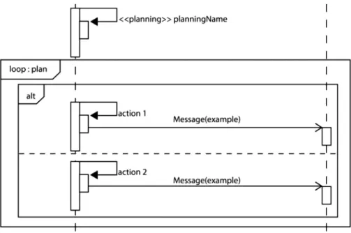
In MAS-ML 2.0 the agent actions are modelled by using the iter-ation element and combined fragment, which are already defined in UML. This representation allows the modelling of any combination of actions. An example is shown inFig. 21. Since the sequence of actions for the agents with planning is generated at runtime, the modelling of this sequence is not required.
The Goal-Based Agent with planning uses the representation pro-posed bySilva and Lucena (2004), as well as the plan defined during the design phase. In the case of Goal-Based Agent with planning, it
Fig. 21. Implementation of the actions of the agent with planning in the Sequence Diagram of MAS-ML 2.0.
Fig. 22. Simple Reflex Agent in Sequence Diagram.
initially runs perception, then next function, formulate-goal function and formulate-problem function. The planning function is executed and its output is a sequence of possible actions.
Finally, the Utility-Based Agent needs the perception, next func-tion, formulate-goal funcfunc-tion, formulate-problem funcfunc-tion, planning, utility function and results in actions that are performed in the predefined order.
5.3.2. Representation of Simple Reflex Agent in Sequence Diagram
The Simple Reflex Agent starts by executing its perception fol-lowed by the actions executed according to the condition-action rules.Fig. 22shows the Simple Reflex Agent in a Sequence Diagram. The agent perceives the environment and acts by executing an ac-tion that changes the environment or that sends a message to another agent.
5.3.3. Representation of Model-Based Reflex Agent in Sequence Diagram
The Model-Based Reflex Agent starts by executing its perception. Then, the next-function is executed followed by the actions executed according to the condition-action rules.Fig. 23shows the Model-Based Reflex Agent in a Sequence Diagram. The agent perceives the environment and acts by executing an action that changes the envi-ronment or that sends a message to another agent.
5.3.4. Representation of Goal-Based Agent in Sequence Diagram
The Goal-Based Agent starts its execution by perceiving the en-vironment. Then, the next-function is executed followed by the
Fig. 23. Model-Based Reflex Agent in Sequence Diagram.
formulate-goal function and the formulate-problem function. The actions are then executed according to the selected goal and plan. Fig. 24 shows the Goal-Based Agent in a Sequence Diagram. The agent perceives the environment and acts by executing an action that changes the environment or that sends a message to another agent.
5.3.5. Representation of Utility-Based Agent in Sequence Diagram
The Utility-Based Agent starts its execution by perceiving the environment, executing the next-function and performing the formulate-goal function and formulate-problem function. The ac-tions are executed according to the chosen plan that considers the related utility-function.Fig. 25shows the Utility-Based Agent in a Sequence Diagram. As in the previous agents, the agent perceives the environment and acts by changing the environment or sending a message.
5.4. Representation of AgentClass in Activity Diagram
The features proposed bySilva et al. (2005)and used in the Ac-tivity Diagrams were reused. Thus, each acAc-tivity is represented by a rounded rectangle. The agent beliefs are represented by a square with the identification of the agent used by the beliefs and goals in the upper-right corner through a textual description denoted by the
<<Goal>> stereotype.
5.4.1. Elements representation of reactive agents in Activity Diagram
The Activity Diagram of simple and Model-Based Reflex Agents represents the behaviour from perception to action. The behaviour of a Simple Reflex Agent is represented as follows: the initial activity is
Fig. 24. Goal-Based Agent in Sequence Diagram.
Fig. 25. Utility-Based Agent in Sequence Diagram.
Fig. 26. Simple Reflex Agent in Activity Diagram.
Fig. 27. Model-Based Reflex Agent in Activity Diagram.
the perception of the agent and, on the basis of the current percep-tion, the condition action rules are used to select one of the possible actions. Finally, the selected action is performed.Fig. 26shows the Simple Reflex Agent in Activity Diagram.
On the other hand, the behaviour of a Model-Based Reflex Agent is represented as follows: the initial activity is the perception of the agent that can be used by the next function to update its beliefs. After that, the condition-action rules are responsible for selecting one of the possible actions. Finally, the selected action is performed.Fig. 27 shows the Model-Based Reflex Agent in Activity Diagram.
5.4.2. Elements representation of proactive agents in Activity Diagram
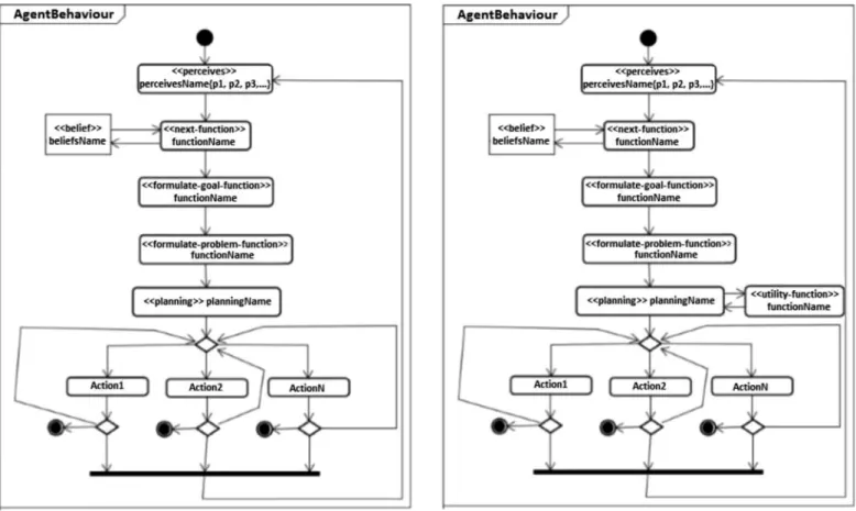
The Activity Diagram of the Goal-Based Agent with planning rep-resents the agent behaviour from perception to action. The behaviour of a Goal-Based Agent is represented on the Activity Diagram of MAS-ML 2.0 as follows: the initial activity is the perception of the agent and after that the next function updates the beliefs based on the current perception. The formulate goal and the formulate-problem functions are executed. The planning is performed to determine the action(s) that should be taken. Finally, the selected action(s) is performed. Fig. 28shows the Goal-Based Agent in Activity Diagram.
Fig. 28. Goal-Based Agent in Activity Diagram.
The behaviour of a Utility-Based Agent is represented on the Activ-ity Diagram as follows: the initial activActiv-ity is the perception, then the next function updates beliefs based on the current perception. The formulate-goal function and the formulate-problem function are exe-cuted. The planning is performed to determine what action(s) should be taken. The utility function helps in the choice of the action, and the selected actions are performed.Fig. 29shows the Utility-Based Agent in Activity Diagram.
6. MAS-ML tool
This section presents the functions, technologies, existent mod-elling tools for MAS and details related to the development of the MAS modelling environment called MAS-ML tool. Initially, the pro-cess of tool generation is described. This is followed by a description of the development of each diagram with the respective elements represented. Finally, an overview of MAS-ML tool is shown.
6.1. Background of MDA
MDD (model-driven development) is characterized by a focus on modelling and not on implementation (France and Rumpe, 2007). This approach provides automation through the implementation of changes that may involve model-to-model or model-to-text.
Based on the MDD, the OMG (object management group) defines an architecture called MDA (Model-Driven Architecture) that aims to standardize and facilitate the integration of resources used. This ar-chitecture is based on a set of standards, such as Unified Modelling Language (UML) with MOF (Meta Object Facility), XMI (XML Meta-data Interchange) and CWM (Common Warehouse Metamodel), that offers some core models or profiles for development (OMG, 2014a).
OMG also defines patterns for the code generation process, which utilizes a set of input instructions (these can be models) and gives
Fig. 29. Utility-Based Agent in Activity Diagram.
Fig. 30. MDA process. Available in http://research.petalslink.org/pages/viewpage. action?pageId=3639295.
as output the related source code. This standard establishes that the OMG concepts can be applied to different modelling languages, that is, they are not necessarily linked to a specific platform such as UML (OMG, 2014b).
The code generation process can be divided into stages. The con-cepts of each phase of code generation process are illustrated in Fig. 30and hereafter described:
• CIM (Computation Independent Model): Focuses on the under-standing of requirements to specify the application domain. • PIM (Platform Independent Model): Defines system entities and
their associated relationships.
• PSM (Platform Specific Model): The code generation will be held in a particular programming language and can use compo-nents, frameworks, middleware and libraries. Therefore, defini-tions need to be made in this regard.
• PDM (Platform Definition Model): Because the PSM is chosen, it is necessary to create relations between the elements present in the PIM and PSM.
6.2. Modelling tools for MAS
Based on the MDA approach, some modelling tools were proposed for modelling MAS. MAS-ML has a tool available; it was proposed by De Maria et al. (2005)for an MDA approach. However, this tool does not have available code; consequently, the application of extension proposed in this work and any changes cannot be applied in this tool. Cervenka (2012)describes profiles defined to IBM Rational Rose, En-terprise Architect and StarUML; all three tools provide the customiz-ing mechanisms for defincustomiz-ing and applycustomiz-ing UML profiles in the appli-cation models; therefore, implementation of UML profiles for AML is straightforward. AUML cites a set of tools that can support AUML; however, a profile definition is necessary to introduce the AUML syntax in UML tools.
Moreover, the modelling tools presented in this section do not present a description of internal architecture of agents, their inter-nal elements and the respective roles. MAS-ML tool can represent the internal architectures of Simple Reflex Agents, Model-Based Reflex Agents, Goal-Based Agents and utility agents.
6.3. Tool implementation
The MAS-ML tool is a modelling environment that supports the modelling of multi-agent systems based on the metamodel of MAS-ML. After defining the metamodel of the language, that is, the abstract syntax of the language, we felt the need for implementing a mod-elling tool to give support to the concrete syntax of the language. The tool was developed based on the model-driven approach proposed by the Graphical Modelling Framework (GMF, 2011). The development process proposed by the framework is divided into six steps (Domain Model, Graphical Definition Model, Tool Definition Model, Mapping Model and Domain Generation Model). These six steps were applied in the development of MAS-ML 2.0 tool, as follows:
Domain Model. First, the MAS-ML metamodel was specified
using EMOF (Essential Meta-Object Facility), a metamodel definition language. The predefined stereotypes were added to ActionClass by ActionSemantics resource, as follows: 0 – without stereotype, 1 – next-function, 2 – utility-function, 3 – formulate-problem-function and 4 – formulate-goal-function.
Graphical Definition Model. In this step the entities, its
prop-erties, and relationships were defined by following the metamodel.
Tool Definition Model. The elements used in each palette are
de-fined in this step. This step receives the domain model and definition model cited previously.
Mapping Model. In this step a mapping linking the domain
mod-els, graphical model and tool model is built. The generated mapping is used as input of the transformation process, which creates a specific modelling platform. The MAS-ML tool incor-porates a model-checking mechanism in order to validate the construction of the diagrams. A set of six validation rules de-fined by using OCL (Object Constraint Language) (OCL, 2011) is used to check if the model was correctly formed (Table 2). Class, Organization, Role, Sequence and Activity Diagrams use these rules.
Tool Generation. The next step follows the generative approach
proposed inCzarnecki and Eisenecker (2000)where the code is generated based on the model. Thus, GMF is used since it provides a generative component and a runtime infrastructure to develop graphical editors. The development process of each diagram is described below.
• Class Diagram. The Class Diagram of the MAS-ML tool was
devel-oped according to the steps listed inSection 6. Its Domain Model was created with the entities and relationships already defined in MAS-ML 2.0, and other steps were followed culminating in the tool generation. The Class Diagram contemplates the following el-ements: (i) Nodes: Class, AgentClass, OrganizationClass, Environ-mentClass, ActionClass, PlanClass, Property, Operation, Goal, Be-lief, Perception and Planning; (ii) Relationships: Association, In-habit, Dependency, Generalization, Aggregation and Composite; and (iii) Notes.
• Organization Diagram. The Domain Model generated when
creat-ing the Class Diagram was used to create the Organization Dia-gram that contemplates the following: (i) the relationships own-ership and play, (ii) agent role and object role, and (iii) agent, orga-nization and environment. These new elements are covered in the domain model and graphical model that were used in the Organi-zation Diagram. However, some adjustments in the domain model were required. The inhabit relationship has its semantics changed to allow agents and organization to inhabit the environment. The association, dependency, generalization, aggregation and compo-sition were removed because they are not part of Organization Diagram.
• Role Diagram. The same Domain Model was used to create the
Role Diagram. The elements that appear in both organization and Role Diagrams were preserved. The preserved entities are Agent Role and Object Role and the preserved relationships are Associ-ation, Control, Dependency, Generalization and Aggregation rela-tionships. The graphical representation of elements, relationships and diagrams of MAS-ML tool are presented through a case study in the next sections.
• Sequence Diagram. The creation of the Sequence Diagram was
started by mapping all the elements presented in the MAS-ML metamodel to Emfatic 2.0 language (Emfatic, 2014). In this process we associate the elements presented in the Sequence Diagram with their graphical representations. The elements presented in the diagram are as follows: Class, AgentClass, OrganizationClass, EnvironmentClass, ControlStructures, AgentRoleClass, PlanClass, ActionClass, Planning, and Perception. Graphical representations of Class, AgentClass, AgentRoleClass, OrganizationClass, and Envi-ronmentClass in the diagram are illustrated inFig. 31.
The relationships present in the Sequence Diagram are as follows: Action, AgentMessage (Activate, Cancel, Commitment, Create, Deacti-vate, Default, Destroy), Change (DeactivateReactiDeacti-vate, DeactivateCre-ate, DestroyCreDeactivateCre-ate, DestroyReactivate), For, If, Else, ObjectMessage, Perception, Plan, and Planning as depicted inFig. 32.
• Activity Diagram. The Activity Diagram was created according to
the same approach followed in the creation of the Sequence Di-agram. The metamodel of the MAS-ML 2.0 was transcribed to
Fig. 32. The representation of ML relationships in the Sequence Diagram of
MAS-ML tool.
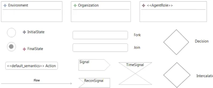
Emfatic language, the elements were identified and their repre-sentations were defined. The elements are Environment, Organi-zation, Role Agent, Initial State, Final State, Decision, Intercalation, Join, Fork, and Action. Environment, Organization, Role and Agent. Initial State and Final State mark the beginning and end of the ex-ecution of the activity respectively. Decision represents the con-ditional where the flow can follow a certain path depending on a predetermined value. Intercalation element determines the end of a decision, where paths that can be taken through a Decision converge. Fork represents the beginning of a run in parallel, and Join represents the point of synchronization between executions in parallel. The Action element represents the action performed by the agent, and the relationship Flow indicates the flow of actions that the agent performs. InFig. 33we show the main elements
presented in the Activity Diagram using the same representation of the tool itself.
6.4. Overview of the MAS-ML tool
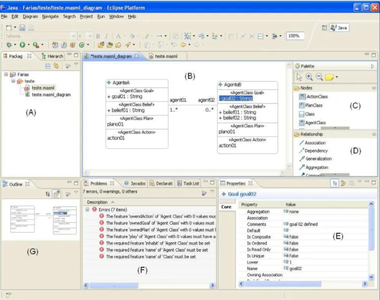
The deployed environment is a plug-in of Eclipse platform (Eclipse, 2013). Thus, the user can use the same environment to cre-ate models and code artefacts making use of the features offered by the platform. Given that many frameworks, including JADE, Jadex (Braubach et al., 2004), and Jason (Bordini et al., 2007), are based on the Java platform, the integration of frameworks from differ-ent sources and purposes helps developers to implemdiffer-ent MAS and favours the code generation within the same development environ-ment.Fig. 34shows a Class Diagram view from the MAS-ML tool. The main components in the interface are highlighted by letters. Each component has a specific function in the tool, according to the following:
Package Explorer (A). For each new modelling project, the files that are used during the modelling process are created and im-ported, for example, libraries, text documents, and images. The package explorer embodies the core functionalities allowed in a tree structure of files in order to improve their management and manipulation.
Modelling View (B). The models that are created must necessar-ily be viewed in order to meet two basic requirements: un-derstanding and communication. In this sense, the modelling view allows developers to view and edit the templates interac-tively.
Palette Nodes (C). The builders that are part of the diagrams pro-posed by MAS-ML are the nodes and relationships palette. Thus, developers can create instances of these constructors that are displayed in the modelling view. It is possible to iden-tify inFig. 34some of these elements such as ActionClass and AgentClass, for example.
Relationship Palette (D). The relationships that can be established between manufacturers present in nodes are available in the palette relationship. InFig. 34it is possible to identify some of these relationships, for example, the association established between these two agents (i.e. AgentA and AgentB) shown in modelling view.
Properties View (E). Ever-present concerns during the develop-ment of the MAS-ML metamodel are (i) the identification and representation of the characteristics of the properties of the MAS-ML metaclasses; and (ii) the organization and manage-ment of the properties that are inherited from metaclasses
Fig. 34. An MAS-ML tool overview. are extended from the UML to avoid creating conflicts or
in-consistencies. These properties define exactly the models and are used, for example, to distinguish the models presented in the diagrams. Looking atFig. 34, the difference between the two agents presented in the modelling view is the difference between the Strings “AgentA” and “AgentB” attributed to its name property. Thus, the importance of properties view is ev-ident because it allows the manipulation of the model proper-ties. This view displays the properties defined in the MAS-ML metamodel when the model is displayed and selected in the modelling view. InFig. 34the properties of AgenteB.goal02 can be seen.
Problems View (F). Given the need for validating the created models, the tool provides developers with a functionality of model validation. That is, the tool allows developers to check if the created model has (or not) inconsistencies considering the MAS-ML metamodel. If any inconsistency is detected, then they will be reported in the problem view.Fig. 26shows some problems captured. In this case, the following well-formed rules are not respected: (i) every agent must have an action, (ii) every agent should have a goal, (iii) every agent must have a plan, and so on. These inconsistencies are compared with the model presented in (B). This feature is particularly impor-tant to enable the use of modelling MASs within the context of
model-driven development, in which models are seen as first-order artefacts. Inconsistent models impair the transformation of models in model-centric software development.
Outline View (G). An overview of the distribution of the model elements can be seen in the outline view.
The MAS-ML tool code and generated plug-ins are available in https://sites.google.com/site/uecegessi/masmltool.
7. Case study
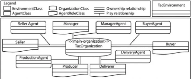
TAC-SCM application is used to illustrate the benefits of TAO and MAS-ML 2.0 where agents with different architectures are elicited to model different strategies to the problem solution.Section 7.1 de-scribes the TAC-SCM environment,Section 7.2shows the agents and agent roles by using the TAO templates (TAO templates were pre-sented inSection 4) andSection 7.3shows the MAS models done in the MAS-ML modelling tool that follows the specification of MAS-ML 2.0.
7.1. TAC-SCM
TAC (Trading Agent Competition) (Wellman et al., 2002) is an en-vironment that enables the achievement of simultaneous auctions,