UNIVERSIDADE DA BEIRA INTERIOR
Engenharia
Single droplet ignition and combustion of jet-A1,
hydroprocessed vegetable oil and their blends in
a drop tube furnace
(Versão final após defesa)
Gonçalo de Sousa Pina Pernicha Pacheco
Dissertação para obtenção do Grau de Mestre em
Engenharia Aeronáutica
(ciclo de estudos integrado)
Orientador: Prof. Doutor André Resende Rodrigues da Silva
Co-orientador: Prof. Doutor Mário Manuel Gonçalves da Costa
Este trabalho foi realizado no âmbito da obtenção do grau de mestre de Gonçalo
de Sousa Pina Pernicha Pacheco. Foi desenvolvido numa parceria entre a
Universidade da Beira Interior e o Instituto Superior Técnico. O grau de mestre
foi concedido pela Universidade da Beira Interior e o trabalho experimental
decorreu no Instituto Superior Técnico.
Dedicatória
Em memória dos meus bisavós Manuel de Sousa e Ana de Sousa, que me ensinaram o que é o espírito de luta e perseverança. Obrigado por terem iniciado comigo este caminho e é com muita saudade que não têm a possibilidade de o verem terminado.
Acknowledgments
Firstly, I would like to express my sincere gratitude to my supervisors, Professor André Silva and especially Professor Mário Costa for providing me this opportunity and for all the support, knowledge and guidance. It was a challenge that helped me grow as an engineer and as a person.
I also sincerely thank Manuel Pratas for his technical support during the design of the experimental setup and for bringing always good mood to the laboratory. I would like to thank Pedro Rijo for his support during experimental tests and for the good debates about the experimental results, his help was indispensable during this work.
To my colleagues who I consider my friends, I want to thank them for their friendship, support and unique moments.
I would like to thank especially to Inês Ferrão who gave me all the love and suppord, and stayed by my side in every difficult time.
Lastly, I would like to express my gratitude to my family who always believed in me. Particularly to my parents and grandparents, for their unconditional support especially in the last difficult years. Without them, this journey would not be possible.
Resumo
O impacto ambiental e a dependência de combustíveis fósseis no setor aeronáutico promoveram a procura por combustíveis alternativos e ecológicos. Este é um dos principais desafios para este setor no futuro. Uma possível solução num futuro próximo pode ser a mistura de biocombustíveis com combustível de aviação, o que permitiria o uso de combustível mais ecológico e a redução de gases de efeito estufa e emissões sem alterações significativas nas frotas existentes das empresas, isto é, o desenvolvimento de um combustível “drop-in”. Neste contexto, este trabalho examina as características de ignição e combustão de gotas isoladas de jet-A1 (JF), óleo vegetal hidroprocessado (NExBTL) e suas misturas num forno de queda livre (DTF). O objetivo deste trabalho é avaliar a influência da composição da mistura nas características do combustível. Gotas com diâmetros de 155 ± 5 μm, produzidas por um gerador comercial de gotas, foram injetadas no DTF, cuja temperatura da parede e concentração de oxigênio eram controladas. Os testes foram conduzidos para três temperaturas (900, 1000 e 1100 ºC). A ignição e a combustão das gotículas foram avaliadas através das imagens obtidas com uma câmara de alta velocidade acoplada a uma lente de alta ampliação e um algoritmo de deteção de limites. As imagens permitiram a observação dos fenómenos de queima e avaliar a evolução temporal do tamanho das gotas e das taxas de queima. Os resultados revelaram que as misturas de combustível seguem a lei D2, exceto a mistura com 75% de JF para uma
temperatura de 1100 ºC na parede do DTF. Isso ocorreu devido à ocorrência de puffing e micro-explosões, o que aumentou as taxas de queima. Observou-se ainda que as misturas com maior teor de JF apresentam chamas com maior intensidade luminosa e maiores taxas de queima.
Palavras-chave
Abstract
The environmental impact and the dependence of fossil fuels in the aeronautical sector have promoted the demand for alternative and greener fuels. This is one of the main challenges for this sector in the near future. A possible solution in the near future might be the blending of biofuels with jet fuel, which would allow the use of greener fuels, and a reduction in the greenhouse gases and emissions without significant changes in the existing fleets of the companies, which means the development of a “drop in” fuel. In this context, this work examines the ignition and the combustion characteristics of single droplets of jet-A1 (JF), hydroprocessed vegetable oil (NExBTL) and their mixtures in a drop tube furnace (DTF). The objective of this work is to evaluate the influence of the fuel mixture composition on the fuel characteristics. Droplets with diameters of 155 ± 5 μm, produced by a commercial droplet generator, were injected into the DTF, whose wall temperature and oxygen concentration were controlled. Experiments were conducted for three temperatures (900, 1000 and 1100 ºC). The ignition and combustion of the droplets were evaluated through the images obtained with a high-speed camera coupled with a high magnification lens, and an edge detection algorithm. The images allowed for the observation of the burning phenomena, and data are reported for temporal evolution of droplet sizes and burning rates. The results revealed that the fuel mixtures followed the 𝐷2 law, except the mixture with 75% JF for a DTF wall temperature of
1100 ºC. This was due to the occurrence of puffing and micro explosions, which enhanced the burning rates. In addition, it was observed that the mixtures with a higher content of JF present brighter flames, and higher burning rates.
Keywords
Single droplet, jet fuel, hydroprocessed vegetable oil, mixtures, ignition, combustion, micro explosion, puffing
Index
Dedicatória ... v Acknowledgments ... vii Resumo ... ix Palavras-chave ... ix Abstract ... xi Keywords ... xi Index ... xiiiList of figures ... xvii
List of tables ... xxi
Nomenclature ... xxiii
List of acronyms ... xxv
1. Introduction ... 1
1.1. Motivation ... 1
1.2. State of the art ... 3
1.2.1. Engine emissions and environmental impact ... 3
1.2.2. Fundaments of single droplet combustion ... 6
1.2.2.1. Droplet evaporation ... 6
1.2.2.2. Basic evaporation/combustion model ... 7
1.2.2.3. Effects of ambient temperature ... 8
1.2.2.4. Effects of forced convective flow ... 9
xiv
1.2.2.6. Multi-component fuel droplets ... 11
1.2.2.7. Influence of inter-droplet spacing ... 11
1.2.2.8. Physics of puffing and micro explosions ... 12
1.3. Alternative jet fuels ... 13
1.4. Jet fuel ... 17
1.5. Overview ... 18
1.6. Objectives of this work ... 18
2. Materials and methods ... 21
2.1. Experimental setup ... 21
2.1.1. Experimental facility ... 21
2.1.2. Drop tube furnace ... 26
2.1.3. Droplet generator system ... 28
2.2. Droplet imaging technique and acquisition system ... 31
2.2.1. Edge detection algorithm ... 33
2.2.2. Ignition criteria ... 34
2.3. Fuel characterization ... 352.3.1. Density ... 36
2.3.2. Viscosity ... 36
2.3.3. Surface tension ... 36
2.3.4. Cetane number ... 36
2.3.5. Sulfur content ... 37
2.3.6. Flash point ... 37
2.3.7. Jet-A1 ... 37
2.3.8. NExBTL ... 37
3. Results and discussion ... 39
3.1. Droplet characterization ... 39
3.2. Visualization of the single droplet combustion ... 42
3.3. Occurrence of micro explosions ... 43
3.4. Droplet size evolution and burning rate ... 44
4. Closure... 51 4.1. Conclusions ... 51 4.2. Future work ... 51 5. References ... 53 Annex ... 57 Annex 1 ... 58
List of figures
Figure 1.1: Expected growth for aircraft global fleet . ... 1
Figure 1.2: Schematic showing the ideal and real combustion processes for aero-engines . .... 4
Figure 1.3: RF components associated with aviation. Bars show the best estimate available and include an estimate as to the confidence level in the data . ... 5
Figure 1.4: Schematic of a single droplet burning. ... 7
Figure 1.5: Measured ignition delay time versus droplet diameter for n-heptane droplets for different ambient gas temperatures . ... 9
Figure 1.6: Schematic of Inter droplet interaction . ... 10
Figure 1.7: The influence of droplet spacing in the Ignition delay time. ... 12
Figure 1.8: Sequence regarding nucleation, bubble growth, and the breakup of parent droplet: (a) Schematic of puffing; (b) Micro explosions. ... 13
Figure 1.9: Lower calorific value as a function of density for a range of liquid fuels. ... 15
Figure 1.10: Transesterification process. ... 16
Figure 1.11: FT production process. ... 16
Figure 1.12: Hydroprocessing of vegetable oil. ... 17
Figure 2.1: Schematic of the experimental setup. ... 21
Figure 2.2: Technical draw of the injector part 1 (units are displayed in mm). ... 23
Figure 2.3: Technical draw of the injector part 2 (units are displayed in mm). ... 24
Figure 2.4: Technical draw of the injector part 3 (units are displayed in mm). ... 24
Figure 2.5: Fully assembled injector. ... 25
Figure 2.6: Exploded view of the assembled injector. ... 25
Figure 2.7: Ambient temperature as a function of the vertical distance from the injector tip at 900 ºC. ... 26
xviii
Figure 2.8: Ambient temperature as a function of the vertical distance from the injector tip at
1000 ºC. ... 27
Figure 2.9: Ambient temperature as a function of the vertical distance from the injector tip at 1100 ºC. ... 27
Figure 2.10: Schematic of the droplet generating system . ... 28
Figure 2.11: Schematic for the method for producing a monosize stream of droplets . ... 29
Figure 2.12: Representation of a) Syringe pump; b) Signal generator. ... 29
Figure 2.13: Representation of a) Droplet generator b) Rotating disk. ... 31
Figure 2.14: Schematic of backlighting image setup. ... 32
Figure 2.15: Image acquisition system. ... 33
Figure 2.16: 100% JF droplet burning at 1100ºC... 33
Figure 2.17: Edge detection example. ... 34
Figure 3.1: Droplet velocity as a function of the normalized diameter. ... 41
Figure 3.2: Droplet Reynolds number as a function of the normalized diameter. ... 41
Figure 3.3: Sequences of instantaneous images of burning droplets at different temperatures: a) 1100 ºC; b) 1000 ºC; c) 900 ºC. ... 43
Figure 3.4: Characterization of the micro-explosions for the fuel mixture with 75% of jet-A1 at 1100 ºC: a) Frequency of micro-explosions; b) droplet diameter at the micro-explosion instant. ... 44
Figure 3.5: Normalized 100% JF droplet diameter as a function of the normalized time at different temperatures. ... 45
Figure 3.6: Normalized droplet diameter as a function of the normalized time at 1100 ºC. .. 46
Figure 3.7: Normalized droplet diameter as a function of the normalized time at 1000 ºC. .. 46
Figure 3.8: Normalized droplet diameter as a function of the normalized time at 900 ºC. .... 47
Figure 3.10: Droplet burning rate as a function of the normalized time at 1000 ºC. ... 48 Figure 3.11: Droplet burning rate as a function of the normalized time at 900 ºC. ... 49 Figure 3.12: Global burning rates as a function of the temperature. ... 50
List of tables
Table 2.1: Fuel properties. ... 35
Table 3.1: Air density for each operating condition. ... 40
Table 3.2: Flow properties for each condition. ... 40
Nomenclature
Symbol Designation
Units
CN Cetane number —
𝑐𝑝,𝑔 Specific heat at constant pressure [𝑘𝐽/(𝑘𝑔. 𝐾)]
D Droplet diameter [𝑚𝑚]
𝐷0 Initial droplet diameter [µ𝑚]
f Excitation frequency [𝑘𝐻𝑧]
FP Flash point [º𝐶]
FT Fischer–Tropsch —
G Combustion group number —
HHV High heating value [𝑀𝐽/𝐾𝑔]
Iw Wobbe index —
K Burning rate [𝑚𝑚2/𝑠]
LCV/LHV Lower calorific value [𝑀𝐽/𝐾𝑔]
M-E Micro explosion —
𝑝 Pressure [𝑃𝑎]
Q Volumetric flow rate [𝑚𝑙/𝑚𝑖𝑛]
𝑅𝑑 Gas constant [𝑘𝐽/(𝑘𝑔. 𝐾)]
RF Radiative forcing [𝑊/𝑚2]
ReD Droplet Reynolds number —
Re Reynolds number —
𝑆
Sutherland temperature [º𝐾] 𝑆𝑐 Schmidt number —𝑆𝐺
Specific Gravity — t Time [𝑠] 𝑇 Temperature [º𝐶]Greek symbols
µ
Dynamic viscosity [𝑃𝑎. 𝑠]𝜌
Density [𝑘𝑔/𝑚3]xxiv
Subscripts
0 Initial𝑎𝑚𝑏
Ambientliq
Liquidd
Droplet lifetimeg
GasList of acronyms
AJF Alternative jet fuel BtL Biomass to liquid
DGS Droplet generator system DTF Drop tube furnace FAE Fatty acid ester FAEE Fatty acid ethyl ester FAME Fatty acid methyl ester Fps Frames per second FT Fischer–Tropsch GHG Greenhouse gases GTL Gas to liquid
HEFA Hydroprocessed esters and fatty acids HVO Hydroprocessed vegetable oil
HC Hydrocarbons
HRJ Hydroprocessed renewable jet fuel IAS Image acquisition system
ISA International standard atmosphere ICAO International civil aviation organization ROI Region of interest
Chapter 1
1. Introduction
In this chapter, the motivation of this study is presented in order to explain the importance of it. Thereafter, a literature review was elaborated to provide support, which includes the relevant studies for the present work.
1.1. Motivation
In just over 100 years, the aeronautical sector has had a notorious impact on the emergence of new markets. Consequently, new goods and services became essential in modern-day life. Commercial aviation has become a global business of around 22680 aircraft currently operating on a single fossil fuel. The sector is responsible for 2-3% of global carbon emission and it is expanding relatively fast with a predicted growth of 4.7% per year. This means that today’s fleet will grow to almost 47680 aircraft by 2038 [1,2].
2
This rapid growth, coupled with the continuous increase in fuel prices and carbon emissions, which are expected to be up to 80% [4], have inspired research for a new alternative fuel that could supply the sector and reduce the environmental impact. Biofuels are attractive candidates due to its low greenhouse gases emission (GHG) and the decrease of the dependence on fossil fuel sources [5]. The use of biofuels can be a path to GHG reduction since most of the CO2 released in burning the fuel would have been removed from the atmosphere while the plant
was growing. Nevertheless, the environmental impact of the aeronautical sector exceeds the problem of the CO2 emission because several pollutant agents are also produced during the
fuel-burning process. These include soot, NOx, unburned hydrocarbons and sulfur oxides, which
have a negative impact on the air quality in areas near airports.
In the last 40 years, the fuel efficiency of jet aircraft has been estimated to be improved by more than 60% in terms of emissions of CO2/passenger/km. Several improvements have come
from step changes in technology, such as enhanced engine efficiency, airframe aerodynamics, and lighter materials, However the achievement of these ambitious goals remains challenging with current levels of Government and industrial investment in the relevant research and demonstration activities. As one approaches the theoretical limits, efficiency gains are much harder to achieve. This is the case with turbofan engines that can only be improved by up to 30% before theoretical limits are reached [4]. Other possible solutions may come from alternative fuels, that offer some advantages in the long term. The development of alternative fuels allows a faster benefit, as it is not constrained to the industrial assets of the aeronautical sector, in which the high investment costs slow the renovation of the production [4]. Moreover, the use of alternative fuels presents further advantages over the use of conventional jet fuel, as a reduced cost fluctuation, a worldwide homogeneous distribution of the feedstock depending on the alternative fuel production [5]. For these reasons, the contribution of alternative jet fuel is expected to grow by up to 30% by 2030 [1]. This poses a challenge because the aeronautical sector requires fuels with high energy density and with well-specified properties in order to comply with the current legislation. Any product proposed must be fully interchangeable with the existing jet fuel product to avoid the logistic problems of airports handling multiple fuels with varying qualities and the commercial limitations these would impose. For these reasons, the main research drive has been around the development of “drop-in” fuels, which can be used in the existing fleet, because the industry keeps its assets in use for around 40 years [1], due to the high investment costs.
One of the most promising candidates is a hydroprocessed vegetable oil (HVO) called NExBTL, which is a biofuel. This is a very promising fuel since it is already approved for blending ratios of 50/50 with conventional jet fuel and promotes less pollutant formation. Generally, running on a neat synthetic jet from hydrogenated processes reduces the emitted NOx by up to 12% [6]. This reduction in emissions while running on alternative fuels has been shown in engine demonstration flights. An excellent example was given by the Japan airlines that demonstrated
the feed-stock independence of hydroprocessed jet fuel through incident free operating of one of its Boeing 747-300. The roundtrip test flight operated one of four engines on a 50%/50% blend of conventional jet fuel and hydroprocessed biomass feedstock. The success of recent test campaigns has not only highlighted biomass product compatibility for gas turbines but also demonstrated the technological readiness and feedstock independence of the hydrotreatment process [7].
One of the biggest concerns with the use of alternative fuels has come from their low aromatic content. Seals in the aircraft and engine would leak if the aromatic content is lower than the specified values − the seals would shrink. For this reason, the aromatic content of synthetic fuel blends is currently fixed at a minimum of 8%. The performance of alternative fuels concerning particulate emissions has received considerable attention. Most works that evaluated biomass to liquid (BtL) or hydroprocessed renewable jet fuel (HRJ) has indicated a reduction in particle matter emissions. This is primarily due to the decrease in the aromatic content of the fuel. The main goal of this work is to study the burning characteristics of the different fuel mixtures, particularly to evaluate the effect of blending different amounts of HVO and JF in the burning behaviour of droplets to increase the knowledge on multicomponent fuels. Even though engine studies provide very useful information regarding fuel performance under realistic conditions, results can be dependent on several noncontrollable variables. On the contrary, in single droplet studies most parameters affecting the results are well known and controllable, and therefore the combustion characteristics observed are intrinsically attributable to the fuel.
1.2. State of the art
1.2.1. Engine emissions and environmental impact
In real combustion processes, air and fuel are mixed, ignited, and burnt to release heat. In ideal combustion, this process generates CO2, water (H2O) and sulfur dioxide (SO2) depending
on the fuel composition. However, real combustion is a multi-step process involving hundreds of intermediate reactions that affect the process and produce additional emissions. These additional emissions are usually considered pollutants, and include oxides of nitrogen (NO and NO2) referred to as NOx, unburnt hydrocarbons (UHCs), carbon monoxide (CO), soot and sulfur
oxides (SO2, SO3, and H2SO4) referred to as SOx. Figure 1.2 shows a schematic of the emissions
from an aero engine. The amount of additional pollutants depends on the conditions in the combustion chamber (temperature, pressure, air-fuel ratios, and geometry of the combustor chamber) [4]. The international civil aviation organization (ICAO) regulates emissions with local air quality impacts (being the main ones NOx, UHC, CO, smoke, and SOx). CO2 emissions are
4
the industry and can outpace legislation, even though this reduction isn´t enough to achieve carbon neutral growth.
Figure 1.2: Schematic showing the ideal and real combustion processes for aero-engines [3]. NOx is formed from the oxygen and nitrogen in the air reacting at high temperatures in the combustor. The net effect of NOx on global warming is debated. Trough photochemical reaction in the troposphere it increases the tropospheric ozone [8] concentration and through liberating OH radicals it reduces the lifetimes of other GHGs such as methane (CH4) [9]. The net result is
thought to be a slight warming effect. The major impact and reason for legislation for emissions of NOx are due to its effects on local air quality near the airports.
SOx is a pollutant that contributes to the acidity of rainwater and generates health risks, but it is not considered a GHG. The source of SOx is the sulfur content in fuels. Aviation kerosene has sulfur contents much lower than coal and fuel oil because sulfur contents have a negative impact on the turbine lifetime. The reason for do not remove sulfur from JF is because it would require a more energy-intensive and expensive refining process and the addition of a substitute lubricant for the fuel system.
UHCs and CO are pollutants that contribute to the petrochemical smog and ozone creation at tropospheric levels. They are both products of incomplete combustion. Modern aero-engines have very low UHC and CO emissions, although work is ongoing to reduce them during starting and low-power idling.
Aviation’s contribution to the tropospheric water vapor is very small compared to the natural hydrological cycle [10], but a aviation-induced warming effect is attributed to the fraction of H2O transmitted into the much dryer stratosphere, where it is a powerful warming agent.
Probably, more importantly, contrails can form from the engine exhaust at high altitudes, when the water crystallizes at very cold and wet ambient atmospheric conditions. Contrails can also
develop into cirrus clouds. These clouds trap outgoing longwave earth radiations at night, but in the daytime, they reflect sunlight. Their net effect may be a warming one, although difficult to quantify, this whole area remains one of great uncertainty and debate with the need for further quantitative research [4].
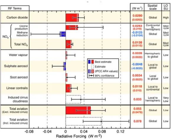
Figure 1.3 shows the radiative forcing (RF) components associated with aviation and a column that estimates the level of scientific understanding (LOSU). Over the years, several other studies have reported and updated the original estimates of the effects. RF is a measure of the change of energy balance of the earth’s atmosphere system in watts per square meter. Positive values quantify the net warming effect, while negative values show a cooling effect. The net numbers from aviation still remain low when compared to the incident radiation from the sun of 342 W/m2 [7].
Figure 1.3: RF components associated with aviation. Bars show the best estimate available and include an estimate as to the confidence level in the data [7].
6
1.2.2. Fundaments of single droplet combustion 1.2.2.1. Droplet evaporation
Droplet evaporation involving heat and mass transfer processes in a turbulent environment has great importance for engineering applications, such as the atomization, and gas turbine engines evaporation and combustion of liquid fuels in internal combustion engines. In such applications, the liquid undergoes several processes before it becomes vapor, which then mixes with the oxidant and burns to release energy [11]. To achieve a better performance of these systems and reduce the emission of pollutants, the first step might be the fundamental study of the previous processes in order to develop models/methods that are able to predict accurately evaporation rates and burning rates. A spray may be considered as a cloud of droplets, which are produced through the disintegration of a liquid jet issuing from a simple cylindrical nozzle or more complex injectors. It was shown that in the near fields of the injector tip, a dense region of ligaments and droplets having various sizes might occur, while on the far field, a dilute region of more uniform droplets. Interactions between droplets prevail in the dense region, while the aerodynamic transport of droplets is dominant in the dilute dispersed spray region. In spray combustion, the droplet vaporization rate is the dominant controlling factor of combustion. This conversion (liquid to vapor) can be referred to as boiling or as evaporation. Boiling occurs when the submerged surface needs to be heated to an above boiling temperature of the liquid. Evaporation occurs when the liquid is above boiling temperature or in the presence of a mix between incondensable gas and vapor.
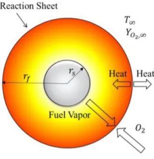
Figure 1.4 shows a schematic of a single droplet burning. In this process, mass and heat are transferred between the droplet and surrounding gas. Heat is transferred to the droplet surface by conduction and convection through the hot gas surrounding the droplet. Heat and mass transfer is affected by the droplet Reynolds number. Vaporization rates are affected by several factors such as temperature, pressure, fluid properties, surrounding gas properties, droplet diameter and droplet velocity relative to the gas. Depending on the locations in the spray, neighboring droplets might affect the vaporization rate in the spray. However, in spray evaporation and combustion computations, it is generally assumed that the overall spray behavior can be obtained by the summing behavior of individual isolated droplets surrounded by a gas phase that itself has varying properties. Even when the assumption that droplets behave as if they were isolated from each other is not satisfactory, the behavior of a single isolated droplet in an oxidizing environment will provide fundamental input to the overall spray analysis. From a practical point of view, the vaporization and combustion of single droplets are very important in understanding spray flows. The reason for its intensive investigations is that these relatively simple phenomena may be used to advance the knowledge of the complex mechanism of two-phase spray combustion encountered in liquid-fueled combustion systems.
Figure 1.4: Schematic of a single droplet burning.
1.2.2.2. Basic evaporation/combustion model
The basic droplet vaporization/combustion theory for an isolated single-component droplet in a stagnant environment was proposed by G. Godsave [12] and Spalding [13]. In this model, it is assumed that the droplet is spherical, the boiling point of pure fuel is well known, and radiation heat transfer is negligible − these assumptions are valid except for conditions of very low pressure or highly luminous flames.
After an initial transient period, steady-state evaporation is established from an analytical solution referred to as the “D2 law” [12]. In this solution, the droplet squared diameter
diminishes linearly with time according to:
𝑑
02− 𝑑(𝑡)
2= 𝐾𝑡
(1.1)This analytical solution is sometimes simply called the “D2 law” of droplet evaporation, K is
known as the evaporation constant given by:
𝐾 = 8𝜆𝑔 𝜌𝑙𝑖𝑞𝑐𝑝,𝑔
ln(𝐵𝑞+1) (1.2)
where 𝑐𝑝,𝑔 represents the specific heat at constant pressure and 𝜆𝑔 represents the thermal
conductivity. Experiments shows that “
𝐷
2 law” is valid after an initial transient period associated with droplet heating until a value near the boiling point.8
Once the initial diameter of the droplet is known and the evaporation constant (𝐾), the “
𝐷
2 law” is able to predict the droplet evaporation time, also known as the droplet lifetime (𝑡𝑑),asfollows:
𝐷
2(𝑡
𝑑
) = 0: 𝑡
𝑑=
𝐷02𝐾 (1.3)
Note that to use the previous equations it is required to know the mean values for the properties 𝑐𝑝,𝑔 and 𝜆𝑔, which are present in the evaporation constant 𝐾 [14].
Three parameters are generally evaluated: the mass burning rate (evaporation), the flame position above the fuel surface, and the flame temperature. The most important parameter is the mass burning rate that permits the evaluation of the so-called evaporation coefficient, which is most readily measured experimentally where 𝐷0 is the original drop diameter and 𝐷
the drop diameter after time 𝑡,
𝐷
2(𝑡) = 𝐷
02
− 𝐾𝑡
(1.4)1.2.2.3. Effects of ambient temperature
The ambient temperature is a significant factor because it affects evaporation rates, ignition and heating time. The significance of this parameter is addressed in this work.
Figure 1.5 shows the effect of ambient temperature in the ignition delay of a n-heptane droplet. High ambient temperature promotes droplet evaporation by providing enhanced heat transfer to the droplet surface, while allowing faster evaporation of the fuel components. This effect was observed in [15]. Authors made several numerical studies for n-heptane and concluded that the evaporation rate and burning rate showed a strong dependence on the ambient temperature, increasing monotonically with the ambient temperature. This phenomenon was also observed by [16]. Another very important factor affected by the ambient temperature is the ignition delay time. Several authors stated that the increase in ambient temperature leads to a decrease in ignition delay time [17].
Figure 1.5: Measured ignition delay time versus droplet diameter for n-heptane droplets for different ambient gas temperatures [17].
From the previously works from other authors, it was observed that the kerosene droplets followed the “
𝐷
2 law” after a heating period and that the ambient temperature was a very important parameter, which greatly affected ignition and combustion phenomena.1.2.2.4. Effects of forced convective flow
This section refers to the effects of forced convection on ignition delay and evaporation rate. In contrast with studies under stagnant conditions, there has been limited research on droplet ignition under convective conditions. Whang et al. [18] conducted an experimental study of the ignition of a suspended droplet in the convective post-flame environment of a flat-flame burner. The ignition delay and location were measured for n-heptane and n-hexadecane droplets for a range of ambient temperatures, droplet diameters, and droplet Reynolds number (ReD). Their results indicated that the minimum ambient temperature for ignition increases
significantly due to forced convection. Despite the different results in the literature, it can be concluded that the ignition location and flame development are strongly influenced by ReD. As
ReD increases, the ignition location moves from the front to the wake of the droplet, and
correspondingly an envelope flame changes to a wake flame. Further increase in ReD leads to
either no ignition or flame extinction [18]. Forced convection was found to impede droplet ignition in that the minimum ignitable gas temperatures were higher compared with natural convection [18]. Sangiovanni [19] states that for droplet spacings in excess of twenty droplet diameters convection reduces the ignition delay times [12].
10
1.2.2.5. Burning clouds
Each droplet in a cloud has a gas film surrounding it. The local ambient conditions are defined as the gas properties at the edge of the gas film but within the volume of the cloud. This definition becomes imprecise when the gas films of neighboring droplets overlap. In such case, the local ambient conditions would be replaced with some average over the gas in the droplet neighborhood [13,19]. Despite numerous analytical and experimental studies on burning droplet arrays, the current understanding on burning of clouds and sprays is still limited. Figure 1.6 shows a schematic of the different regimes of droplet interactions, and how they are affected by the group combustion number, G. The primary consideration in most studies has been the effect of droplet separation on the overall burning rate. An interesting approach to the spray problem has been suggested by Chiu and Liu [20] that consider a quasi-steady vaporization and diffusion process with infinite reaction kinetics. They show the importance of G, which was derived from extensive mathematical analyses as:
𝐺 = 3 (1 + 0.276𝑅𝑒
𝐷 1 2𝑆𝑐
1 2𝐿𝑒𝑁
2 3)
𝑅
𝑆
(1.5)Figure 1.6: Schematic of Inter droplet interaction [19].
where Re, Sc, and Le are the droplet Reynolds number, the Schmidt number, and the Lewis number, which are presented in annex 1. In Eq. (1.5), N is the total number of droplets in the cloud, R the instantaneous average radius, and S the average spacing between droplets. The value of G was shown to have a profound effect on the flame location and distribution of temperature, fuel vapor, and oxygen. Four types of behaviors were found for large G numbers. External sheath combustion occurs for the largest value. As G decreases, there is successively external group combustion, internal group combustion, and isolated droplet combustion. Isolated droplet combustion obviously is the condition for a separate flame envelope for each droplet. Typically, a group number less than 10−2 is required. Internal group combustion
flame [21] − this happens for G values above 10−2 and somewhere below 1. As G increases, the
size of the core increases. When a single flame envelops all droplets, external group combustion exists. This phenomenon begins with G values close to unity (many industrial burners and most gas turbine combustors work in this range). With external group combustion, the vaporization of individual droplets increases with distance from the center of the core. At very high G values (above 102), only droplets in a thin layer at the edge of the cloud vaporize. This regime is called
the external sheath condition [21].
1.2.2.6. Multi-component fuel droplets
There are various complications that occur when a multicomponent liquid is considered since different components vaporize at different rates, creating concentration gradients in the liquid phase and causing liquid-phase mass diffusion [13]. Due to this, the more volatile substances tend to vaporize faster at first until their surface’s concentration values diminished and further vaporization of those quantities becomes liquid-phase mass diffusion controlled. Mass diffusion in the liquid phase is of primary importance in the vaporization process for a multi-component fuel. At first, early in the droplet lifetime, the more volatile substances in the fuel at the droplet surface will vaporize leaving only the less volatile material that evaporates more slowly. More volatile material still exists in the droplet interior and will tend to diffuse toward the surface because of concentration gradients created by prior vaporization. This diffusion is balanced by the counter diffusion of the less volatile fuel components toward the droplet interior [16]. Classical droplet vaporization theory treats spherically symmetric, quasi-steady, single-component, isolated droplets. It is on the relaxations of these features where modern developments are concentrating. In real combustors, the local field around a droplet is not spherically symmetric but multi-dimensional; also, transient effects are significant. Real fuels are multi-compositional with varying volatilities of the components [16].
1.2.2.7. Influence of inter-droplet spacing
The inter-droplet spacing has great importance on the burning rates, ignition delay time, and flame position. Figure 1.7 shows the influence of droplet spacing in the ignition delay times. As the distance between droplets becomes larger, the influence of neighboring droplets becomes smaller − the transport and aerodynamic characteristics tend to the values of isolated droplets. On the contrary, if the space between droplets decreases, they cannot be treated as isolated droplets; the neighboring droplets are within the gas film or wake of the droplet. In a convective situation, a droplet can influence a second droplet at a distance of many tens of droplet radii if the latter is in its wake [13]. Sangiovanni discusses the various effects of the inter-droplet spacing in its experimental work [19]: the fuel droplet ignition delay times for small droplet spacings can be substantially greater than the delay times for isolated droplets; for small droplet spacings, the role of forced convection in heating and vaporizing droplets as a result of droplet/gas relative velocity becomes insignificant since each droplet travels in the wake of a
12
preceding droplet; and the effect of droplet interaction on the ignition process becomes more important for small droplets, low gas-phase temperatures, and fuels with low volatility.
Figure 1.7: The influence of droplet spacing in the Ignition delay time[].
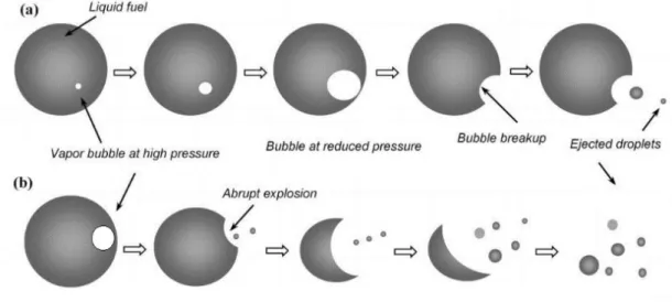
1.2.2.8. Physics of puffing and micro explosions
The combustion of a highly multicomponent fuel or of an emulsion of two fuels with different volatility usually leads to the occurrence of puffing, and micro explosions. Figure 1.8 illustrates the occurrence of puffing and micro explosions. Initially, small gas bubbles start to nucleate inside the fuel droplets, and the pressure inside the vapor bubble becomes higher than the ambient pressure. The tiny bubbles coalesce into a relatively larger bubble due to the internal circulation inside the droplet, and thus larger gas bubbles are formed. Since the nucleation sites are dependent on the proportion of higher volatile components, a lower proportion of the higher volatile component results in fewer nucleation sites and, hence, less coalescence of tiny bubbles. Therefore, the bubble cannot grow further and eventually breaks apart resulting in the ejection of small secondary droplets. The breakup of a relatively smaller bubble without droplet breakup is referred to as puffing. The breakup of the inner gas bubble can lead to the
breakup of the fuel droplet, leading to the ejection of the smaller secondary droplets and volatiles. The complete breakup is called micro explosion and can be associated with a flame involving the ejected material [22]. The appearance of puffing and micro explosions during the overall droplet lifetime can also be referred to as disruptive burning.
Figure 1.8: Sequence regarding nucleation, bubble growth, and the breakup of parent droplet: (a) Schematic of puffing; (b) Micro explosions.
The initiation, development, and effect of these processes on the multi-component fuel droplet combustion need to be further comprehended. Considering the microscopic size of the fuel droplets within the real spray, studying these processes during spray combustion is quite challenging. Alternatively, these processes can only be extensively investigated using an isolated fuel droplet undergoing combustion. Magnified visualization of the droplet surface and the surrounding environment during combustion will provide more in-depth details about the occurrence of puffing and micro explosion.
1.3.
Alternative jet fuels
In this section, the topic of alternative fuels in the aeronautical sector is addressed. In non-aviation sectors, the use of alternative fuels with different properties or phases is allowed through a small and justified engine upgrade (for example, in the automotive industry), but in the aviation sector there are great restrictions to the use of alternative fuels for various reasons. Firstly, an optimum operation of gas turbines requires specific and well-defined fuel properties due to the extreme conditions of operation and conditions of combustion, which reduces the range of suitable candidate fuels to a restricted group of liquid hydrocarbon blends. Moreover, the alternative fuel must be interchangeable with the present jet fuel, and therefore compatible with the existing fleet. If not, airports would have to provide different qualities of fuels, introducing logistic issues, and limiting the movement of the aircrafts towards the
14
destinations where the alternative refueling is available [7]. Because of this second requirement, alternative fuels for aviation are also referred to as “drop-in” fuels. Fossil fuel prices are becoming more volatile day by day. So, it is essential to introduce alternative aviation fuels generated from renewable resources, especially biomass [23]. Alternative fuel is, therefore, suitable for aviation if it presents similar properties to conventional jet fuel, especially in terms of heating value and chemical properties [1]. So, in this chapter, a comparison between the available alternative jets fuels will be addressed in order to evaluate what kind of alternative jet is suitable for the aviation sector
.
Figure 1.9 shows different fuels in terms of their lower calorific value (LCV) as a function of their density. The figure includes different fuels ranging from conventional HC to alternative fuels obtained from different production methods and feedstocks. The horizontal line in Figure 1.9 represents a constant LCV of 42.8 MJ/kg. This value is currently in use as the minimum limit for aviation fuels. The two vertical lines in the figure show the current specification limits for jet fuel density of 775-840 kg/m3. In industrial gas turbines, fuelled by gaseous fuels, the Wobbe index has been used toidentify how far away from the design fuel an alternative fuel can be [23]. This considers the mass flow of the fuel, along with the amount of energy, that will be delivered through a given fuel delivery system to ensure that the fuel placement is correct. The Wobbe index,
𝐼
𝑤, is defined as:𝐼
𝑤=
𝐿𝐶𝑉
√𝑆𝐺
(1.6)Figure 1.9 also shows lines of constant Wobbe index. The Wobbe index needs to be modified for use with liquid fuels, being the situation more complex with the liquid fuel properties such as surface tension, viscosity, etc. having a substantial impact on fuel atomization [7].
A high LCV and high density would be most desirable for flight, offering the maximum energy release per volume and mass unit. A line has been added to the hydrocarbon group in Figure 1.9 showing the clear trade-off between high energy densities and low “mass” densities, and the upper limit to the desirability of high LCV and high-density using hydrocarbons. In general, heavy fuels have high energy densities and light fuels have high specific energy.
Figure 1.9: Lower calorific value as a function of density for a range of liquid fuels [7]. FAEs, commonly referred to as biodiesels, are most likely to be long-chain fatty acid ester groups derived from the transesterification of the triglyceride fat groups in the base oil. Figure 1.10 illustrates the transesterification process. The exact composition of this fuel is dependent on the composition of its original oil and how it's processed by the transesterification method. This fuel can be separated into two groups, by using methanol or ethanol will produce methyl (FAME), and by using ethyl esters it will produce (FAEE). The fuel properties depend on the raw material. Transesterification is potentially a comparatively cheap way of converting the large, branched molecular structure of the bio-oils into smaller, straight-chain molecules of the type required in regular diesel combustion engines. The use of biodiesel as aviation fuel does not require engine modification and infrastructure, but it presents some disadvantages that make FAE not suitable for the aviation sector. Its use reduces aircraft efficiency. The biodegradability of biodiesel may cause biological growth during storage which will affect stability [24]. The freezing point of biodiesel is very high compared to petroleum-based aviation fuel, which makes it insufficient for high altitude flights.
16
Figure 1.10: Transesterification process.
Fischer-Tropsch fuels (FT fuels) are hydrocarbon fuels, which are produced by catalytic conversion of syngas (CO and H2) [23]. Direct conversion of feedstock into a product (also known as liquefaction) is the most energy-efficient route, but presently commercial technology is based upon indirect conversion [23]. Figure 1.11 illustrates the FT process, which requires the production of syngas from a suitable feedstock that is then fed into a liquid conversion process. Depending on the feedstock used, the process is entitled ‘anything too liquid’ (XtL), where ‘X’ is ‘C’ (coal), ‘G’ (gas) or ‘B’ (biomass). Figure 1.11 shows the production method for this fuel. Firstly, syngas is produced through gasification of coal or biomass. The FT requires syngas and involves carbon chain building [25]. The synthetic crude yield is then upgraded by hydroprocessing–cracking and to produce a commercial product, thereby allowing the refinery to effectively design a fuel-based upon the desired chain lengths. The characteristic of the FT fuel is more independent of the feedstock and depends on the operating conditions such as temperature, pressure and syngas composition of the FT process. This is a major advantage because it is possible to control the output carbon numbers of the process and develop synthetic kerosene suitable for aviation [25]. However, this process is expensive, and the efficiency of the process varies from 25% and 50%, and these fuels tend to offer low power and low fuel economy due to less energy density. New fuel generations are being developed and several agencies such as DLR and NASA, have been developing and testing new generation FT fuels [26].
Figure 1.11: FT production process.
Synthetic paraffinic kerosene from hydroprocessing of esters and fatty acids (HEFA) is also referred to as hydroprocessed renewable jet fuel (HRJ) and, whenever animal biomass is not involved, as hydroprocessed vegetable oil (HVO). The suitable feedstock for HEFA production is fat biomass, rich in glycerides (mainly triglycerides), free fatty acids and fatty esters. The existing production plants mainly convert camelina oil, jatropha oil, and algae as energy crops, cooking oil and animal fat as side products of other industrial chains [23]. Figure 1.12 illustrates the productive process of HEFAs. After a first pre-treatment, aimed to remove impurities from
the feedstock, the biomass is refined through three main hydroprocessing stages. The objective of the hydrotreatment is to convert the biomass into paraffins. Oxygen is removed in presence of excess hydrogen via hydrodeoxygenation and decarboxylation processes, along with nitrogen, sulfur and residual metals. Selective hydrocracking is necessary to reduce the paraffins carbon number to a suitable value for aeronautical applications, namely C8-C16. The presence of this stage marks the difference between the production processes of hydroprocessed jet fuel and diesel fuel, which is referred to in this case as biodiesel. Then, in the isomerisation, the paraffins are converted into more compact isoparaffins, reducing the hydrocarbon blend freeze and flashpoints. These reactions are empowered by a multifunctional catalyst. The HRJs present several benefits such as being free of aromatics and sulfur and possess high cetane number, high thermal stability and low tailpipe emissions [27]. These fuels are stable for storage and resistant to microbial growth. HRJs are suitable for conventional aircraft engines without further engine modification and do not raise any fuel quality issues. These fuels avoid the chance of deposit formation in the engine and engine corrosion [28]. The fuel combustion is completely ash-free. HRJs are highly fit for higher altitude flights because of the better cold flow properties in comparison to other alternative fuels [29]. Additionally, the whole production process can easily be integrated into a conventional oil refinery, avoiding the development cost of a dedicated plant [1].
Figure 1.12: Hydroprocessing of vegetable oil.
1.4. Jet fuel
Aviation turbine fuel, commonly known as jet fuel (JF), is a distillate of the kerosene type, refined from conventional petroleum sources specially designed for gas turbine applications in the aeronautical industry. As gasoline and diesel fuel, JF is mainly composed of paraffins, naphthenes, and aromatics, along with small amounts of olefins and other compounds. The jet fuel composition is addressed in chapter 2.This wide variation in compounds found in jet fuel causes the combustion engineer difficulties when trying to model any combustion process. It is enriched with several additives, aimed to inhibit the hazard of static charges, reduce the oxidizing and corrosive potentials, increase the lubricity and improve the cold flow properties. The presence of additives, even though in parts per million, marks the main difference between jet fuel and kerosene [7].
18
The composition presents intermediate values for both vapor pressure and octane number, which result as the best values for the stable combustion under the extreme conditions of the turbine engine. Moreover, the high flash point reduces the explosion hazard, while the low freeze and wax points allow the high-altitude flight.
The main jet fuel grades for civil aviation applications are Jet A and Jet-A1. Jet A is only supplied for domestic flights in the USA, while Jet-A1 is adopted in the rest of the world. The two grades present similar properties, and mainly differ in the freezing temperature: -40 and -47 °C for the A and A1 grades, respectively.
The American standard specification ASTM D1655 [30] defines both A and A1 grades, while the European standard specification DEF STAN 91-91 [31] only defines the A1 grade, with slight and more stringent exceptions.
1.5. Overview
Only HVO (HEFA) and BTL (FT) fuels provide scope for GHG emissions reduction, with HVO offering reductions of 40% to 90% and BTL from 60% to 90% over their lifecycle, compared with conventional oil-derived fuels [32]. These results, however, assume 100% HVO or BTL which may not meet the specification in all properties [32]. It is important to mark the difference between the alternative jet fuel (the final mixture) and the alternative blending component. The standard specification for unconventional jet fuels − ASTM D7566 [33] − does not allow the direct use of the second. In order to further guarantee the fuel fitness, the alternative blend is constrained to consist of at least 50 %V of conventional jet fuel. The implementation of biofuels is supported by the growing supply of algal oil, HVO could constitute a significant share of transport fuels by 2030, with production in the order of 25 Mt/y, and in the order of 60 Mt/y by 2050 [32]. By comparing HVO with other alternative fuels it can be said that it provides one of the best solutions in terms of environmental impact, and in terms of backward compatibility as it was previously stated and in terms of production capability. So, for this work, a HVO with commercial name NExBTL, produced by NESTE, is used due to its properties and the potential to become an alternative to fossil fuels.
1.6. Objectives of this work
The objective of this work is to study the ignition and combustion characteristics of single droplets of jet-A1 (JF), hydroprocessed vegetable oil (NExBTL) and their mixtures in a drop tube furnace (DTF). Jet-A1 is used as a reference fuel for this work because it is the most common fuel used in the aviation sector, and HVO has been chosen due to its potential as a biofuel and because it is approved for blending with jet fuel in 50%/50% ratios. To evaluate the effect of blending HVO with jet fuel on the ignition and combustion characteristics of the
resulting mixtures, three mixtures of these two fuels were burned in a drop tube furnace with controlled wall temperature and oxygen concentrations.
Chapter 2
2. Materials and methods
This chapter describes the materials and methods used during the work. Firstly, the experimental setup is introduced. Next, the methods used are described. Finally, the properties of the fuels used are summarized.
2.1. Experimental setup
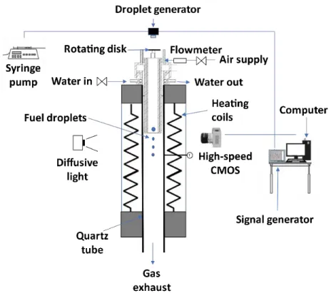
Figure 2.1 shows the experimental setup used in this study. It is composed by a DTF (drop tube furnace) and auxiliary equipments.
Figure 2.1: Schematic of the experimental setup.
2.1.1. Experimental facility
In order to study single droplet ignition and combustion, a new setup was projected and built. The DTF used in this experiment was designed for studies using solid biomass. So, a new injector for liquid fuels was developed. The water-cooling system and the air supply were designed similarly to the previous solid fuel injector for interchangeability between them in the same DTF.
22
The new injector was designed in CAD and is shown in figures 2.2, 2.3 and 2.4. During the design of the injector, several restrictions were considered. The main restrictions were in terms of inner diameter due to some fuel contamination in the inside walls. This creates safety issues due to the appearance of an updraft flame. The length of the tube is also a limitation because the droplet travel distance should be the minimum possible in order to minimize droplet heat up inside the injector and avoid ignition inside the injector. The injector was designed with a water-cooling system in order to maintain a good temperature for the operation of the setup without getting damaged and to avoid ignition inside the injector. The air supply is also a very important factor in order to have an airflow inside the drop tube with the minimum turbulence intensity possible, so a series of screens and nets where place to align the flow and reduce the maximum eddy diameter. A net with a 50 µm diameter and a honeycomb with 0.6 cm diameter and 6 cm length were used. The air supply was 5.7 l/min with a precision error of ±2%. The injector was built in the workshops of Instituto Superior Técnico using stainless steel 304. This material was chosen due to its resistance to corrosion and affordable price. It contains 18% chromium and 8% nickel. Figures 2.5 and 2.6 show the different parts of the injector. The injector was built in 3 separate parts in order to facilitate construction, cleaning and to allow different arrangements of screens and nets.
24
Figure 2.3: Technical draw of the injector − part 2 (dimensions are in mm).
Figure 2.5: Fully assembled injector.
26
2.1.2. Drop tube furnace
The DTF comprises an electrically heated coil and a vertical quartz tube with an inner diameter of 6.6 cm and a length of 82.6 cm. It can achieve wall temperatures up to 1200 ºC that are monitored by two thermocouples. The DTF has two opposed rectangular windows, with 2 cm width and 20 cm height, in the heating zone, which is 30 cm long. The temperature profiles inside the DTF were measured using 76 µm diameter R-type thermocouples placed on an appropriate probe. The probe is mounted on a mechanism that allows the thermocouple to move along the central axis of the quartz tube with a positioning accuracy of ±1 mm. Temperature readings were taken from a data acquisition board connected to a computer, being the acquisition time 30 seconds [34].
Figures 2.7, 2.8 and 2.9 show the ambient (air) temperature profile as a function of the vertical distance from the injector along the quartz tube for three DTF wall temperatures − the tip of the injector corresponds to the zero in the horizontal axis. Temperature flutuations can be viewed near the air supply entrance and the injector tip. This happens because the air takes some time to reach the DTF temperature, and due to interactions between the water-cooled injector tip and the hot air.
Figure 2.7: Ambient temperature as a function of the vertical distance from the injector tip at 900 ºC.
Figure 2.8: Ambient temperature as a function of the vertical distance from the injector tip at 1000 ºC.
Figure 2.9: Ambient temperature as a function of the vertical distance from the injector tip at 1100 ºC.
28
2.1.3.Droplet generator system
Figure 2.10 shows a schematic of the droplet generating system.
Figure 2.10: Schematic of the droplet generating system [35].
The droplet generator (a) is located on the top of the installation in the injector system, aligned with the DTF and at 50 mm between the axis of the injector and the tip of the injector. The generator was manufactured by TSI and is a Monosize Droplet Generator 100. It produces a stream of uniform size drops in the range of 50 µm to 300 µm, which is a good compromise between actual sizes in practical applications and a good accuracy of the experimental results. Figure 2.11 shows the principle for producing a mono-size droplet stream, where S represents the inter droplet distance, dd represents the droplet diameter, vd represents the droplet
velocity, and λdis represents the wavelength of the excitation signal. It relies upon the principle
of applying a constant periodic excitation to a laminar liquid jet, which causes surface waves to form and grow as the jet slows down. Breakup into a single droplet per surface wave period thus occurs. This is an established technique of mono-size droplet generation and is commonly used for fundamental droplet studies like vaporization, combustion, levitation, and surface interaction. Droplets were produced with an initial diameter of 155 ± 5 µm, which is an acceptable compromise between actual sizes in practical applications and experimental constraints in order to get good accuracy with the measurements. The mono-size stream of droplets was injected along the axis of the quartz tube, coaxially with the airflow produced by the air supply.
Figure 2.11: Schematic for the method for producing a monosize stream of droplets [35]. Figure 2.12 shows the devices that support the droplet generator, comprising a syringe pump and a signal generator. The excitation frequency was produced by a Fluke PM5136 frequency generator (b), that can produce a square wave with an amplitude of 20 Vpp and a frequency range of 0.1-5 MHz, which fits perfectly in the requirements of the MDG 100.
Figure 2.12: Photograph of the a) syringe pump, and b) signal generator.
In order to provide a liquid flow, a syringe pump NE-1000(c) is used, which provided the compatible flow rate with the MDG. A glass syringe was used to ensure that the properties of
a)
30
the fuel are maintained. It is possible to approximately calculate the droplet diameters using the following relation:
where D is the droplet diameter, Q is the volume flow rate, and f is the excitation frequency. The diameter of the droplets in micrometers can be represented by:
𝐷(𝜇𝑚) = 317𝑄(𝑚𝑙/𝑚𝑖𝑛) 𝑓(𝐾𝐻𝑧) 1 3 ⁄ (2.2)
In this study, a frequency of 1.5-2.8 kHz , a flow rate of 0.8-1.6 ml/min and two different pinholes with 100 and 200 µm were used. The reason for using different values for flow rate and frequency is because the different fuels present different excitation regimes and different flow properties. With this frequency range it was possible to achieve the required diameter with a staple mono-size stream. The MDG is only capable of producing stable streams with an inter droplet space of 7 droplets, which is not enough to obtain the phenomenon of single droplet ignition. This is due to droplets interact aerodynamically with each other’s wake. Consequently, a rotating disk had to be designed in order to increase the inter droplet space, as shown in Figure 2.13. The disc was coupled to an electric motor and a DC power supply that permitted a voltage from 3 V to 12 V. With this power supply it is possible to regulate the rotating disc angular velocity. The disk was placed between the droplet generator and the entrance tip of the injector. This technique has already been applied by other authors [36]. In the beginning, the jet was directed into a recipient until the droplet stream is stabilized. Afterward, the disc was rotated, and the droplets could penetrate the slot for a short time depending on the rotating velocity. With this solution, it was possible to obtain just one droplet per frame and guarantee a single droplet phenomenon.
𝐷 =
6𝑄
𝜋𝑓
1 3 ⁄ (2.1)Figure 2.13: Representation of the a) droplet generator, and b) rotating disk.
2.2. Droplet imaging technique and acquisition system
Backlighting imaging is the chosen technique for this work. This method is used for tracking droplet size, position and other kinds of interactions such as droplet impingement. Figure 2.14 shows the typical arrangement of an installation setup using this technique. It consists of the alignment of a light source and an imaging system; then a test object is placed between the lighting and the imaging system. The light source makes the droplet boundaries sharper and ensures that they are easily outlined. As a result, it increases the accuracy of the tracking of droplet size and lifetime. For these reasons, this method has been implemented in a huge number of studies involving droplet characterization. One of the most important factors in the setup is the spatial resolution micron/pixel − the spatial resolution of the image is the ratio of the physical length to image pixels. This is one of the main parameters that affect the accuracy of the results and the size of the image field of view. In order to achieve a high resolution, a microscopic lens must be used. However, this technique only permits tracking the droplet surface boundaries, but not much help for droplet interior tracking.
32
Figure 2.14: Schematic of the backlighting image setup.
Figure 2.14 shows the image acquisition system, which consists of a high-speed camera, a high magnification lens, a homogenous light source and a computer to control the camera and save the images for further image data analysis. The camera used was a CR600x2 from Optronics with a maximum resolution of 1280×1024 at 500 fps and capable of going up to 6000 fps with a resolution of 256×256. During the experiments, a frame rate of 1000 fps was used, which decreased the resolution to 1280×500 and a shutter speed of 8000 s-1. This shutter speed was
selected because an increase in its value would mean a reduction in the image brightness. A high magnification lens Zoom 6000® Lens System was attached to the high-speed camera. This is a modular system that permits the magnification of a traditional microscope at a working distance of 300 mm. It is composed of 6.5×Zoom, 12 mm FF, a 0.25× lens attachment and a 2.0× short adapter, with a magnifying range of (0.35-2.25), which makes possible to increase the spatial resolution of the image up to 8.2 µm/pixel. The setup requires background homogeneous illumination to intensify the contrast and to improve the visualization of the images. This illumination was parallel to the droplet falling plane. To provide uniform illumination, a diffusion glass was placed in front of the LED projector. Calibration of the IAS was done before every set of measures with a reference with 76 µm diameter that was placed in the focal plane. Afterward, the scale pixel/mm was determined to allow the treatment of data. This imaging method not only gives information about the droplet size and motion but also about the flame location. Additionally, for each experimental condition, a minimum of 30 single droplets were analyzed.
Figure 2.15: Image acquisition system.
2.2.1. Edge detection algorithm
It is necessary to develop a tool that permits to obtain several parameters from the images taken during the experiment such as droplet velocity, signal intensity, droplet area, droplet diameter. Due to this, an edge detection algorithm was used, which enables the acquisition of these parameters.
Under the illumination field, the photographed fuel droplets appear in the recorded image as a darker element. Figure 2.15 shows a sample image of a burning 100% jet fuel droplet and the corresponding background image. There is a sharp transition from light gray to darker gray pixels near the droplet surface, a pronounced gradient of intensity values characterizing the outline region. Near the droplet flame, changes in brightness intensity exist and it is possible to characterize the flame intensity and shape. The properties of each frame are calculated and stored in order to evaluate how this parameter change during evaporation and combustion.
Figure 2.16: 100% JF droplet burning at 1100 ºC.
To determine the drop outline region, it is considered both the brightness difference between the lighter background and the darker droplet and the local brightness gradient. The brightness gradient is determined using four connected pixels in the vertical and horizontal. Both
![Figure 1.1: Expected growth for aircraft global fleet [3].](https://thumb-eu.123doks.com/thumbv2/123dok_br/18944546.939988/27.892.154.801.636.967/figure-expected-growth-aircraft-global-fleet.webp)
![Figure 1.2: Schematic showing the ideal and real combustion processes for aero-engines [3]](https://thumb-eu.123doks.com/thumbv2/123dok_br/18944546.939988/30.892.123.738.203.462/figure-schematic-showing-ideal-real-combustion-processes-engines.webp)
![Figure 1.5: Measured ignition delay time versus droplet diameter for n-heptane droplets for different ambient gas temperatures [17]](https://thumb-eu.123doks.com/thumbv2/123dok_br/18944546.939988/35.892.226.697.109.491/figure-measured-ignition-droplet-diameter-droplets-different-temperatures.webp)
![Figure 1.6: Schematic of Inter droplet interaction [19].](https://thumb-eu.123doks.com/thumbv2/123dok_br/18944546.939988/36.892.136.728.497.828/figure-schematic-inter-droplet-interaction.webp)
![Figure 1.7: The influence of droplet spacing in the Ignition delay time[].](https://thumb-eu.123doks.com/thumbv2/123dok_br/18944546.939988/38.892.228.624.180.730/figure-influence-droplet-spacing-ignition-delay-time.webp)
![Figure 1.9: Lower calorific value as a function of density for a range of liquid fuels [7]](https://thumb-eu.123doks.com/thumbv2/123dok_br/18944546.939988/41.892.186.762.112.499/figure-lower-calorific-value-function-density-range-liquid.webp)