Methodology and Experimental T
echniques |
Note
hydraulic conductance in plants
Luciano Pereira (*); Paulo Mazzafera
Departamento de Biologia Vegetal, Instituto de Biologia, Universidade Estadual de Campinas, Caixa Postal 6109, 13083-970 Campinas (SP), Brasil.
(*) Corresponding author: [email protected]
Received: July 21, 2012; Accepted: Dec. 6, 2012
Abstract
Plant yield and resistance to drought are directly related to the efficiency of the xylem hydraulic conductance and the ability of this system to avoid interrupting the flow of water. In this paper we described in detail the assembling of an apparatus proposed by Tyree et al. (2002), and its calibration, as well as low cost adaptations that make the equipment accessible for everyone working in this research area. The apparatus allows measuring the conductance in parts of roots or shoots (root ramifications or branches), or in the whole system, in the case of small plants or seedlings. The apparatus can also be used to measure the reduction of conductance by embolism of the xylem vessels. Data on the hydraulic conductance of eucalyptus seedlings obtained here and other reports in the literature confirm the applicability of the apparatus in physiological studies on the relationship between productivity and water stress.
Key words: water, conductivity, cavitation, embolism.
Um aparato de baixo custo para medição da condutância hidráulica do xilema em plantas
Resumo
A produtividade das plantas e a capacidade de resistência à seca estão diretamente relacionadas com a eficiência da con -dutância hidráulica do xilema e a capacidade desse sistema em evitar a interrupção do fluxo de água. No presente trabalho, detalha-se a montagem de um aparato proposto por Tyree et al. (2002), e sua calibração, bem como adaptações com peças de menor custo que tornam o aparelho acessível a qualquer um trabalhando nesta linha de pesquisa. Esse aparato possibi -lita medir a condutância de partes do sistema radicular ou da parte aérea (ramificações radiculares ou ramos), ou em todo o sistema, no caso de plantas de porte pequeno ou plântulas. O aparato também pode ser usado para medir a redução da condutância pela embolização dos vasos do xilema. Medições de condutância hidráulica feitas em plântulas de eucalipto e outros trabalhos encontrados na literatura confirmaram a aplicabilidade desse aparato em estudos fisiológicos de produtivi -dade relacionada ao estresse hídrico.
Palavras-chave: água, condutividade, cavitação, embolia.
The productivity of plants is directly related to the ef-ficiency of their xylem conduit network to transport water and nutrients (Brodribb, 2009). However, for more efficient hydraulic conductance, carbon in-vestments are required for the hydraulic system for-mation, which can reduce growth rates (Maherali et al., 2004). Moreover, the development of highly negative water potentials increases the probability of bubble formation in the xylem, which interrupts the flow through vessels and may reduce the rate of photosynthesis and, consequently, growth (Tyree and Sperry, 1989). To avoid this problem, the hydraulic system can be more resistant to cavitation, and great-er resistance is associated with lowgreat-er porosity of the
membrane between xylem vessels, which, in turn, re-duces water flow efficiency (Hacke et al., 2006).
coupled to the outlet of the plant segment, measuring the mass of solution that emerges per second.
An apparatus for measuring the xylem hydraulic conductance of the entire shoot or root was proposed by Kolb et al. (1996), which uses a suction tube via a vacuum pump to generate ΔP. This vacuum tube applies suction to the entire shoot system with its various “out-lets” (the leaves and branches cut), whereas the “inlet” (the trunk base) is connected to the solution arranged on a balance. Conversely, the flow direction is reversed for the roots, in which the radicular branches are suctioned as “outlets” and the “inlet” is the connection with the stem. Thus, this apparatus is inverted compared with the appa-ratus proposed by Sperry et al. (1988), which considers the mass of the solution suctioned through the branch or root. The reverse flow, in relation to the flow in intact plant, has no effect on the conductance (Sperry et al., 1988; Kolb et al., 1996).
To eliminate bubbles in the xylem, thus enabling the maximum conductance to be measured, Kolb et al. (1996) proposed a system connected to the apparatus by a three-way valve near the connection with the plant, con-sisting of a cylinder of compressed air that provides 100 to 175 kPa pressure on a bladder containing the solution used in the apparatus. The air pressure on the bladder propels the solution through the plant vessels without al-lowing air to enter into the system. Using such relatively high pressure, this treatment eliminates xylem bubbles when applied for defined periods of time and pressures, previously tested for each plant organ and species.
The entire plant parts (whole root or shoot system, or root ramifications and branches) have a degree of conduc-tance even without applying ΔP (Kolb et al., 1996). This requires that the mass suctioned under different ΔPs be measured to find the linear relationship between the mass and the pressure. The conductance at ΔP=zero is given by the point at which the line crosses the ordinate axis. The
conductance is the slope of this line. Five or more partial vacuum tension between 0 and 70 kPa are applied.
The need to measure the conductance at a variety of vacuum tension increases the time required to acquire the measurements for each plant. When also considering the time required to stabilise the balance, each point on the curve can require 3–5 minutes, which makes experiment with use a large number of replicates or treatments unfea-sible. To overcome this, Tyree et al. (2002) proposed the use of a Ultra-Low Flowmeter to decrease the time required for each measurement. By measuring the ΔP of a capillary tube using a pressure difference sensor, it is possible to estimate the flow, F, because the relationship between flow and ΔP of capillaries is calculated while calibrating the apparatus (see below the details of calibration). This sensor enables stable readings in only 4 seconds per point. The conductance is cal-culated as follows: k=ΔF/ΔP, where ΔF is the flow variation in relation to the variation of the vacuum pressure along the plant segment ΔP.
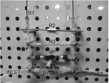
Tyree et al. (2002) recommend assembling the ap-paratus using eight-way valves (U- 06473-12, Cole-Parmer). With these valves, it is possible to connect three capillaries with different sizes and internal diameters (ID), R1=0.13 mm ID (718765, Macherey-Nagel) by 28 cm long; R2=0.18 mm ID (718760, Macherey-Nagel) by 28 cm; R3=0.18 mm ID by 9.5 cm. These different capillaries enable the measurement of different ranges of flow. Pressure difference sensors (PX26-005DV, Omega Engineering) and a tube with an internal diameter greater than 1.5 mm are installed between the valves for rapid adjustments of the zero pressure (Figure 1).
These eight-way valves allow each of the individual components of the apparatus to be opened and closed, which facilitates switching among capillaries, making zero pressure adjustments without detaching the plant. There are also special adapters for fixing the capillary tubes and rubber seals that prevent air from entering into the system.
The differential pressure sensor can be connected to a datalogger to record the data (OM-CP-VOLT101A-160MV, Omega Engineering). An interface and specific software (OM-CP-IFC200, Omega Engineering) are also necessary to connect the apparatus directly to the com-puter, which allows real time readings.
The sensor requires between 10–16 volts to oper-ate. Given that 5 mV V-1 in the sensor corresponds to 34.47 kPa, the software should be adjusted if the power is greater than 10 volts. If 12 V is used, 60 mV will return for 34.47 kPa. It is important the power source stability since the percentage of the voltage variation will be the percentage of the variation of the measurements, interfer-ing in the apparatus precision.
Tyree et al. (2002) suggest a compression fitting (U-06473-07, Cole-Parmer) to connect the apparatus to the plant. Thus, the plant is placed within a tube with the outlet positioned towards the vacuum pump. The inlet
Figure 1. Apparatus for measuring the hydraulic conductance
and outlet of the apparatus are connected via stiff plastic tubing that is at least 1 mm in internal diameter.
The apparatus is calibrated using a digital balance (ac-curacy of 0.1 mg). Water, or any other solution, is placed in a vial on the balance and in contact with the inlet tube from the apparatus. The outlet tube from the apparatus is coupled to the vacuum pipe. The valves are opened only for the flow to pass through one of the capillaries. The vacuum pump is adjusted to a given pressure, and the mass suctioned in a given period is measured. The vacuum tension should be checked by a precision vacuum gauge during this phase of the calibration. Using the vari-ous ΔP measurements, it is possible to generate a linear relationship between mass and pressure for each capillary. For example, Figure 2 shows the calibration performed for our apparatus.
During the calibration and use of the apparatus, the levelness between the inlets, i.e., the level of the solution, and the outlet, where the plant is attached, should also be examined. A siphoning effect can occur with a ΔP of 1 kPa for each 0.1 m of height difference. The levelness can be checked by stabilising the balance or leaving the “bypass” tube open.
Although laborious, it is possible to assemble a less ex-pensive apparatus. We estimate a cost of U$480 to mount this apparatus, versus U$1600 without the replacement of parts. Not including the pump pressure and the bal-ance. To do so, we replaced the two eight-way valves with eight three-way valves (three-way stopcock, Embramed) commonly used in hospitals for intravenous therapy. These valves have a quick “luer-lok” connection, which enables sequential assembly (Figure 3).
To connect the capillary tubes, we used “luer-lok” adapters with silicon stops, which are also used in hospi-tals for intermittent injections (385111, Becton Dickison Infusion Therapy Systems, Inc.). We filled these adapters with a silicone gel to ensure that they were sealed. The in-let, outlet and “bypass” (stiff tubing: 2.2 mm inside diam-eter [ID] and 3.1 mm outer diamdiam-eter [OD]) tubes were connected using sections of flexible silicon tubing (3 mm ID and 5.2 mm OD).
To connect the apparatus to the plants, we used the same flexible silicone tubing described above, although the diameters of the seedlings used in our experiments were slightly larger than the tubing. To ensure a proper seal, we used sections of longitudinally matched silicone tubing (4.9 mm ID and 9.7 mm OD) and fasteners with removable plastic clamps (RZ-06832-02, Cole-Parmer). Depending on the size of the plants and type of clamp used to ensure a proper seal, tubing with different diam-eters can be adapted for use.
For the system to remove bubbles from the xylem, the compressed air cylinder and bladder compression system were replaced with a syringe coupled to an air compres-sor. The pressure was verified in the manometer of the air compressor (Figure 4).
The syringe plunger was cut to reduce its length and allow connection with air compressor (see detail in Figure 4). The 60 mL syringe barrel (309663, Becton Dickison Infusion Therapy Systems, Inc.) was connected to a tube coming from the air compressor enabling us to regulate the pressure on the solution to be injected into the plant. A three-way valve was connected to replenish 100
80 60 40 20 0
400 300 200 100 0
1200 1000 800 600 400 200 0
0 10 20 30 40 50 60 0 10 20 30 40 50 0 10 20 30 40 50 60
kPa kPa
kPa y=0.8293x
R2=0.999
y=7.5029x R2=0.999
y=22.191x R2=0.999
R1 R2 R3
mg min
-1
mg min
-1
mg min
-1
Figure 2. An example of the calibration performed for our “ultra-low” flowmeter for the three capillaries (R1=0.13 mm ID by 28 cm long;
R2=0.18 mm ID by 28 cm; R3=0.18 mm ID by 9.5 cm) measured using a digital balance.
Figure 3. Alternative assembly for an “ultra-low” flowmeter
the syringe with the solution as needed. This system was connected to the apparatus near the connection with the plant via another three-way valve.
The use of this apparatus and its conductance mea-surements enables us to compare the different charac-teristics of the plant with its hydraulic system. With few adaptations in the apparatus, the method with vac-uum can be applied to measure the root conductance,
stem and leaves, as shown by several authors (Kolb et al., 1996; Sack et al., 2002; Tyree et al., 2002; 2003; Kursar et al., 2009; Melcher et al., 2012). We have also successfully used our assembled appara-tus to determine the conductance in stems, roots and leaves of other species like coffee and citrus (unpub-lished data). As an example, we measured the conduc-tance in Eucalyptus sp. (n=7, 120 days old seedlings, length 39±4 cm), and regressed it against the leaf area (Figure 5). All leaves of each seedlings were cut in the petiole portion and measure of the total area was made with area meter (3100, Li-cor, Inc.). In this case the solution used was a 10 mM KCl, which was previously degasified and filtered in 0.22 µm filters.
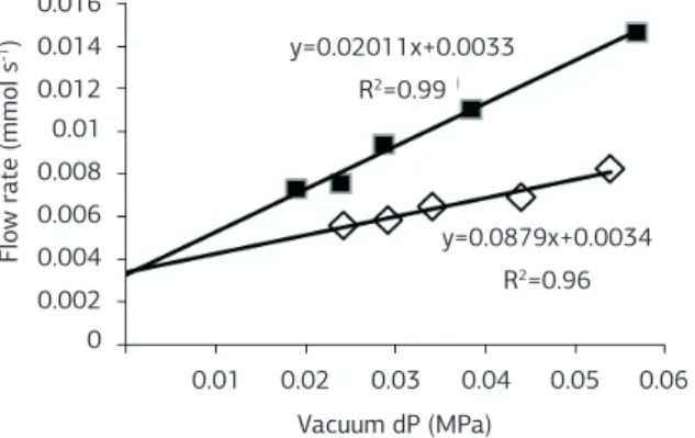
In another example, we evaluated the loss of con-ductance due to the cavitation of vessels. Cavitation resistance can be evaluated by comparing the conduc-tance measurements of a desiccated plant at different water potentials in xylem and measurements after the treatment to remove bubbles from the xylem (Sperry et al., 1988). The difference between the maximum conductance (after treatment) and conductance of the desiccated plant (initial) can be represented as the percentage loss of conductance. In Figure 6, we show the measurements in a Eucalyptus sp. plant that exhib-ited an approximately 60% loss of conductance un-der a leaf water potential of -2.5 MPa, measured with a pressure chamber (PMS 1000, PMS Instrument Company). We used a degasified and filtered 10 mM KCl solution.
ACKNOWLEDGEMENTS
The authors thank Dr Melvin T. Tyree for supplying the peek tubing used in the apparatus. This work was par-tially supported by Fundação de Amparo à Pesquisa do Estado de São Paulo. P.M. thanks Conselho Nacional de Desenvolvimento Científico e Tecnológico (CNPq-Brazil) for a research fellowship.
REFERENCES
BRODRIBB, T.J. XYLEM HYDRAULIC PHYSIOLOGY: The functional backbone of terrestrial plant productivity. Plant Science, v.177, p.245-251, 2009.
HACKE, U.G.; SPERRY, J.S.; WHEELER, J.K.; CASTRO, L. Scaling of angiosperm xylem structure with safety and efficiency. Tree Physiology, v.26, p.689-701, 2006.
KOLB, K.J.; SPERRY, J.S.; LAMONT, B.B. A method for measuring xylem hydraulic conductance and embolism in entire root and shoot systems. Journal of Experimental Botany, v.47, p.1805-1810, 1996.
Figure 4. A simplified apparatus for applying the solution under
pressure. The tubing is connected to an air compressor with a manometer to regulate the pressure. The picture shows the apparatus assembled for disconnected use of the flowmeter.
Figure 5. Hydraulic conductance (K) relative to leaf area of
Eucalyptus sp. seedlings.
0.01 0.02
0.2 1.2 1 0.8
0.4
0.025
0.005 0.015
0.6
0 0
K (mmol s
-1
M
Pa
-1)
Leaf area (m2)
y=60.213x+0.2297 R2=0.8558
Figure 6. Flow rates at different vacuum pressures in Eucalyptus sp.
seedling. The open symbols represent measurements at -2.5 MPa of plants dehydrated on the bench. The filled symbols represent measurements following the treatment to remove bubbles from the xylem. The conductance is calculated from the slope of the curves.
0.016 0.014 0.012 0.01 0.008 0.006 0.004 0.002 0
0.01 0.02 0.03 0.04 0.05 0.06 Vacuum dP (MPa)
F
lo
w rate (mmol s
-1)
y=0.0879x+0.0034 R2=0.96
KURSAR, T.A.; ENGELBRECHT, B.M.; BURKE, A.; TYREE, M.T.; EL OMARI, B.; GIRALDO, J.P. Tolerance to low leaf water status of tropical tree seedlings is related to drought performance and distribution. Functional Ecology, v.23, p.93-102, 2009.
MAHERALI, H.; POCKMAN, W.T.; JACKSON, R.B. Adaptive variation in the vulnerability of woody plants to xylem cavitation. Ecology, v.85, p.2184-2199, 2004.
MELCHER, P.J.; HOLBROOK, N.M.; BURNS, M.J.; ZWIENIECKI, M.A.; COBB, A.R.; BRODRIBB, T.J.; CHOAT, B.; SACK, L. Measurements of stem xylem hydraulic conductivity in the laboratory and field. Methods in Ecology and Evolution, v.3, p.685-694, 2012.
SACK, L.; MELCHER, P.J.; ZWIENIECKI, M.A.; HOLBROOK, N.M. The hydraulic conductance of the angiosperm leaf lamina: a comparison of three measurement methods. Journal of Experimental Botany, v.53, p.2177-2184, 2002.
SPERRY, J.S.; DONNELLY, J.R.; TYREE, M.T. A method for measuring hydraulic conductivity and embolism in xylem. Plant, Cell and Environment, v.11, p.35-40, 1988.
TYREE, M.T.; SPERRY, J.S. Vulnerability of xylem to cavitation and embolism. Annual Review of Plant Physiology and Plant Molecular Biology, v.40, p.19-38, 1989.
TYREE, M.T.; VARGAS, G.; ENGELBRECHT, B.M.J.; KURSAR, T.A. Drought until death do us part: a case study of the desiccation-tolerance of a tropical moist forest seedling-tree, Licania platypus (Hemsl.) Fritsch. Journal of Experimental Botany, v.53, p.2239-2247, 2002.