Ana Rita Pires Quintas
Dynamic modelling and analysis of
hydraulic forces in radial blood pumps
Ana Rita Pires Quintas
Dynamic modelling and anal
ysis of
h
ydr
aulic for
ces in r
adial blood pum
ps
Universidade do Minho
M.Sc. Dissertation
Integrated Master in Biomedical Engineering
Biomaterials, Biomechanics and Rehabilitation
Dissertation done under the supervision of
Professor Doutor João Paulo Flores Fernandes
Ana Rita Pires Quintas
Dynamic modelling and analysis of
hydraulic forces in radial blood pumps
Universidade do Minho
Acknowledgments
Developing this dissertation was one of the most challenging endeavours of my life. For this reason, the support I received from an amazing set of people during this period was invaluable for me. Therefore, I would like to extend a deep thank you:
To Professor Paulo Flores, for his end-to-end guidance, from helping me to choose my dissertation topic and for all the advice on the development of my dissertation.
To the Department of Mechanism Theory and Dynamics of Machines of the RWTH Aachen, for the incredibly warm welcome I received. I am grateful to them for accepting my request to develop my investigation in the institute and for making me feel at home from day one. In particular, I want to thank Ferdinand Schwarzfischer, my orientator, for helping me to overcome all the obstacles I faced, and for teaching me how to structure my approach to this investigation.
To ReinVAD GmbH, for their receptiveness and for letting me contribute to their project. In particular, I wanted to thank Hongyu Deng for always having the patience to shed light into all my doubts. Finally, I wanted to extend my deepest gratitude to Roland Graefe. For providing me with all the data and relevant materials I needed, for thoroughly explaining me how the ReinVAD LVAD worked and for saying “now this becomes interesting” whenever something unexpected happened to my research and I got worried.
To my friends in Portugal and in Germany who always told me to believe in myself and gave me support when I needed it. In special, I am grateful to my roommates in Aachen, Joana and Ana, for being my second family when I was away from home.
And last but must important, to my family, for all the support. Throughout my life they have been the pillar that supported me, and everything I ever achieved, I owe it to them. In particular I must deeply thank my mother, for always listening to me and putting a smile on my face when I needed it the most. I also want to give my deepest thanks to Tiago. Words cannot express how grateful I am for him being in my life and how much his help and support made this work easier.
Abstract
Dynamic modelling and analysis of hydraulic forces in radial blood pumps.
Cardiovascular diseases are the most frequent cause of death worldwide and one of the most important challenges that health systems across the world have to face.
Despite all their merits, conventional medication therapy and heart transplants present, respectively, important limitations of effectiveness and availability. As a result, cardiac mechanical assist devices have become a crucial and widely accepted option. The last decades witnessed the proliferation of a wide range of such devices, including the ReinVAD LVAD, which is a third generation blood pump currently under development by the Helmholtz-Institute for Biomedical Engineering and ReinVAD GmbH.
The present work focused on the dynamic analysis of the hydraulic forces acting on impellers of radial blood pumps. This approach was tailored to the ReinVAD LVAD, aiming to support its development. An analytical model of the axial hydraulic forces acting on this pump was developed and implemented in MATLAB® and SIMULINK®, allowing for the estimation of these forces under different scenarios and pump designs. As for the radial hydraulic force, a quick estimation methodology was adopted, which validated the initial assumption that the magnitude of this force would not be very relevant when compared to the one of the axial hydraulic force.
Applying this axial hydraulic force model, the two major variables of the pump operation - flow rate and rotation speed - were tested. The resultant axial hydraulic force magnitude was estimated, and its behaviour with changing conditions was discussed. Under a normal operating context, the magnitude of this force was estimated to be in the order of 0 to 1 N. Moreover, it was concluded that this force decreased in magnitude with increasing flows, while it increased in magnitude with increasing rotation speeds. To understand these results, the individual effects that affected the different components of the axial hydraulic resultant force were analysed in detail.
The conclusions of this study were found to match the existing literature on similar pumps. An additional validation of the model was performed, comparing its results with available CFD simulations of the ReinVAD LVAD. The predictions of the model and of the CFD simulations regarding the tendencies of the forces were found to be consistent in both simulations.
Resumo
Análise e modelação dinâmica das forças hidráulicas em bombas cardíacas radiais.
As doenças cardiovasculares constituem a principal causa de morte no mundo, apresentando-se como um dos mais críticos desafios enfrentados pelos sistemas de saúde.
Apesar de todos os seus méritos, a medicação convencional e os transplantes cardíacos apresentam importantes limitações, respetivamente de eficácia e disponibilidade. Estas razões levaram a que as bombas cardíacas se tenham tornado uma opção clínica amplamente aceite e crucialmente importante. Assim, as últimas décadas testemunharam a proliferação de um leque diversificado destes dispositivos, incluindo o ReinVAD LVAD, um dispositivo de terceira geração em desenvolvimento pelo Helmholtz-Institute for Biomedical Engineering e pela ReinVAD GmbH.
A presente investigação focou-se numa análise dinâmica das forças hidráulicas que atuam em bombas cardíacas radiais. Esta abordagem foi adaptada ao caso específico do ReinVAD LVAD, de forma a apoiar o seu desenvolvimento. Um modelo analítico das forças axiais hidráulicas que atuam nesta bomba foi assim desenvolvido e implementado em MATLAB® e SIMULINK®, permitindo estimar estas forças em diferentes cenários. Já a força radial hidráulica foi estimada de acordo com uma abordagem simplificada, validando a hipótese de que a sua magnitude é pouco relevante quando comparada com a da força axial hidráulica.
Aplicando o modelo desenvolvido para as forças axiais hidráulicas, foram testadas as duas principais variáveis do funcionamento da bomba – fluxo e velocidade de rotação. Estas simulações permitiram estudar a forma como as forças axiais hidráulicas reagem a alterações nestas duas variáveis. Concluiu-se que a magnitude da força resultante aumenta com reduções do fluxo e com aumentos da velocidade de rotação. Adicionalmente, estimou-se que esta magnitude esteja compreendida, para condições normais de funcionamento da bomba, entre 0 e 1 N. Os efeitos individuais e as diferentes componentes da força resultante foram analisados detalhadamente, e as conclusões deste estudo mostraram-se coerentes com a literatura existente.
Por último, o modelo foi validado através da comparação dos seus resultados com dados de CFD da ReinVAD LVAD, tendo-se concluído que os resultados eram coerentes em ambas as simulações.
Contents
Abstract ... v
Resumo ... vii
Contents ... ix
List of Abbreviations ... xiii
List of Symbols ... xiv
List of Figures ... xvii
List of Tables ... xxi
Chapter 1 - Introduction ... 1
1.1 Motivation ... 1
1.2 Scope and Objectives ... 2
1.3 Literature Review ... 3
1.4 Dissertation Overview ... 8
Chapter 2- Human Cardiovascular System and Cardiac Assist Devices ... 9
2.1 The Heart ... 10
2.2 The Blood ... 11
2.2.1 Composition of Blood ... 11
2.2.2 Macroscopic Rheological Properties of Blood ... 13
2.2.3 Hemolysis and Thrombosis ... 15
2.3 Heart Failure ... 16
2.4 Cardiac Assist Devices ... 18
2.4.1 Types of Cardiac Assist Devices ... 19
2.4.2 Hydrodynamic and Electromagnetic Bearings in Third Generation Blood Pumps ... 23
Chapter 3 - Dynamic Modelling and Analysis of ReinVAD LVAD ... 27
3.1 The ReinVAD LVAD ... 27
3.1.1 ReinVAD LVAD Description ... 28
3.1.2 Blood Flow in ReinVAD LVAD ... 31
3.2 Identification of Forces Acting on the Pump... 32
3.3 Axial Hydraulic Force Model ... 34
3.3.1 MATLAB and SIMULINK Implementation ... 42
3.4 Radial Hydraulic Force ... 43
3.4.1 Estimation of the Radial Force ... 45
3.5 Summary and Discussion ... 47
Chapter 4 - Results and Discussion ... 49
4.1 Scenario of Simulation ... 49
4.1.1 Simulation Conditions - Physiological Variables ... 49
4.1.2 Simulation Conditions – Pump Design and Dimensions ... 50
4.1.3 Simulation Conditions – Additional CFD Data ... 51
4.1.4 Description of the Simulations ... 52
4.2 Analysis of Results ... 53
4.2.1 Simulation with Variable Flow ... 53
4.2.2 Simulation with Variable Rotation Speed ... 60
4.3 Comparison with Available Data ... 65
4.4 Summary and Discussion ... 66
Chapter 5 - Conclusions and Future Developments ... 67
5.1 Conclusions ... 67
5.2 Future Developments ... 69
Appendix I - Auxiliary Calculation of Radial Hydraulic Force ... 79
Appendix II – SIMULINK® and MATLAB® Code... 81
Appendix II.I – MATLAB ® Code ... 81
Appendix II.II – SIMULINK ® Blocks ... 85
List of Abbreviations
AMB - Active magnetic bearing BiVAD - Biventricular assist device CFD - Computational fluid dynamics DOF - Degree of freedom
HF - Heart failure
IABP - Intraaortic balloon pump LVAD - Left ventricular assist device PID - Proportional integral derivative PMB - Passive magnetic bearing RBC - Red blood cell
RBP - Rotary blood pump
RVAD - Right ventricular assist device TAH - Total artificial heart
List of Symbols
Symbol Description Unit
b1 Blade inlet width m
b2 Blade outlet width m
b3 Volute inlet width m
b4 Blade inlet width with shrouds m
C Radial force coefficient -
c Absolute velocity m/s
c1m Meridional component of velocity in the impeller inlet m/s
c2m Meridional component of velocity in the impeller outlet m/s
cax_FS Axial distance between casing inlet and front casing wall (sax_FS + oax1) m
cax_RS Axial distance between casing inlet and rear casing wall (sax_RS + oax2) m
cu Absolute circumferential velocity m
dFS Diameter at front shroud m
dI Diameter at impeller m
dRS Diameter at rear shroud m
dV Diameter at volute m
f Frequency of the AC supply current Hz
Fax Axial hydraulic force N
Fb Buoyancy force N
FFS Axial hydraulic force on front shroud N
Fg Gravity force N
FG Gyroscopic force N
FHS Axial hydraulic force on shroud N
FI Inertial force N
FM Magnetic force N
Fm Momentum force N
FRS Axial hydraulic force on rear shrouds N
g Gravity acceleration ( g=9.8 m/s2) m/s2
H Pressure Head m
k̅ Mean rotation factor -
kWF Rotation coefficient of the fluid without flow through impeller sidewall clearances -
k̅FS Mean rotation factor at front shroud gap -
k̅RS Mean rotation factor at rear shroud gap -
mb Buoyancy mass kg
mR Rotor mass kg
Ns Synchronous speed rad/s
oax1 overlap between the volute and the impeller at front side m
oax2 overlap between the volute and the impeller at rear side m
P number of poles of the rotor -
p1 Pressure at impeller inlet Pa
p2 Pressure at impeller outlet Pa
Q Flow rate m3/s
q* Flow rate ratio -
QBEP Flow rate at best efficient point m3/s
Qlf Leakage flow m3/s
Qlf_RS Leakage flow in front shroud m3/s
r Radius m
Re Reynolds number -
rFS Radius at front shroud m
rI Radius at impeller m
rRS Radius at rear shroud m
rV Radius at volute m
sax_FS Axial distance between impeller front shroud and volute m
sax_RS Axial distance between impeller rear shroud and volute m
u Circumferential velocity m/s
u2 Circumferential velocity at the impeller outlet m/s
xFS Ratio of front shroud diameter and the impeller diameter ( dFS/dI) -
xRS Ratio of rear shroud diameter and the impeller diameter ( dRS/dI) -
β Angular velocity pf the fluid in the impeller sidewall clearances rad/s
ΔPim Static pressure rise in impeller (above impeller inlet) Pa
ε2 Angle between mean streamline and impeller axis at impeller outlet deg
μ Dynamic viscosity Pa.s
ν Kinematic viscosity (μ = ρ x ν) m2/s
ρ Density kg/m3
φlf Leakage flow coefficient -
List of Figures
Chapter 1
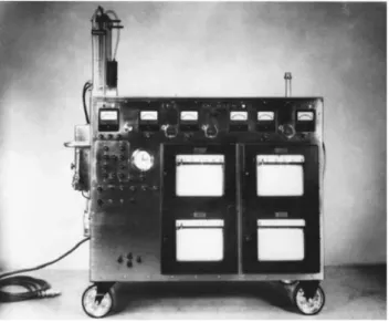
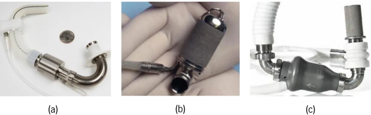
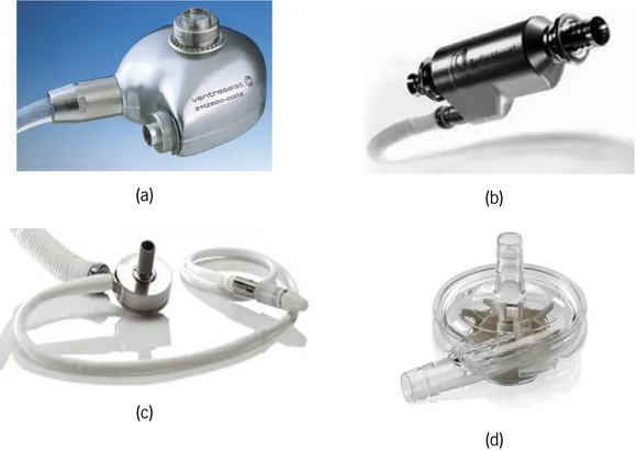
Figure 1.1 - Model II of the heart-lung machine used by Dr. John H. Gibbon in his first successful heart operation on May 6, 1953 (Hill 1982). ... 3 Figure 1.2 - Second generation pumps with successful application and implementation: (a) DeBakey VAD (Noon & Loebe 2010); (b) Jarvik 2000 (Jarvik Heart Inc. 2009); and (c) HeartMate II (Thoratec Corporation 2008). ... 4 Figure 1.3 - Third generation pumps with successful application and implementation: (a) VentrAssist LVAD (Jayanthkumar et al. 2013); (b) Berlin Heart INCOR (Berlin Heart GmbH 2009); (c) HeartMate III (Thoratec Corporation 2014) ;and (d) Levitronix CentriMag (Thoratec Corporation 2011). ... 5
Chapter 2
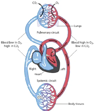
Figure 2.1 - An overview of the cardiovascular system and both systemic and pulmonary circulation. The blood is shown in blue when it deoxygenated and red when fully oxygenated; adapted from Whittemore (2009). ... 9 Figure 2.2 - Structure of the heart, and course of blood flow through the heart chambers; adapted from Guyton & Hall (2006)... 10 Figure 2.3 - Viscoelastic profile dependent of shear rate of normal human blood. Measurements were made at 2 Hz and 22 °C in an oscillating flow. In the bottom of the picture an illustration of the arrangement of RBC in each region is represented (Kowalewski 2005). ... 13 Figure 2.4 - Prevalence of heart failure by sex and age; adapted from Lloyd-Jones et al. (2009). ... 16 Figure 2.5 - Diagram of current solutions of cardiac assist devices; adapted from Reul & Akdis (2000). ... 20
Chapter 3
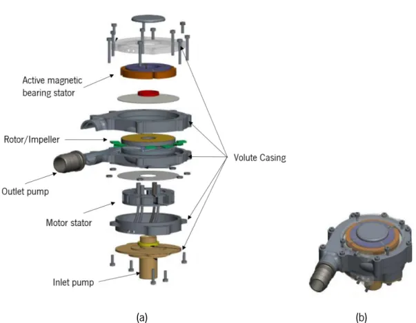
Figure 3.1 – (a) Exploded view of the ReinVAD LVAD; (b) Assembled view of the ReinVAD LVAD; adapted from Graefe & Deng (2015). ... 28 Figure 3.2 - Scheme of the single volute configuration: (a) Volute front view, with representation of volute throat and diffuser; (b) Volute cross section; adapted from Lazarkiewicz, Stephen Troskolanski (1965). ... 29 Figure 3.3 - 3D CAD illustration, with different materials represented of the internal elements of the pump: AMB; rotor/impeller; and motor stator; adapted from Graefe & Deng (2015)... 29 Figure 3.4 - Illustration of the impeller: (a) Closed impeller design; adapted from Lazarkiewicz, Stephen Troskolanski (1965) and (b) Meridional section of the ReinVAD LVAD impeller and volute casing. ... 30 Figure 3.5 - Meridional section of the impeller and volute casing, presenting the pressure distribution and axial hydraulic forces. ... 35 Figure 3.6 -Meridional section of the impeller and volute casing, presenting the main geometric variables. ... 36 Figure 3.7 - Main blocks of the resultant hydraulic force: axial hydraulic force on impeller shrouds and momentum force. ... 43 Figure 3.8 - Uniform pressure distribution around the impeller; adapted from Lazarkiewicz, S.Troskolanski (1965). ... 43 Figure 3.9 - Radial force for (a) low flow rates (q*<<1); and (b) high flow rates (q*>>1); ; adapted from Guelich et al. (1987). ... 45
Chapter 4
Figure 4.1 - CFD simulations: (a) Graph presenting the relationship between the pressure rise in impeller (mmHg) and the flow rate (l/min);(b) Graph presenting the relationship between the leakage flow (l/min) in each shroud and the flow rate (l/min): leakage flow in front shroud – red; leakage flow in rear shroud – blue. ... 51
Figure 4.2 - CFD simulations: (a) Graph presenting the relationship between the pressure rise in impeller (mmHg) and the rotation speed (rpm);(b) Graph presenting the relationship between the leakage flow (l/min) in each shroud and the rotation speed (rpm): leakage flow in front shroud – red; leakage flow in rear shroud – blue. ... 52 Figure 4.3 - Graph presenting the relationship between the axial hydraulic force (N) and the flow rate (l/min), based on the analytical model. ... 53 Figure 4.4 - Graph presenting the relationship between each component of the axial hydraulic force and the flow rate (l/min): momentum force - red (N) and the resultant force acting in the shrouds - blue (N), based on the analytical model. ... 55 Figure 4.5 - Graph presenting the relationship between each component of the resultant axial hydraulic force acting on the shrouds and the flow rate (l/min): Force acting on the rear shroud - blue (N) and force acting on the front shroud - red (N), based on the analytical model. ... 56 Figure 4.6 - Graph representing the local rotation factors along each radius ratio for the front shroud, for each flow rate – 1l/min (blue), 3l/min (red), 5l/min (black), 7l/min (blue dotted) and 9l/min (red dotted). ... 58 Figure 4.7 - Graph representing the local rotation factors along each radius ratio for the rear shroud, for each flow rate – 1l/min (blue), 3l/min (red), 5l/min (black), 7l/min (blue dotted) and 9l/min (red dotted). ... 58 Figure 4.8 - Graph presenting the relationship between the axial hydraulic force (N) and the rotation speed (rpm), based on the analytical model. ... 60 Figure 4.9 - Graph presenting the relationship between each component of the axial hydraulic force and the rotation speed (rpm): momentum force - red (N) and the resultant force acting in the shrouds - blue (N), based on the analytical model. ... 61 Figure 4.10 - Graph presenting the relationship between each component of the resultant axial hydraulic force acting on the shrouds and the rotation speed (rpm): Force acting on the rear shroud - blue (N) and force acting on the front shroud - red (N), based on the analytical model. ... 62
Figure 4.11 - Graph representing the local rotation factors along each radius ratio for the front shroud, for each rotation speed of the impeller– 1800 rpm (blue), 2100 rpm (black), 2400 rpm (red), 2700 rpm (blue dotted) and 3000 rpm (red dotted). ... 63 Figure 4.12 - Graph representing the local rotation factors along each radius ratio for the rear shroud, for each rotation speed of the impeller– 1800 rpm (blue), 2100 rpm (black), 2400 rpm (red), 2700 rpm (blue dotted) and 3000 rpm (red dotted). ... 64 Figure 4.13 - Graph presenting the relationship between the axial hydraulic force (N) and the flow rate (l/min) by the mathematical model developed – blue and the CFD data available for the ReinVAD pump – red. ... 65 Figure 4.14 - Graph presenting the relationship between the axial hydraulic force (N) and the rotation speed (rpm) by the mathematical model developed – blue and the CFD data available for the ReinVAD pump – red. ... 66
Appendices
Figure AII.1 - Main blocks of the resultant hydraulic force: axial hydraulic force on impeller shrouds and momentum force. ... 85 Figure AII.2 - “Momentum Force” subsystem block. ... 86 Figure AII.3 - “Resultant force in the shrouds” subsystem block. ... 86 Figure AII.4 - “Axial hydraulic force on front shroud” subsystem block... 87 Figure AII.5 - “Pressure component” subsystem block. ... 87 Figure AII.6 - “Rotation component” subsystem block. ... 87
List of Tables
Chapter 2
Table 2.1 - The constituents of human whole blood; adapted from (Bitsch 2002). ... 12 Table 2.2 - Application of mechanical circulatory support devices under different clinical scenarios. ... 19
Chapter 3
Table 3.1 - Results of radial force (N) vs flow rate (l/min). ... 46
Chapter 4
Table 4.1 - Rheological proprieties of the blood used for all simulations (Timms 2005; Fung 1993). ... 50 Table 4.2 - Dimension of the pump, according to Figure 3.6, in millimetres (mm) (Graefe & Deng 2015). ... 50 Table 4.3 - Description of each simulation. ... 52
Appendices
Table AI.1 - Dimension of the pump, according with Figure 3.6, in millimetres (mm). ... 79 Table AI.2 - CFD data static pressure rise in the pump (mmHg) for different flow rates in the pump (l/min). ... 80 Table AIII.1 - CFD data for leakage flow in rear and front shroud (l/min), and static pressure rise in the impeller (mmHg) for different flow rates in the pump (l/min). ... 89 Table AIII.2 - CFD data for leakage flow in rear and front shroud (l/min), and static pressure rise in the impeller (mmHg) for different rotation speeds of the impeller pump (l/min). ... 89 Table AIII.3 - CFD data of axial hydraulic force (N) for different axial positions (mm). ... 90
Chapter 1
Introduction
1.1 Motivation
Cardiovascular diseases (CVD) are the number one cause of death in the world, according to the World Health Organization (2014), being responsible for approximately 31% of all global deaths. In the particular case of heart failure (HF), it is estimated that approximately 23 million people in the world present this chronic conditions (Westaby & Frazier 2012). HF is a common clinical syndrome that affects the chambers of the heart, involving severe ventricular dysfunction, and ultimately leads to a reduction in cardiac output (Song et al. 2004; Couper 2001).
Cardiac medications used for conventional medical therapy for HF are frequently not sufficient, and, at any time, there is a limited number of donor hearts available. Against this background, mechanical cardiac assist devices (MCAD) are fast becoming an important accepted treatment strategy, often used as a bridge to transplantation and even as a long-term therapy (Bonow et al. 1980; Timms 2011; Song et al. 2004). The development of adequate and affordable MCAD is nowadays a major challenge for both academic researchers and companies.
The ReinVAD GmbH, in cooperation with RWTH Aachen University, is developing the ReinVAD Left Ventricular Assist Device (LVAD). The ReinVAD LVAD is a small, inexpensive, intelligently controlled radial ventricular assist device of the latest generation, which ensures stable and reliable circulatory support. At the present time, the LVAD is in prototype stage, and is expected to reach the market in 2018 (Graefe & Deng 2015).
In order to ensure optimal functioning of the ReinVAD LVAD, hydraulic forces acting on the rotor of the pump must be known and understood. A computational fluid dynamics (CFD) model has previously been prepared, which details the fluid dynamics of blood flow. However, despite being central for the development and functioning of the pump, this model presents some relevant limitations. Firstly, it does not detail the behaviour of each component of the hydraulic force separately. In fact, the CFD outputs a final resultant force, but does not detail a mathematical framework which explains how the change in each variable affects the final result, making it hard to predict how the resultant force will react to changes in relevant internal and external parameters.
Second, the CFD model is not capable of being integrated in the PID (proportional integral derivative) controller that has been developed for the pump in MATLAB®/SIMULINK®. Finally, the complexity of this model makes it unsuitable for the development of quick simulations, which are relevant when trying to test how the pump might react to a multitude of different scenarios.
The opportunity to develop a model that addresses the limitations of the CFD simulations, complementing them, motivates the present dissertation.
1.2 Scope and Objectives
The scope of the dissertation is the study of hydraulic forces acting on impellers of radial blood pumps. Thus, the major goal of this work is to develop a dynamic model of these hydraulic forces, and to apply it in the analysis of ReinVAD LVAD, in order to support the development of this device. To fulfil the purpose of this research, five objectives were outlined:
i. Develop a robust and flexible model of the axial hydraulic forces acting on the
ReinVAD LVAD; by creating a flexible model that allows for quick simulations, yields results
both for the resultant force and for each of the individual forces, and gives insight into the mechanisms that influence their behaviour. This research aims at creating an analytical tool that gives researchers the ability to quickly estimate how the axial hydraulic forces behave under different design and operation conditions of the pump.
ii. Analyse and discuss the behaviour of the axial hydraulic forces for the pump
current design; by simulating the response of each component of the axial hydraulic force to
changes in the two major variables of the pump operation (flow rate and rotation speed) and analysing the results. With this objective, this research aims at understanding and explaining the mechanisms that lead to the changes in the resultant force;
iii. Support the development of the pump controller; by implementing the model in MATLAB® and SIMULINK®, in order to integrate it in the pump controller in the near future; iv. Validate the developed model; by comparing the model results with available CFD
simulation data;
v. Assess if the hydraulic radial force is relevant for the ReinVAD LVAD; by evaluating the hypothesis, suggested by the reviewed literature, that this force would not be relevant.
1.3 Literature Review
In the last decades, mechanical cardiac assist devices have gained widespread acceptance as therapeutic instruments for the treatment of heart failure (Reul & Akdis 2000).
The first milestone in the field of mechanical cardiac assist devices occurred in the mid-twentieth century, with the development of the heart-lung machine by Gibbon J., Lillehei C., Kirklin J. and other investigators, Figure 1.1 (Hill 1982). The first clinical use of this technology, by Gibbon in 1953, successfully allowed for the correction of an atrial septal defect, by temporarily replacing the native heart while it underwent surgery (Argenziano et al. 1997; Bonow et al. 1980).
Figure 1.1 - Model II of the heart-lung machine used by Dr. John H. Gibbon in his first successful heart operation on May 6, 1953 (Hill 1982).
The next major progress was the intraaortic balloon pump (IABP), developed by Moulopoulos et al. (1962). This device was first applied surgically in 1967, in a patient with cardiogenic shock. Afterwards the IABP became widely used due to their usefulness in patients with reversible cardiogenic shock and as a bridge to transplantation (Argenziano et al. 1997; Bonow et al. 1980).
The first successful clinical use of a left ventricular assist device (LVAD), the class of device this investigation will address, was achieved by DeBakey et al. (1966). A patient with postcardiotomy syndrome was supported by an extra thoracic left heart bypass system for 10 days, after which the device was removed, and the patient survived (Argenziano et al. 1997; Bonow et al. 1980; Liotta 2002).
Meanwhile, several efforts to develop left ventricular assist devices (LVADs) were achieved. Initially, these devices were focused on reproducing the pulsatile outflow delivered by the native heart. These pumps, classified as first generation, presented reliability problems, by virtue of their mode of operation. In order to try to overcome these issues, continuous flow devices were developed, also called second generation pumps (Timms 2011).
Saxton & Andrews (1960) published the first article describing a continuous flow pump, presenting several potential advantages of the continuous flow blood pump over the positive displacement pumps. The authors referred as advantages the smaller size of the pumps, the lower power requirements, the minimum number moving parts and the extinction of valves. After that, several studies with continuous flow pumps were performed. Rafferty et al. (1968) developed a continuous flow blood pump, known as BioPump, with extremely low hemolysis rates, commercialized in 1976. Bernstein et al. (1974) published the results of a continuous flow ventricular bypass successfully implanted in a calf for 24h. Golding et al. (1979) reported favourable clinical results with the Medtronic pump (continuous flow pump) (Olsen 2000).
Since 1980, the progress of continuous flow blood pumps was so notary that several companies started the development of VADs. As a result, second-generation blood pumps as the DeBakey VAD (MicroMed), the Jarvik 2000 FlowMaker (Jarvik Heart), and the HeartMate II (Thoratec) have been implanted in selected patients for both bridge to transplantation and for destination therapy, Figure 1.2 (Reul & Akdis 2000).
(a) (b) (c)
Figure 1.2 - Second generation pumps with successful application and implementation: (a) DeBakey VAD (Noon & Loebe 2010); (b) Jarvik 2000 (Jarvik Heart Inc. 2009); and (c) HeartMate II (Thoratec Corporation 2008).
Literature reports of the successful use of continuous flow blood pumps encouraged investigators to develop a variety of pumps of this category (Olsen 2000). The third generation blood pumps resulted from additional investigation. These pumps eliminated wear by allowing the
suspension of the rotor without any mechanical contact. The earliest article describing a magnetically suspended impeller blood pump was published by Olsen et al. (1981). Akamatsu et al. (1992) also reported a magnetic suspended impeller pump that was in 1995 acquired by the Terumo Corporation. In 2001 the spin-off company Terumo Heart was created, in order to continue the development process, creating the DuraHeart VAD (Hoshi et al. 2006).
Many systems followed the successful application and implementation of the third generation pumps, including the VentrAssist LVAD (Ventracor), the MiTiHeart (MiTi Heart), the INCOR system (BerlinHeart), the MedQuest Heartquest (WorldHeart), the HeartMate III (Thoratec), and the Levitronix CentriMag (Thoratec), Figure 1.3 (Reul & Akdis 2000).
(a) (b)
(c)
(d)
Figure 1.3 - Third generation pumps with successful application and implementation: (a) VentrAssist LVAD (Jayanthkumar et al. 2013); (b) Berlin Heart INCOR (Berlin Heart GmbH 2009); (c) HeartMate III (Thoratec
Corporation 2014) ;and (d) Levitronix CentriMag (Thoratec Corporation 2011).
In magnetically suspended impeller blood pumps, the hydraulic forces need to be studied in order to support the design and operation of the magnetic levitation system (Japikse et al. 1997). The study of the hydraulic forces acting on the impeller includes the axial and the radial hydraulic forces, which are the subject of this investigation. Below several major studies of this subject are outlined.
Takami et al. (1997) investigated the axial force on the GYRO blood pump. The pump presented significant axial forces, due to the pump semi-open impeller, which created an asymmetric pressure distribution.
Allaire et al. (1996) described the development of a VAD prototype supported by an active magnetic bearing system. In the study the radial forces, including non-hydraulic ones (unbalanced forces, motor eccentricity magnetic forces, and others) were measured, reaching a maximum resultant radial force of 1.5 N.
Curtas et al. (2002) performed a CFD investigation of the axial forces acting on the HeartQuest LVAD. The axial force was simulated for two different impellers (CF3 and CF4). It was concluded that much more force acted on CF3, due to the fact that it produced more pressure and was larger, presenting more area on which the pressure could act.
Song & Wood (2004) performed a CFD study determining the axial and radial forces acting in a blood pump impeller. They concluded that the radial forces were small and negligible, contrarily to the axial force, which was revealed to be a critical parameter for magnetic suspension design. The tendency of the axial forces with the flow rate and rotation speed was also evaluated by Song & Wood (2004), which concluded that decreases of flow rate or increases in rotation speed led to increases in the magnitude of the axial force.
Untaroiu et al. (2005) compared measurements of the axial forces acting on an axial blood pump with CFD predictions, and found the CFD predictions to be accurate. The CFD model predicted that the axial force increased with the increase of rotation speed on the pump. The radial forces were found to be on the order of 10–3 N, and thus virtually insignificant.
Recently, Boehning et al. (2011) evaluated and discussed the dependency of the hydraulic radial forces and the volute type. The experimental tests concluded that the single volute had the lowest radial force (∼0 N), the circular volute yielded the highest force (∼2 N), and the double volute possessed a force of approx. 0.5 N.
Even with the successful application of blood pumps, there are still relatively few theoretical models for the hydraulic forces acting on the impeller, and most design improvements were developed through experimentation and practical experience. Therefore, for an improved literature review in this area, the behaviour of hydraulic forces in general radial pumps was also reviewed.
Many authors contributed to the research of the axial hydraulic force in radial pumps. Kazakov & Pelinskii (1970) evaluated the relationship between the axial force and the clearances. The study demonstrated that the axial force increased with an increase of the seal clearances, however it also concluded that in open impellers the increase of the axial force is several times faster than in pumps with closed impellers. Most recently, Gantar et al. (2002) performed a numerical flow analysis method to investigate the axial hydraulic force after the implementation of some pump design changes (wear rings). Comparisons of the original and modified design concluded that the generated forces under the new design were smaller.
As for the analytical approach to studying these forces, Lazarkiewicz, Stephen Troskolanski (1965), Lobanoff & Ross (1992) and ANSI/HI (1994) defined mathematical methods to predict axial forces. Most recently Gülich (2010) also defined a mathematical method to predict axial forces in radial pumps. This method of axial calculation accounts for the contribution of fluid momentum, and pressure distribution underneath and above the impeller.
The radial hydraulic forces were also studied by many authors. Flack & Allaire (1984) published a literature review of the measurement of both static and dynamic radial thrust and Guelich et al. (1987) provided an overview of the physical mechanisms that cause radial forces on an impeller, and also a review of the available techniques to measure them.
Adkins & Brennen (1988) investigated the radial forces that act on the impeller due to its interaction with the volute casing. The developed model requires a knowledge of the dimensions of the volute and impeller, and the total head rise across the entire pump. Comparisons between the predicted model and the experimental results were performed allowing the model to be validated.
Most recently, Baun & Flack (2003) performed a series of experiments in order to determine the effect of various impeller (four-blade and five-blade) and volute (spiral volute, concentric volute and double volute) combinations on radial force. The study concluded that the difference in the magnitude forces for the two different impeller in the same volutes was not significant. In the case of different volutes for the same impeller, the spiral volute presented the smallest magnitudes of the force, while the double volute presented the biggest magnitudes.
As for the analytical approach to calculate these forces, Stepanoff (1957) devised a method which enabled the pump designers to estimate the radial force on a radial pump. Biheller (1971),
Chamieh et al. (1985), Agostinelli et al. (1960), and Iversen et al. (1960) used this methodology, in order to compare the steady hydrodynamic forces on a radial pump impeller with empirical measurements and concluded that the model performed satisfactorily.
1.4 Dissertation Overview
This dissertation is divided in five chapters, addressing the scope and objectives outlined above.
The motivation for the dissertation is presented in chapter 1, together with the scope and objectives of the project. Moreover, the major literature on blood pumps and hydraulic forces acting on them are reviewed.
The background of the dissertation is outlined in chapter 2, where the human cardiovascular system, cardiac diseases and current blood pump solutions are discussed.
With this context in mind, chapter 3 details the previous developments of the ReinVAD LVAD, the technical elements of the device and the different forces acting on the pump. Having established this framing, a mathematical model of the axial hydraulic forces acting on the device is defined and implemented in MATLAB®/SIMULINK®. Furthermore, the radial hydraulic force acting on the pump is investigated and a simple estimation approach is implemented.
The results of the developed analytical model for the axial hydraulic force are presented in chapter 4, which is divided into three main sections. The first section describes each simulation and associated conditions (physiologic, design and dimensions). The second section analyses and discusses the performed simulations. Finally, the last section compares the developed mathematical model with available CFD data of the ReinVAD LVAD.
Finally, the conclusions of the dissertation are discussed in the chapter 5, and future developments are proposed.
Chapter 2
Human Cardiovascular System and Cardiac
Assist Devices
The cardiovascular system is comprised of four major components: blood, blood vessels, the heart, and the lymphatic system. Fundamentally, the function of the cardiovascular system is to service the needs of the body tissues; to circulate and transport nutrients, oxygen, hormones to the body tissues; and to transport waste products away from them. In short, to maintain an appropriate environment in all the body tissues for optimal survival and functioning of the cells (Zaret et al. 1992; Klabunde 2005).
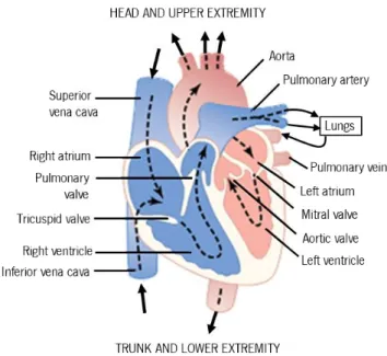
The cardiac circulation is divided into the systemic circulation and the pulmonary circulation, shown in Figure 2.1. Thesystemic circulationis responsible for transporting oxygenated blood from the left ventricle to the rest of the body (except the lungs), and returning deoxygenated blood back to the heart. Conversely, the pulmonary circulation transports deoxygenatedbloodaway from the heart into thelungs, and returns oxygen-rich blood back to the heart (Iaizzo 2005; Zaret et al. 1992; Klabunde 2005).
Figure 2.1 - An overview of the cardiovascular system and both systemic and pulmonary circulation. The blood is shown in blue when it deoxygenated and red when fully oxygenated; adapted from Whittemore (2009).
2.1 The Heart
The heart is a muscular pump that has two main functions: to collect blood from all the body tissues and to pump it to the lungs; and to pump the blood collected from the lungs to all tissues of the body.
The human heart, as is possible to see in Figure 2.2, is constituted of four heart chambers, each composed of cardiac muscle: two atria in the upper half of the heart; and two ventricles in the lower half. The ventricles pumps blood to all the organs and tissues and the atria receive blood as it circulates back from the rest of the body. Completing and separating the four chambers, the heart also presents a set of four valves. These valves are responsible for maintaining a one-way flow of blood through the heart. The atrioventricular valves (tricuspid and mitral) force blood to flow only from atria to ventricles. The semilunar valves (pulmonary and aortic) force blood to flow only from the ventricles out of the heart and through the great arteries (Guyton & Hall 2006; Zaret et al. 1992).
Figure 2.2 - Structure of the heart, and course of blood flow through the heart chambers; adapted from Guyton & Hall (2006).
The cardiac events that occur in a complete heartbeat from its generation to the beginning of the next beat are called the cardiac cycle. Each cycle includes a period of relaxation called diastole, followed by a period of contraction called systole. The rhythmic contraction and relaxation
of the chambers of the heart are controlled by electrical activity of the cells in the heart muscle (myocardium)(Guyton & Hall 2006; Zaret et al. 1992).
Diastole is the longer phase of the cycle, taking up approximately two-thirds of its duration. During this phase the tricuspid and mitral valves are open, and the pressures in the ventricles fall below those in the atria, propelling the blood from the atria into the relaxed ventricles. Note that, during the diastole, the aortic and pulmonary valves are closed since the interventricular pressure is lower than in the arterials (aorta and pulmonary artery) (Zaret et al. 1992; Klabunde 2005; Iaizzo 2005).
During systole, as soon as the ventricles fill in, the pressure inside them is larger than in the atria, hence the tricuspid and mitral valves close. As a result, the intraventricular pressure rises enough to force the pulmonary and aortic valves to open, and blood is forced out of the given ventricular chamber to the arteries (Zaret et al. 1992; Klabunde 2005; Iaizzo 2005).
In order to maintain the efficiency of the heart, contractions must occur at regular intervals and be synchronized; the valves must fully open and must not leak; ventricular contractions must be forceful (not failing); and the ventricles must fill adequately during diastole (Iaizzo 2005).
2.2 The Blood
2.2.1 Composition of Blood
Blood is a complex fluid that provides necessary substances, such as nutrients and oxygen to all of the body cells and removes metabolic waste products from them. The human blood mainly consists of a suspension of blood cells in plasma (Stoltz, J. F., Singh, Megha, Riha 1999). Table 2.1 shows the different constituents of blood and their respective concentrations.
The plasma is constituted by approximately 90% (w/w) water, containing 7 % (w/w) plasma proteins. Furthermore, it is widely considered to behave like a Newtonian (constant viscosity) fluid with a coefficient of viscosity about 1.2x10⁻³ Pa.s (Bitsch 2002; Fung 1993).
The blood cells include erythrocytes, leucocytes and platelets, all formed in bone marrow from a common stem cell, and each one contributes directly to blood viscosity. The erythrocytes, commonly named red blood cells (RBCs), are the blood cells with the most influence on blood viscosity. RBCs are disk shaped, with an average diameter of 7.6 µm and thickness 2.8 µm. These
cells have a primary role in the transportation of the oxygen in blood, since they carry haemoglobin. This protein allows blood to transport 40 to 50 times the amount of oxygen that plasma alone could carry. The leucocytes are required for the immune process to protect against infections and cancers, while the platelets play a determinant role in blood clotting (Iaizzo 2005; Fung 1993).
In an average-sized, healthy individual of 70 kg, the total volume of blood is approximately 5.5 L, while the haematocrit level (percentage of blood volume occupied by the RBCs) is 40−52% for men, and 35−47% for women. The high concentration of these cells in the blood, combined with their flexibility gives to blood an important non-Newtonian property (shear-thinning1) (Iaizzo 2005; Bitsch 2002; Fung 1993).
Table 2.1 - The constituents of human whole blood; adapted from (Bitsch 2002).
Composition Concentration Plasma Water 90% (w/w) Proteins 7 % (w/w) Albumins Globulins Fibrinogen 4.5 – 5.7 x 10⁻⁵ µL-1 1.3 – 2.5 x 10⁻⁵ µL-1 1.3 – 2.5 x 10⁻⁵ µL-1 Salts, dissolved gases, glucose, metabolites, nutrients Cellular Components
Red blood cells (7µm) White blood cells (8 - 20 µm) Platelets ( 1- 2 µm)
3.6 – 5.4 x 10⁶ µL-1 5 – 10 x 103 µL-1 1.5 – 4 x 10⁵ µL-1
2.2.2 Macroscopic Rheological Properties of Blood
Rheology is the science that studies deformation and flow of materials under applied forces. Thus, rheological properties are the properties that affect the deformation and flow of a material (Stoltz, J. F., Singh, Megha, Riha 1999; Tanner 2000).
Viscosity is one of the most relevant properties when discussing flowing fluids. From the macroscopic point of view, the viscosity of a fluid is a measure of its resistance to gradual deformation by shear or tensile stress (Stoltz, J. F., Singh, Megha, Riha 1999; Kowalewski 2005).
The shear rate, which is a measure of the deformation of the liquid, is defined according to Equation (2.1), where, vi is the velocity in the xi direction.
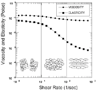
Blood is a viscoelastic fluid and Figure 2.3shown that the viscoelastic behaviour of normal human blood can be divided into three regions, according to the shear rate: Region 1 – Low Shear Rates, Region 2 – Mid-Shear Rates and Region 3 – High Shear Rates. As it can be seen inFigure 2.3the arrangement, orientation and stretching of the RBCs are responsible for changes in blood viscosity (Fung 1993; Bitsch 2002).
Figure 2.3 - Viscoelastic profile dependent of shear rate of normal human blood. Measurements were made at 2 Hz and 22 °C in an oscillating flow. In the bottom of the picture an illustration of the arrangement of RBC in each region
is represented (Kowalewski 2005). γ̇ = dvi
dxj +
dvj
Region 1 – Low Shear Rates
In the first region, the viscosity presents higher values and is approximately constant. At low shear rates, normal RBCs tend to aggregate in a space efficient manner, generating large aggregates of cells. These large agglomerates of blood cells cause disturbances in the laminar flow profile of the plasma. The aggregation properties of the RBCs control the viscoelasticity of the blood in this region, while the deformability is less relevant (Bitsch 2002; Olesen 2003).
Region 2 – Mid-Shear Rates
In this region, the viscosity of blood is a decreasing function of the shear rate – the fluid displays shear thinning. This property is a result of the breakage of aggregates and a cell layering of the RBCs. The internal stress due to the pressure is enough to separate aggregated cells and, with the increase of the shear rate, the cells are oriented in the direction of flow. As result of the internal organization of the RBCs, friction reduces. In this region, red cell deformability influence overcomes influence of the aggregation properties in the control of viscoelasticity (Fung 1993; Bitsch 2002; Olesen 2003).
Region 3 – High Shear Rates
At shear rates above about 100 s−1, blood viscosity is reported to be a constant value, 3 x 10⁻³ – 4 x 10⁻³ Pa.s. With increasing shear, RBCs stretch or deform and align with the flow, which decreases the viscosity. For this reason, in this region, the viscoelasticity is controlled by the deformability of the RBCs. Due to the characteristics of this region, the blood is commonly
approximated to a Newtonian fluid in shear rates over than 100 s−1(Fung 1993; Bitsch 2002;
Olesen 2003).
Note that, viscosity is influenced by several factors besides shear stress, including the haematocrit (viscosity increases with increasing haematocrit levels), temperature (viscosity decreases with increasing temperatures) and some diseases (Fung 1993; Olesen 2003; Bitsch 2002; Stoltz, J. F., Singh, Megha, Riha 1999).
2.2.3 Hemolysis and Thrombosis
Hemolysis is the premature destruction of RBCs. RBCs normally live for approximately 115 days, afterwards naturally breaking down and being removed from the circulation (Franco 2012). However, some conditions cause their early destruction.
One of these conditions is the exposure to high shear rates for a prolonged period of time. Note, however, that since RBCs have a viscoelastic behaviour they can support high stresses for short exposure times without hemolysis (Leverett et al. 1972). Furthermore, hemolysis can also be caused by some diseases or be influence for some interaction of the cells with different surfaces
(Sowemimo-Coker 2002).
The breakage of RBCs causes the release of haemoglobin and other internal components. As result, hemolysis can be experimentally monitored by measuring the concentration of haemoglobin released to the extracellular medium (Deutsch et al. 2006).
A different condition is thrombosis, consisting in the formation of a blood clot, generally called thrombus. Typically, the blood clots are formed on an injured inner wall of a blood vessel and on contact with the surfaces of medical devices. The clot formation involves a complex cascade of enzymatic reactions (Fung 1993).
When blood contact with an injured vessel occurs, platelets adhere to its surface forming a larger aggregation. Afterwards, thrombin, the bottom enzyme of the coagulation cascade, converts fibrinogen (a blood protein) into fibrin, which in turn stabilizes the adhered platelets and forms a blood clot (Fung 1993; Galdi et al. 2008; Schima et al. 2008).
The formation of a thrombus and hemolysis are both frequent occurrences in blood pumps that should be avoided in order to ensure the success of the pump therapy. Thus, when designing a blood pump, the main factors that influence these two phenomena must be considered: the blood material interface, the surface topography, and the fluid mechanics. (Deutsch et al. 2006; Schima et al. 2008; Song et al. 2003).
2.3 Heart Failure
The heart is an efficient and durable pump. However, as any other electromechanical device, it can become less efficient or break down.
Heart failure (HF) is a major public health issue with a current prevalence of over 23 million worldwide (Westaby & Frazier 2012; Bui et al. 2011). The incidence of this condition has increased during the last decades and is expected to continue to grow. Projections estimate that by 2030, the prevalence of HF will increase 25% from 2013 estimates (Lloyd-Jones et al. 2009).
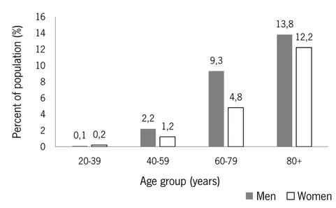
The main reason for this growth is the general aging of the population, since HF is age related. Figure 2.4 shows that the prevalence of HF increases with age, with approximately 13% of the American population over 80 years having HF (Lloyd-Jones et al. 2009).
Figure 2.4 - Prevalence of heart failure by sex and age in the USA in 2009 ; adapted from Lloyd-Jones et al. (2009). HF imposes a huge global economic burden with direct costs to countries healthcare systems and indirect costs to society (through morbidity, unpaid care costs, premature mortality and lost productivity). In 2012, the total costs are estimated at approximate $108 billion (with direct costs accounting for approximately 60% of the overall spend and indirect costs for the remaining 40%) (Cook et al. 2014).
Fundamentally, HF is a condition in which the heart has a reduced ability to pump enough blood to satisfy the needs of the body. Most commonly, HF involves the left ventricle, with right ventricular failure normally occurring secondary to left ventricular failure. In rare instances,
0,1 2,2 9,3 13,8 0,2 1,2 4,8 12,2 0 2 4 6 8 10 12 14 16 20-39 40-59 60-79 80+ Pe rcen t of pop ulat ion (%)
Age group (years)
however, the right side might fail on its own or in association with pulmonary disease (Guyton & Hall 2006; Klabunde 2005; Zaret et al. 1992).
Normally HF is classified according to the affected heart function, with the main types being systolic heart failure and diastolic heart failure. Frequently, patients present a combination of both systolic and diastolic dysfunctions. In case of systolic heart failure, the ventricles do not contract properly during each heartbeat, resulting in blood not being adequately pumped out of the heart. This dysfunction is characterised by a drop in cardiac output due to decreased contractility. Diastolic heart failure, on the other hand, is characterized by an impaired ventricular filling between each heartbeat (Klabunde 2005).
The most common symptoms of these conditions are shortness of breath, fatigue and swelling in the ankles, feet, legs and abdomen. In the early stage of the disease, patients start feeling tired and short of breath, while and after doing physical activities. In more severe stages, a patient may experience breathlessness even while at rest. Furthermore, the patient are likely to have significant pulmonary edema (a condition in which too much fluid builds up in the lungs). (Zaret et al. 1992; NHLBI Health Topics 2013).
Heart failure is usually a slow process, which can have several causes. The two major ones are: coronary artery disease and myocardial infarction (Klabunde 2005; Zaret et al. 1992).
The first one is responsible for a reduction in the coronary blood flow, which is the circulation of blood in the blood vessels of the heart muscle (myocardium). This reduction, in turn, leads to decreased contractility of the myocardium, since with a reduction in this blood flow, the levels of oxygen in the myocardium reduce too, causing myocardial hypoxia and impaired function (Guyton & Hall 2006; Klabunde 2005). The second, consisting of the partial death of heart tissue, reduces the efficiency of the heart, since the infarcted tissue does not contribute to the generation of mechanical activity of the heart. For this reason, the non-infarcted regions of the heart have to compensate for this loss of function, and with time the over-work demanded from these regions leads to a heart failure (Guyton & Hall 2006; Zaret et al. 1992).
Besides these main causes, heart failure can also be caused by valvular disease, long-standing hypertension, vitamin B deficiency, viral infections, congenital defects, chronic
arrhythmias, or any other abnormality that turns the heart into a hypoeffective pump (Klabunde 2005; Zaret et al. 1992).
The treatment for HF has mainly been aimed at improving quality of life of the patients, reducing the symptoms. Patients with this condition follow a significant regimen of cardiac medications, a therapy that sometimes is inefficient and fails. In fact, some patients become tolerant or develop side effects that prevent drug use. Moreover, in end-stage HF, the drug therapy is not enough, with these cases requiring a heart transplantation (Bonow et al. 1980; Song et al. 2004; Timms 2011). The International Society for Heart and Lung Transplantation estimates that, annually, the lives of approximately 50 000 persons in the world would improve with heart transplantation. Nevertheless, the number of available donor hearts only reaches 12% of the total needed amount, approximately 6 000 annually (Lund et al. 2014).
Considering the scarcity of donor hearts associated to the increase of HF cases, a necessity arose to explore alternative options. Hence, cardiac assist devices have become a promising alternative for the patients with HF. These devices can be employed to bridge a patient to heart transplant, to recovery, or indeed as a destination alternative (Park et al. 2005).
2.4 Cardiac Assist Devices
There are a large number of different mechanical devices to treat end-stage heart failure, appropriate for use in a number of different clinical scenarios. These devices can be categorized in four groups, depending on their main function: left ventricular assist device (LVAD); right ventricular assist device (RVAD); biventricular assist device (BiVAD) and total artificial heart (TAH). Given the higher prevalence of left ventricle failure, the LVAD became the most common type of mechanical support device, being surgically implanted between the left ventricle and aorta. The blood flows from the ventricles into the LVAD and afterwards it is pumped out to the aorta. Note that this device does not substitute the left ventricle, and instead supports its functioning (Lund et al. 2014; Reul & Akdis 2000).
The RVAD works similarly to the LVAD, but is applied to the right ventricle, helping it to pump blood to the pulmonary artery. The implantation of this device is normally applied after LVAD surgery or otherheart surgery (Couper 2001; Lund et al. 2014; Reul & Akdis 2000).
BiVAD and TAH are both used for biventricular heart failure. The first one provides circulating support to both of ventricles, while the second one consists of two mechanical pumps that replace both failing ventricles. In cases with reversible or acute HF, BiVAD are normally used, since the natural heart continues to work in parallel with the device. However, in chronic HF and very limited natural cardiac outputs, the TAH is normally applied. (Lund et al. 2014; Reul & Akdis 2000).
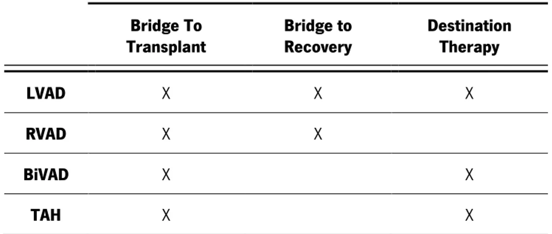
Furthermore, the selection and use of a mechanical circulatory support devices depends on the clinical scenario(Hoshi et al. 2005; Greatrex 2010):
1. Bridge to Transplant - Patients awaiting cardiac transplant can be implanted with a VAD to support the diseased heart until a donor organ is available.
2. Bridge to Recovery - Patients with reversible forms of cardiac disease can be implanted with a VAD, used in conjunction with regenerative medicine.
3. Destination Therapy - Patients with irreversible cardiac disease who are ineligible for transplant can be implanted with a VAD or TAH that is aimed at long-term out-of-hospital use.
Table 2.2 summarizes the relation between the implanted device used and the clinical scenario of the patient.
Table 2.2 - Application of mechanical circulatory support devices under different clinical scenarios.
Bridge To
Transplant Bridge to Recovery Destination Therapy
LVAD X X X
RVAD X X
BiVAD X X
TAH X X
2.4.1 Types of Cardiac Assist Devices
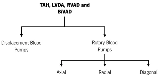
Mechanical cardiac assist devices (MCAD) are typically classified into two groups, according to their characteristic outflow: displacement blood pumps and rotary blood pumps. A summary of the different types of blood pumps is shown in Figure 2.5.
Figure 2.5 - Diagram of current solutions of cardiac assist devices; adapted from Reul & Akdis (2000).
2.4.1.1 Displacement Blood Pumps
Displacement blood pumps, the first generation of pumps, were initially developed with the aim of reproducing the pulsatile outflow delivered by the natural heart (Reul & Akdis 2000). As a result, the energy transfer in displacement pumps is characterized by periodic changes of a working space (Reul & Akdis 2000).
Normally, these type of pumps have an inherently large tissue and blood contacting surface. Furthermore, they have multiple moving mechanical parts, incorporating different valves, devices with flexible membranes, pneumatically or electrically actuated sacs and diaphragms or pusher plates (Timms 2011; Song et al. 2004).
Despite the simplicity of operation and the improved one-year survival observed in patients treated with these devices vs. optimal medical therapy, displacement blood pumps are often flawed with reliability and durability problems, by virtue of their mode of operation (Timms 2011; Reul & Akdis 2000).
The complexity and variety of displacement pumps components promote numerous mechanical failures due to wear, two or three years after the implantation in the patients. Moreover, the elevated contact with tissues and the formation of particle spallation (process in which fragments of material are ejected from a body due to impact), resulting from wear components, causes an inherent risk of infection, thrombus formation and blood trauma (Timms 2011). Additionally, the patients have very little mobility due to the bulky driving consoles (Reul & Akdis 2000).
TAH, LVDA, RVAD and BiVAD Displacement Blood Pumps Rotory Blood Pumps Axial Pumps Radial Pumps Diagonal Pumps
2.4.1.2 Rotary Blood Pumps
The numerous disadvantages presented by displacement blood pumps led to an effort to develop continuous flow devices based on a rotating impeller. As resulted, rotary blood pumps (RBPs) have become a common clinical therapy and an important alternative to displacement blood pumps, due to the improved outcomes for patients treated with these devices (Vollkron et al. 2004). RBPs are constituted by a rotating impeller housed within a small pump chamber (without need of directional valves). (Timms 2011; Park et al. 2005).
The original rotary blood pumps were the second generation of pumps, which are characterized by contact shaft/roller bearing or a blood immersed (pivot) bearing impeller support mechanism. Despite the good results of these pumps, the mechanical contact continues to pose a severe contraindication for long-term use (more than five years). Aiming to solve this problem, many solutions have been proposed, resulting in the third generation of blood pumps. These new pumps utilize contactless suspension mechanisms (magnetic or hydrodynamic forces) to eliminate mechanical contact and, consequently, wear (Timms 2011; Olsen 2000; Hoshi et al. 2006).
RBPs have distinct physiological and technological advantages in comparison with first generations blood pumps. In fact, they are smaller in size, which is an important characteristic both in terms of level of implantability as well in terms of level of transportability and integration into more complex devices. Furthermore, they require much less power, with a minimum of moving parts and no valves or flexing plastic chambers being needed. Therefore, this type of blood pumps results in lower blood damage, lower filling volume and absence of spallation. Furthermore, the lower pulsatility that results from the continuous transport mechanism, which was expected to be a disadvantage, has proven its suitability for patient recovery and rehabilitation (Reul & Akdis 2000; Vollkron et al. 2004).
Although RBPs present a series of advantages that are distinctive, they also present two primary disadvantages. One of them is the unknown shear stresses within the pumping chamber that could result in blood cell damage. It is important to refer that excessive blood cell injury caused by high shear stress could result in hemolysis. The second disadvantage is that continuous flow requires higher blood output volumes than pulsatile flow (Olsen 2000).
Depending on impeller geometry and the direction in which the blood enters and leaves the impeller, the rotary blood pumps can be classified into three main categories: axial, radial (centrifugal) and diagonal (mixed flow) pumps (Timms 2011).
Axial flow pumps
Axial flow pumps have a tubular configuration and they are smaller and lighter than radial pumps. Despite these advantages, and as result of their size, this type of pump normally uses second generation technology (even so, third generation pumps have also been utilized) (Fraser et al. 2011; Timms 2011).
Compared to other rotary type devices, axial pumps require much faster rotation speeds since they produce higher flows with lower pressure rises. In face of their higher velocity requirements, there is a relatively higher shear stress, which when combined with stationary guide vanes and contact impeller suspension may lead to hemolysis or thrombosis. (Timms 2011; Reul & Akdis 2000).
The excepted lifespan of axial pumps is around five years (however, there are cases in which they outlast this period). This limited lifespan is mainly due to the combination of high rotation speed and contact bearing mechanism (Timms 2011).
Currently, there are some axial flow devices that are commonly used clinically, such as: DeBakey, Jarvik 2000 and HeartMate II (Reul & Akdis 2000).
Radial /Centrifugal flow pumps
Radial pumps convert the axial flow, entering the inlet of the pump, into a radial flow, exiting the outlet. This type of pumps are the most capable of producing higher pressures at lower flow rates (Reul & Akdis 2000; Fraser et al. 2011).
Generally, radial pumps are used for long term cardiac assistance due to their lower corresponding rotation speed and higher hydraulic efficiency (Reul & Akdis 2000).
Furthermore, and despite being wider in diameter than axial pumps, these pumps are pancake-shaped (they are flatter), which is a more suitable shape for anatomical fitting. They are often used with third generation bearing technology. For this reason, the component of wear is completely eliminated, since the impeller is completely suspended using hydrodynamic or magnetic bearing forces (Timms 2011).
In general, radial pumps appear to have better results than other type of rotary blood pumps and, due to their particular characteristics, show a longer lifespan, of roughly ten years (Timms 2011).
Radial flow devices are commonly clinically accepted, with some examples of these devices being the HeartMate III, HeartWare and DuraHeart (Reul & Akdis 2000).
Diagonal (Mixed) flow pumps
This type of pumps is a combination of axial and radial flow pumps, and, for this reason, they tend to have the capability of generating high pressures and high flows. Normally, these diagonal pumps are associated with second generation techniques due to the difficulty of completely suspending the impeller (Reul & Akdis 2000; Timms 2011).
In clinical practice, some commonly used diagonal flow devices are: VentrAssist and HeartQuest (Reul & Akdis 2000).
Despite initial scepticism within the medical community, the number of patients ultimately supported with continuous flow type devices is increasing. For this reason cardiovascular device manufacturers are more and more interested in investing in the development of this type of devices (Timms 2011).
2.4.2 Hydrodynamic and Electromagnetic Bearings in Third Generation Blood Pumps
As previously mentioned, third generation blood pumps use hydrodynamic and electromagnetic bearing technology to suspend the impellers without contact. The most significant advantage of a levitated impeller is the improved life expectancy of the device.
Hydrodynamic Bearings
A hydrodynamic bearing uses a thin layer of fluid to separate two objects that are in relative motion to each other. As such, the use of hydrodynamic bearings to support the pump rotor is based on the formation of a thin fluid film of blood between the rotor and the stator. This blood fluid film supports the rotor loads, without any contact. The working principle is based on the hydrodynamic pressure generation in the fluid (Eling et al. 2013).
This type of support presents two main disadvantages: it requires particular operating conditions, such as a minimum and maximum rotation speed or pump flow conditions; and the bearing clearances may cause shear damage to red blood cells and lead to hemolysis (Greatrex 2010).
Magnetic Bearings
A magnetic bearing system supports a load using magnetic levitation. The interaction between magnetic fields generates a lifting force that suspends the rotor. Once again, this type of suspension avoids any type of physical contact. Compared to the hydrodynamic bearings, the magnetic bearings can be designed to operate with a larger clearance gap and can achieve a stable levitation at almost all operation conditions (Maslen & Schweitzer 2009).
The magnetic bearings can be divided in two groups: passive magnetic bearings (PMB) and active magnetic bearings (AMB).
PMB achieve contact-free levitation of an object through magnetic fields generated by static sources such as permanent magnets. PMB can be used to create an attractive or repulsive force. By placing same-pole magnets in juxtaposition, it is possible create a repulsive force. Conversely, by placing opposite pole magnets pairs near each other, an attractive force is generated. Depending on the configuration, stabilization in both the radial and axial directions are possible. However, it is not possible to stabilize all degrees of freedom of a body by passive magnetic levitation alone.The main advantage of these magnetic bearings is mechanical simplicity, since they do not use any active component (Greatrex 2010; Maslen & Schweitzer 2009).
AMB use electromagnetic actuators in order to control the position of the levitated object. In contrast to PMB, a stable levitation is possible using only AMBs, since any degree of freedom can be stabilized. However, AMBs are an unstable system, therefore they require an electronic control system. Though this control system introduces a degree of complexity in AMB systems, it allows to adjust and control the bearing performance in real-time (Maslen & Schweitzer 2009).