obtained for all other uses, in any current or future media, including reprinting/republishing this material for advertising or promotional purposes, creating new collective works, for resale or redistribution to servers or lists, or reuse of any copyrighted component of this work in other works.
L. M. R. Oliveira, A. J. M. Cardoso: "Power transformers behavior under the occurrence of inrush currents and turn‐to‐turn winding insulation faults", Proc. International Conference Electrical Machines, Rome (ICEM 2010), Italy, September 2010.
http://ieeexplore.ieee.org/xpls/abs_all.jsp?arnumber=5608303
Abstract -- This paper intends to provide a detailed charac-terization of the transformer behavior under the influence of inrush currents and/or incipient winding faults. Experimental and simulation results are presented and discussed. Finally, a promising new method to identify inrush currents, and to distinguish them from internal faults, is suggested.
Index Terms—Incipient winding faults, inrush currents, pro-tective relaying, transformers.
I. INTRODUCTION
OWER and distribution transformers have formed an essential part of electricity supply networks since the alternating current system was adopted more than a century ago [1]. In general, transformer breakdowns are relatively few, but repair and replacement of large transfor-mer units means considerable expenditure and time, and further, if faulted units are not cleared quickly and selec-tively can cause serious damage and power system stability problems. Protective schemes applied to transformers thus play a vital role in the economics and operation of a power system. The percentage cost of protection compared with the capital cost of the transformer being protected is extremely small making it totally uneconomic to apply anything less than a complete scheme of protection, to large transformer units [2].
The most difficult transformer winding fault for which to provide protection is the fault that initially involves only one turn [3]. A short-circuit between turns can start with point contact resulting from mechanical forces, from insulation deterioration due to excessive overload, a loose connection or breakdown of transformer insulation by an impulse vol-tage [4]. Initially, the insulation breakdown leads to internal arcing, which results in a low current, high impedance fault [5]. Usually, this incipient inter-turn insulation failure does not draw sufficient current from the line to operate an ordi-nary overload circuit-breaker or even more sensitive ba-lanced protective gear [6]. This turn-to-turn fault will then progress, with random propagation speed, involving addi-tional turns and layers, leading to a high current, low imped-ance fault, [7], [8]. Failure of the protection devices to detect these faults and quickly isolate the transformer may cause severe damage to the device and seriously affect the power
This work was supported in part by the Portuguese Foundation for Science and Technology (FCT) under Project Nº SFRH/PROTEC/49261 /2008 and Project Nº SFRH/BSAB/950/2009.
L. M. R. Oliveira is with the High Institute of Engineering, University of Algarve, P-8005-139 Faro, Portugal. He is also with the Instituto de Telecomunicações, P-3030-290 Coimbra, Portugal (e-mail: [email protected]).
A. J. M. Cardoso is with the Department of Electrical and Computer Engineering, Faculty of Sciences and Technology, University of Coimbra, P-3030-290 Coimbra, Portugal. He is also with the Instituto de Telecomunicações, P-3030-290 Coimbra, Portugal (e-mail: [email protected]).
system stability.
Differential protection relays has long been the accepted method for fault protection of power transformers [9]. The principle of this protection is based on a comparison of the primary and secondary currents. If these currents are dispro-portional, an internal fault is assumed and the transformer is switched off [10].
Differential relays are prone to misoperation in the pres-ence of transformer inrush currents, which result from tran-sients in transformer magnetic flux [11]. It is a well known fact that when a transformer is switched-on, the transient magnetizing current which flows may reach very high val-ues, and may persist for several seconds, depending upon the amount of residual magnetization left in the transformer core from former operation and upon the point of the voltage waveform at which the switch is closed [12]. Since this cur-rent flows into only one winding, it appears as a fault curcur-rent to the differential relay, and may cause the device to operate [4]. Proposed more than 70 years ago [12], the harmonic current restrained principle is commonly used to discrimi-nate between switching-on transients and internal faults. Typically, the second harmonic is a major component of the inrush current. In contrast, the fault harmonics are generally small. Thus, the second harmonic provides an effective means to distinguish between faults and inrush [13].
Although the second harmonic restraint principle is widely used in industrial application for many years, it often encounters some problems [14], such as:
1) low level of second harmonic in inrush current in mod-ern transformers, as compared to units of older designs [15]-[16];
2) the second harmonic restrain may sometimes increase fault clearance time for heavy faults, followed by current transformer saturation [16];
3) if a fault exists at the time the transformer is energized, harmonics in the magnetizing inrush current may prevent it from operating [4], [17];
4) in the case of delta connected current transformers the relay currents are obtained by subtracting the line currents. It is possible that, due to the subtraction effect, the currents seen by the relay have a reduced amount of 2nd harmonic
component, which is likely to cause a security concern in differential protection during transformer energization [18], [19].
Additionally, in the case of turn-to-turn insulation faults, even though the currents at the fault location may possibly be very high and dangerous, the differential currents are rel-atively small [17]. The traditional transformer differential protection is typically not sensitive enough to detect such winding defects before they developed into more serious and costly to repair ground-faults [20].
As it is evident from the preceding paragraphs, it is of
Power Transformers Behavior Under
the Occurrence of Inrush Currents and
Turn-To-Turn Winding Insulation Faults
Luís M. R. Oliveira, A. J. Marques Cardoso
prime importance the development of protection schemes, which can improve the sensitivity of differential relays to detect incipient turn-to-turn winding faults and which can also provide a solution to the second harmonic restrain drawbacks. Obviously, prior to the development of these protection systems, a detailed characterization of the power transformer behavior under the occurrence of turn-to-turn winding faults and inrush currents is required.
The purpose of this paper is twofold: (i) to present a de-tailed characterization of the transformer behavior under the influence of inrush currents and/or incipient winding faults and (ii) to suggest a promising new method to detect low--level turn-to-turn faults and, also, to distinguish them from magnetizing inrush current transients.
II. EXPERIMENTAL SETUP AND TRANSFORMER MODEL
For the experimental investigation a three-phase, two winding, three leg transformer, of 10.3 kVA, 230/132 V, was used. The primary and the secondary windings have 152 and 90 turns, respectively. In each winding of the transfor-mer there are five additional tappings connected to the coils, allowing for the introduction of shorted turns at several lo-cations in the winding, as shown in Fig. 1, for the phase R of the transformer low voltage winding.
For the experimental analysis of the switching-on tran-sients, the point of the voltage wave at which the transfor-mer is energized is controlled by using electronic switches in a custom built power electronics board. Before each switching the transformer core is demagnetized: first an in-creasing ac voltage supply is applied to the primary wind-ings until the core reaches saturation; this ac voltage is then slowly reduced to zero to eliminate the residual flux in the core.
The faults are introduced in the test transformer by con-necting a shorting resistor at the terminals of the affected turns. The value of this resistor (Rsh) was chosen so as to
create an effect strong enough to be easily visualized, but simultaneously big enough to limit the short-circuit current and thus protect the test transformer from complete failure when the short is introduced. The instant at which the fault occurs is adjusted by another power electronics board, simi-lar to the one used to study the transformer energization transients.
If the fault occurs in the primary winding, the short--circuited turns act as an autotransformer load on the winding, as shown in Fig. 2(a), where Rsh represents the
fault impedance. However, if the fault takes place on the secondary winding, the short-circuited turns act as an ordi-nary double winding load, Fig. 2(b), [6].
The experimental study of winding inter-turn short--circuits occurrence presents some inherent difficulties: the current in the shorted turns must be limited to the rated cur-rent of the winding and the fault location is fixed by the tap-pings position. Therefore, a detailed analysis of these phe-nomena can be better investigated by the additional use of a suitable digital simulation transformer model. For that pur-pose, a coupled electromagnetic transformer model was de-veloped [21], which is based on the combination of both magnetic and electric lumped parameters equivalent circuits, allowing for the modeling and simulation of the transformer in its natural electromagnetic environment. A detailed
de-scription of the model implementation and validation can be found in [21].
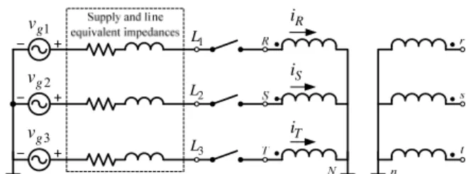
The results presented in this paper refer to an YNyn0 transformer winding connection and no-load conditions. The transformer was energized by the low-voltage side and the supply and line equivalent impedances were taken into ac-count in the simulation study (Fig. 3).
The instrumentation system basically comprises a per-sonal computer, a data acquisition board and clip-on current probes.
III. CHARACTERIZATION OF TRANSFORMER TRANSIENTS
This section presents and discusses experimental and si-mulation results for the following cases: inrush currents, turn-to-turn winding faults, and the simultaneous occurrence of these conditions. Particular attention is given to the har-monic content of the winding currents.
A. Case I: Transformer Energization
The transformer terminals were connected simultaneously to the supply when the voltage between line 1 (L1) and the
neutral (N) is starting its positive half-cycle, as can be seen in the waveforms of Fig. 4 (notation as per Fig. 3). Transfor-mer energization occurs at t = 20 ms.
Typical inrush current waveforms were obtained. Fig. 4 presents the experimental winding currents and the primary--side voltage of phase R. Fig. 5 presents the corresponding simulated results, which are in good agreement with the ex-perimental ones.
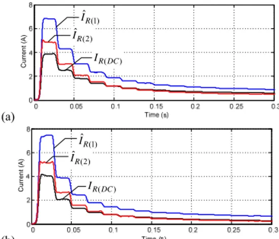
The harmonic content of the transient inrush currents was calculated using a Discrete Fourier Transform with a moving window. Fig. 6 presents the evolution of the DC, the funda-mental and the second harmonic components of the phase R current during the energization of the transformer.
The evolution of the ratio of the second harmonic to the
Fig. 1. Location of the tappings for transformer low-voltage winding (phase
R). (a) RN v Np R i rn v Ns r i b i x i Rsh (b) RN v Np R i rn v Ns r i b i x i Rsh
Fig. 2. Equivalent circuits for a fault occurring in the: (a) primary winding; (b) secondary winding, (phase R).
R i S i T i 1 g v 3 g v 2 g v 1 L 2 L 3 L
-200 0 200 V o lt ag e ( V ) RN v 0 10 20 Cu rre nt (A) iR -8 -6 -4 -2 0 2 C u rre nt (A ) S i 0 0.05 0.1 0.15 0.2 0.25 0.3 -8 -6 -4 -2 0 2 Cu rre nt (A) Time (s) T i
Fig. 4. Experimental results: primary-side voltage of phase R waveform and winding current waveforms.
RN v R i S i T i
Fig. 5. Simulated results: primary-side voltage of phase R waveform and winding current waveforms.
(a) C u rr en t (A ) (1) ˆ R I ( ) R DC I (2) ˆR I (b) C u rr en t (A ) (1) ˆ R I ( ) R DC I (2) ˆ R I
Fig. 6. DC, fundamental and second harmonic components of the phase R current during the energization of the transformer. (a) Experimental results. (b) Simulated results. pe rc en ta ge (% ) 21 I I
Fig. 7. Ratio of the second harmonic to the fundamental of the inrush cur-rents (simulated results).
fundamental of the inrush currents (I2/I1) is presented in
Fig. 7. The operation of the differential relay is usually blocked if this ratio is larger than 15%-20% [16], [17]. As-suming a restraint ratio of 20%, it can be seen from Fig. 7 that the transformer protection is inhibited during 0.6 s for phase R and more than 0.3 s for the other phases.
B. Case II: Turn-to-Turn Winding Fault Transient
The severity of the fault depends not only on the number of shorted turns, but also on the value of the fault current, which is limited by the fault impedance. The fault is intro-duced in the primary winding of phase R, and the turns are shorted, through the auxiliary resistor, when the voltage across the taps uB-uD (Fig. 1) begins the positive half-cycle.
1) Incipient fault without overcurrent
The auxiliary resistor was adjusted to 0.2 Ω, so that the current in the shorted turns is limited to the rated value of the current in the affected winding (Ib=Irated).
Both experimental and simulated primary-side current waveforms are shown in Fig 8(a) and 8(b), respectively, which are in relatively good agreement. The fault is intro-duced at t = 60 ms. The occurrence of primary-side interturn short-circuits leads to an increment in the magnitude of the current in the affected winding, as compared to a healthy condition. It can be seen from these results that the current in the damaged winding increases almost instantaneously when the fault is introduced, maintaining a nearly symmetrical and sinusoidal waveform.
The current waveform in the shorted turns, ib, and the
current waveform in the fault impedance, ix, are shown in
Fig. 9 (notation as per Fig. 2). The current ix is reflected to
the primary side through the turns ratio between the number of shorted turns, Nb, and the total number of turns of the
primary-side winding, Np. As a result, the increase in the
magnitude of the primary-side winding current, due to an in-cipient insulation defect, with only a few turns involved, is small, even if the fault current is large. This in particular ap-plies to the present case, where none of the rated parameters of the test transformer are exceed, and it is very likely that the fault remains undetected by the protection devices, until it progresses to a major failure.
2) Incipient fault with overcurrent
The analysis of the transformer behavior under the occur-rence of more severe turn-to-turn faults cannot be carried out experimentally, due to the physical limitations of the test transformer. Using the digital simulation model a more se-vere fault was analyzed, with the same number of shorted turns as before, but with a fault current of approximately 2.5 times the rated current of the primary winding.
Fig. 10 presents the evolution of the DC, fundamental and second harmonic components of the phase R current during the fault occurrence. After the fast current rise, the DC and the second harmonic components are negligible, and only the fundamental component is affected by the occurrence of the fault. For the case of the moderate fault (Ib=2.5Irated),
the fundamental component increases about 10 times when the fault occurs (Fig. 10) and this differential signal reaches up to 12% of the transformer winding rated current. This could be sufficient to trip the differential relay, depending on the minimum pick-up current required for the operation of the protection device.
For the case of the incipient fault without overcurrent (Ib=Irated), both experimental and simulated results are also
presented in Fig. 10, which are in relatively good agreement.
(a) R i S i T i (b) R i S i T i
Fig. 8. Winding current waveforms for the case of four shorted turns in the primary winding (phase R; Rsh 0.2 Ω): (a) experimental; (b) simulated.
(a) x i b i R i (b) x i b i R i
Fig. 9. Fault related current waveforms for the case of four shorted turns in the primary winding (phase R; Rsh 0.2 Ω): (a) experimental; (b) simulated.
(a) 0 0.02 0.04 0.06 0.08 0.1 0.12 0.14 0.16 0.18 0.2 0 1 2 3 4 5 Time (s) Healthy Faulty ( ) R DC I (2) ˆ R I (1) ˆ R I (b) C u rre n t (A ) (1) ˆ R I (2) ˆ R I ( ) R DC I
Fig. 10. DC, fundamental and second harmonic components of the phase R current during a turn-to-turn winding fault transient. (a) Experimental re-sults. (b) Simulated results; solid line: Ib = Irated; dashed line: Ib =2.5 Irated.
C. Case III: Simultaneous Inrush and Winding Fault The most challenging situation for the differential pro-tection function is the case where a turn-to-turn fault exists in the winding before the transformer is switched on [22]. The insulation failures in transformers have been known to occur at the instant of energizing, particularly in the case of transformers that have been standing idle for long periods of time [23]. In fact, the fault may be caused by the vibration of the windings caused by the inrush current itself [17], [24]. Fig. 11 shows the current waveform in the phase R when the transformer is energized, with the same conditions of Case I, but with four shorted turns in phase R, with Ib=2.5Irated and
Rsh=0.02 Ω. It can be seen that the current waveform is
dominated by the inrush transient during the first cycles after the energization. Comparing with the inrush current obtained under healthy conditions (Fig. 5), it can be concluded that the fault current component is responsible for a small in-crease in the positive peaks of iR and for the presence of
negative half-cycles, after the switching-on of the transfor-mer.
Similar conclusions can be drawn from comparisons of the harmonic content of iR, under healthy (Fig. 6) and faulty
conditions (Fig. 12): the presence of the fault leads to an in-crement in the fundamental component, whereas the DC and second harmonic components are identical to the ones ob-tained under no fault conditions.
The per-phase second harmonic ratios for all the three phases are illustrated in Fig. 13. As a consequence of the fault, this ratio decays faster in the damaged phase, as com-pared to a healthy condition. Even so, the operation of the relay is delayed: if a per-phase blocking scheme is used the protection in the affected phase is blocked during 70 ms,
R
i
Fig. 11. Phase R winding current waveform for the case of transformer energization with four shorted turns in the phase R of the primary winding (simulated results; Ib =2.5 Irated).
C u rr ent (A ) (1) ˆ R I ( ) R DC I (2) ˆ R I
Fig. 12. DC, fundamental and second harmonic components of the phase R current for the case of transformer energization with four shorted turns in the phase R of the primary winding (simulated results; Ib =2.5 Irated).
0.7 0 0.1 0.2 0.3 0.4 0.5 0.6 0 20 40 60 80 Time (s) Phase R Phase S Phase T pe rc en ta ge (% ) 21 II
Fig. 13. Ratio of the second harmonic to the fundamental of the winding currents for the case of transformer energization with four shorted turns in the phase R of the primary winding (simulated results; Ib =2.5 Irated).
approximately. However, if a three-phase cross-blocking method is employed, the tripping signal is inhibited during the same time as in the healthy inrush (0.3 s), and the trans-former protection is uncertain.
IV. EPVABASED PROTECTION STRATEGY
Firstly applied to diagnose AC motors faults [25], the so- -called Extended Park's Vector Approach (EPVA) has been also proposed to identify turn-to-turn winding insulation de-fects in operating three-phase transformers [26]. This section presents preliminary results concerning the application of the EPVA as a protection method.
A. EPVA Computation
As a function of the three-phase differential variables (iRd,
iSd, iTd), the transformer differential current Park's Vector
components (iD, iQ) are:
2 3
1 6 1 6 D Rd Sd Td i i i i (1)
1 2 1 2 Q Sd Td i i i (2)The Extended Park's Vector Approach (EPVA) is based on the spectral analysis of the AC level of the differential current Park's Vector modulus:
2 2
EPVA D Q D Q
i i j i i i (3)
Ideally, under healthy conditions, the EPVA signature will be clear from any spectral component, i.e., only a DC value is present in the current Park's Vector modulus.
The presence of a winding fault leads to an increment in the magnitude of the differential current in the affected phase, as compared to a healthy situation. Under these con-ditions the differential current Park's Vector modulus will contain a dominant DC level and an AC level, at twice the supply frequency (2f), whose existence is directly related to the asymmetries in the transformer. The amplitude of this spectral component is directly related to the extension of the fault and can be used as a signal for the relay operation.
An indicator of the degree of asymmetry can also be de-fined as the ratio between the amplitude of the spectral com-ponent at the frequency of 2f and the DC level of the diffe-rential current Park's Vector [25]. The proposed fault sever-ity factor (SF) is thus expressed by:
(2 ) ( )
ˆ
EPVA f EPVA DC
SFI I (4)
Further details of the theoretical principles related with the EPVA can be found in [25].
B. EPVA Turn-To-Turn Fault Detection
Fig. 14 presents the relevant harmonic content of the EPVA, for the case of a fault occurrence in the winding of phase R (with the same conditions of section III-B-2). There is an increase in the DC and the 100 Hz (2f) components of iEPVA, as a consequence of the fault occurrence. After the
short transient at the time of the fault introduction, the 50 Hz component is negligible.
As stated before, the magnitude of the 2f spectral compo-nent is a reliable indicator of the presence of a fault, and can be used as a trip signal of the differential relay. In fact, the 100 Hz harmonic component increases about 15 times as a
result of the fault occurrence, giving an improved sensitivity to detect winding shorted turns, as compared to the funda-mental component of the current in the affected phase (which increases 10 times for the same type of fault, as seen before).
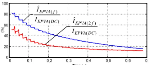
The evolution of the ratios ÎEPVA(2f)/IEPVA(DC) and
ÎEPVA(f)/IEPVA(DC) is presented in Fig. 15. As expected, the first
one gives information about the severity of the fault, and can also be included in the relay functionality for the online continuous monitoring of the transformer condition. The ra-tio ÎEPVA(f)/IEPVA(DC) is negligible before and after the current
rise in the affected winding, and doesn't provide any indica-tion about interturn short-circuits that may occur. However, it plays a very important role for discriminating between in-rush and fault conditions, as explained in the next section. C. EPVA Characteristics During Inrush Current
The harmonic content of the differential current Park's Vector modulus can be used to distinguish between trans-former energization and winding faults. As can be seen in Fig. 16, the 50 Hz component of the EPVA is largely af-fected by the magnetizing inrush transient. The reason for that is the asymmetrical waveform of the inrush currents. The transformer energization can be detected by using the ratio between the 50 Hz component and the DC value, as seen in Fig. 17, blocking the relay operation if this ratio is above a predefined threshold value.
( ) EPVA DC I (2 ) ˆ EPVA f I ( ) ˆ EPVA f I
Fig. 14. DC, 50 Hz, and 100 Hz harmonic components of the EPVA during a turn-to-turn winding fault transient (simulated results).
( ) ( ) ˆ EPVA f EPVA DC I I (2 ) ( ) ˆ EPVA f EPVA DC I I
Fig. 15. Ratios of the 50 Hz and 100 Hz harmonic components to the DC value of the EPVA during a winding fault transient (simulated results).
( ) ˆ EPVA f I ( ) EPVA DC I (2 ) ˆ EPVA f I
Fig. 16. DC, 50 Hz, and 100 Hz harmonic components of the EPVA during a transformer inrush transient (simulated results).
( ) ( ) ˆ EPVA f EPVA DC I I (2 ) ( ) ˆ EPVA f EPVA DC I I
Fig. 17. Ratios of the 50 Hz and 100 Hz harmonic components to the DC value of the EPVA during a transformer inrush transient (simulated results).
For the blocking signal generation it is sufficient that only one of the three differential currents possesses an asymme-tric waveform, since the EPVA strategy assemble the three--phase system in only one quantity. This eliminates the problem of the traditional per-phase second harmonic re-strain method, where a low value of a 2nd harmonic in one of the phases could lead to a false tripping of the relay. In this way, the EPVA strategy is a truly three-phase blocking scheme.
D. Simultaneous occurrence of fault and switching-on conditions: EPVA results
It is possible to detect low-level internal faults during the energization of the transformer by using the EPVA protec-tion strategy. However, a delayed operaprotec-tion of the relay is to be expected, since the high value of the asymmetric inrush currents affects the values of the 50 Hz and 100 Hz EPVA components.
The evolution of the severity factor is presented in Fig. 18, for the same conditions of the previous Case III. It can be seen that the inrush effect in the SF is dominant in the first three cycles following the transformer energization. After that the presence of the fault prevails and the SF grows to the steady-state value.
As compared to a healthy inrush condition, the blocking EPVA signal (ÎEPVA(f)/IEPVA(DC)) decays faster, Fig. 18. This
result is similar to the one obtained by the traditional per--phase ratio I2/I1, presented in Fig. 13, and the relay is
blocked during a time that depends on the restrain prede-fined threshold value.
V. CONCLUSIONS
This paper presents a detailed characterization of the transformer behavior under the influence of inrush currents and/or incipient winding faults. Experimental and simulation results were presented and discussed.
A novel approach for the differential protection of a power transformer is suggested. Initial results indicate that, in general, the proposed EPVA based strategy provides reli-able protection, enhanced sensitivity for internal faults and a truly three-phase detection factor for blocking trips on in-rush transients.
Further work is currently in progress, concerning the re-finement of the proposed protection technique, with the aim of dealing with transient overvoltages, current transformers saturation, sympathetic and recovery inrush currents, or even, the surrounding presence of power electronics equip-ment.
VI. REFERENCES
[1] C. Ashmore, "Transforming technology," International Power
Generation, vol. 22, pp. 25-26, March 1999.
[2] D. Robertson, Power System Protection Reference Manual: Reyrolle
Protection, London: Oriel Press Ltd., 1982.
[3] IEEE guide for protective relay applications to power transformers, IEEE Standard C37.91-2000, March 2000.
[4] E. A. Klingshirn, H. R. Moore, and E. C. Wentz, "Detection of faults in power transformers," AIEE Trans., vol. 76, pp. 87–95, Apr. 1957. [5] P. Barkan, B. L. Damsky, L. F. Ettlinger, and E. J. Kotski,
"Overpres-sure phenomena in distribution transformers with low impedance faults: experiment and theory," IEEE Trans. Power Apparatus and
Systems, vol. 95, pp. 37-48, Jan./Feb. 1976.
0.7 0 0.1 0.2 0.3 0.4 0.5 0.6 0 20 40 60 80 100 (% ) Time (s) ( ) ( ) ˆ EPVA f EPVA DC I I (2 ) ( ) ˆ EPVA f EPVA DC I I
Fig. 18. Ratios of the 50 Hz and 100 Hz harmonic components to the DC value of the EPVA for the case of transformer inrush with four shorted turns in the phase R of the primary winding (simulated results; Ib =2.5 Irated).
[6] S. A. Stigant and A. C. Franklin, The J&P Transformer Book, 10th ed., London: Newnes-Butterworths, 1973.
[7] C. W. Plummer, G. L. Goedde, E. L. Petit, J. S. Godbee, and M. G. Hennessey, "Reduction in distribution transformer failures rates and nuisance outages using improved lightning protection concepts," IEEE
Trans. Power Delivery, vol. 10, pp. 768-777, Apr. 1995.
[8] J. M. Lunsford and T. J. Tobin, "Detection of and protection for inter-nal low-current winding faults in overhead distribution transformers,"
IEEE Trans. Power Delivery, vol. 12, pp. 1241-1249, July 1997.
[9] C. D. Hayward, "Harmonic Current-Restrained Relays for Transfor-mer Differential Protection," AIEE Trans., vol. 60, pp. 377-382, 1941. [10] X. Guo, H. A. Maier, and K. Feser, "A new inrush detection method
for transformer differential protection," Electrical Engineering (Archiv
fur Elektrotechnik), vol. 76, pp. 83-91, Jan. 1992.
[11] A. Guzmán, S. Zocholl, G. Benmouyal, and H. J. Altuve, "A Current-Based Solution for Transformer Differential Protection – Part I: Prob-lem Statement," IEEE Trans. Power Delivery, vol. 16, pp. 485-491, Oct. 2001.
[12] L. F. Kennedy and C. D. Hayward, "Harmonic-current-restrained re-lays for differential protection," AIEE Trans., vol. 57, pp. 262–266, 1938.
[13] M. Thompson and J. R. Closson, "Using IOP characteristics to
trouble-shoot transformer differential relay misoperation," in Proc.
Interna-tional Electrical Testing Association Technical Conference, 2001.
[14] H. Zhang, P. Liu, and O. P. Malik, "A new scheme for inrush identification in transformer protection," Electric Power Systems
Re-search, vol. 63, pp. 81-86, Sept. 2002.
[15] B. Kasztenny and A. Kulidjian, "An improved transformer inrush re-straint algorithm increases security while maintaining fault response performance," in Proc. 53rd Annual Conf. Protective Relay Engineers, 2000.
[16] F. Mekic, R. Girgis, Z. Gajic, and E. teNyenhuis, "Power transformer characteristics and their effect on protective relays," in Proc. 33rd
Western Protective Relay Conference, 2006.
[17] A. Wiszniewski, W. Rebizanta, and L. Schiel, "New algorithms for power transformer inter-turn fault protection," Electric Power Systems
Research, vol. 79, pp. 1454-1461, Oct. 2009.
[18] R. Patterson, W. McCannon, and G. Kobet, "A consideration of inrush restraint methods in transformer differential relays," in Proc. 54th
An-nual Georgia Tech Protective Relaying Conference, 2000.
[19] S. E. Zocholl, "Transformer protection - an analysis of field cases," in
Proc. 25th Annual Western Protective Relay Conference, 1998.
[20] Z. Gajic, I. Brncic, B. Hillström, F. Mekic, and I. Ivankovic, "Sensitive turn-to-turn fault protection for power transformers," Proc. 32th
An-nual Western Protective Relay Conference, 2005.
[21] L. M. R. Oliveira and A. J. M. Cardoso, "A permeance-based transfor-mer model and its application to winding interturn arcing fault stu-dies," Accepted for publication in IEEE Trans. Power Delivery. [22] M. Kezunovic and Y. Guo, "Modeling and simulation of the power
transformer faults and related protective relay behavior," IEEE Trans.
Power Delivery, vol. 15, pp. 44-50, Jan. 2000.
[23] L. F. Blume, G. Camilli, S. B. Farnham, and H. A. Peterson, "Transformer magnetizing inrush currents and influence on system op-eration," AIEE Trans., vol. 63, pp. 366−375, Jan. 1944.
[24] M. Steurer and K. Fröhlich, "The impact of inrush currents on the me-chanical stress of high voltage power transformer coils," IEEE Trans.
Power Delivery, vol. 17, pp. 155-160, Jan. 2002.
[25] S. M. A. Cruz and A. J. M. Cardoso, "Stator winding fault diagnosis in three-phase synchronous and asynchronous motors, by the Extended Park's Vector Approach," IEEE Trans. Industry Applications, vol. 37, pp. 1227-1233, Sept./Oct. 2001.
[26] L. M. R. Oliveira and A. J. M. Cardoso, "Incipient turn-to-turn winding fault diagnosis of power transformers by the on-load exciting current Extended Park's Vector Approach," Proc. Advanced Research
Luís M. R. Oliveira was born in Coimbra, Portugal in 1970. He received
the Electrical Engineering Diploma and the M.Sc. degree from the Univer-sity of Coimbra, Coimbra, Portugal, in 1995 and 2001, respectively, where he is currently pursuing the Dr. Eng. Degree in electrical engineering. In 1996 he joined the High School of Technology of University of Algarve, Portugal, where he is currently an Adjunct Professor.
A. J. Marques Cardoso (S’89–A’95–SM’99) was born in Coimbra,
Por-tugal, in 1962. He received the E.E. diploma and the Dr.Eng. degree from the University of Coimbra, Coimbra, Portugal, in 1985 and 1995, respec-tively. Since 1985, he has been with the University of Coimbra, where he is currently an Associate Professor in the Department of Electrical and Com-puter Engineering and Director of the Electrical Machines Laboratory. His teaching interests cover electrical rotating machines, transformers, and maintenance of electromechatronic systems, and his research interests are focused on condition monitoring and diagnostics of electrical machines and drives. He is the author of a book entitled Fault Diagnosis in Three-Phase
Induction Motors (Coimbra, Portugal: Coimbra Editora, 1991), (in
Portu-guese) and more than 200 papers published in technical journals and confe-rence proceedings. Dr. Marques Cardoso is actively involved in the field of standardization on condition monitoring and diagnostics, both at the na-tional and internana-tional level, where he has been acting as a convenor of ISO/TC 108/SC 5 Advisory Group C (Condition Monitoring of Electrical
Motors and Generators, for the Purposes of Diagnostics), Advisory Group D (Condition Monitoring and Diagnostics of Power Transformers) and Work-ing Group 10 (Condition MonitorWork-ing and Diagnostics of Electrical Equip-ment), and a member of the IEEE Standards Association, and of several working groups and balloting committees of ISO, IEC, and CEN. He is cur-rently an Associate Editor of the International Journal of Systems
Assur-ance Engineering and Management (Springer), a member of the Editorial
Board of the International Journal of Condition Monitoring & Diagnostic
Engineering Management (COMADEM International, U.K.), an Honorary
Member of the International Biographical Centre Advisory Council, Cam-bridge, U.K., and an Honorary Professor of the Albert Schwitzer Interna-tional University, Geneva, Switzerland. He is a member of the New York Academy of Sciences, the European Power Electronics and Drives Associa-tion (EPE), the InternaAssocia-tional AssociaAssocia-tion of Science and Technology for Development, the Electrical Machines and the Industrial Drives Committees of the IEEE Industry Applications Society, the Electrical Machines and the Power Electronics Committees of the IEEE Industrial Electronics Society, the Technical Committee on Diagnostics of the IEEE Power Electronics So-ciety, the Portuguese Federation of Industrial Maintenance (APMI), and a senior member and Specialist Engineer in Industrial Maintenance of the Portuguese Engineers Association (ODE). He has been listed in Who’s Who
in the World, Who’s Who in Science and Engineering, Who’s Who in Finance and Industry, International Who’s Who of Professionals, and BEST