DOI 10.1007/s10514-016-9609-6
A cable-driven robot for architectural constructions:
a visual-guided approach for motion control and path-planning
Andry Maykol Pinto1 · Eduardo Moreira2 · José Lima3 · José Pedro Sousa4 · Pedro Costa1
Received: 20 October 2015 / Accepted: 12 October 2016 / Published online: 27 October 2016 © Springer Science+Business Media New York 2016
Abstract Cable-driven robots have received some attention by the scientific community and, recently, by the industry because they can transport hazardous materials with a high level of safeness which is often required by construction sites. In this context, this research presents an extension of a cable-driven robot called SPIDERobot, that was developed for automated construction of architectural projects. The pro-posed robot is formed by a rotating claw and a set of four cables, enabling four degrees of freedom. In addition, this paper proposes a new Vision-Guided Path-Planning System (V-GPP) that provides a visual interpretation of the scene: the position of the robot, the target and obstacles location; and optimizes the trajectory of the robot. Moreover, it determines a collision-free trajectory in 3D that takes into account the obstacles and the interaction of the cables with the scene. A set of experiments make possible to validate the contribution of V-GPP to the SPIDERobot while operating in realistic
B
Andry Maykol Pinto [email protected] Eduardo Moreira [email protected] José Lima[email protected] José Pedro Sousa [email protected] Pedro Costa [email protected]
1 INESC TEC and the Faculty of Engineering, University of
Porto, Porto, Portugal
2 INESC TEC, Porto, Portugal
3 INESC TEC and Polytechnic Institute of Bragança, Porto,
Portugal
4 Faculty of Architecture, University of Porto, Porto, Portugal
working conditions, as well as, to evaluate the interaction between the V-GPP and the motion controlling system. The results demonstrated that the proposed robot is able to con-struct architectural con-structures and to avoid collisions with obstacles in their working environment. The V-GPP system localizes the robot with a precision of 0.006 m, detects the
tar-gets and successfully generates a path that takes into account the displacement of cables. Therefore, the results demon-strate that the SPIDERobot can be scaled up to real working conditions.
Keywords Cable-driven robot·Vision-guided positioning·
Path-planning·Scene interpretation
1 Introduction
Over the past few decades, several technological advances in the robotics field, such as, robotic manipulators, autonomous guided-vehicles and sophisticated machinery, have pushed the automation level of the manufacturing industry fur-ther ahead by increasing the efficiency and flexibility of the production processes through a substantial reduction of their operating costs and manufacturing waste. Although the strong impact in this type of industries, the robotic technolo-gies were not accepted with the same level of success in other fields like the civil engineering (Hastak 1998;Vh et al. 2013). The reason for a slower automation rate may be related to the intrinsic characteristics of a conventional construction site: hard and hazardous environment. Therefore, the robotic systems must be designed by taking into consideration fea-tures that are relevant for heavy duties: endurance, flexibility, maintenance and reliability.
relatively simple to operate, inexpensive, ease to assemble and disassemble (multiple cables attached to a mobile plat-form). Noteworthy, they provide large workspaces, high pay-loads and reliable stiffness in lateral directions under external disturbances (Oh and Agrawal 2006), factors that make the cable-driven robots a strong possibility for constructing some civil structures. Besides these advantages, there are issues that must be considered before implementing a real and fully-sized solution, namely: the workspace is reduced because of the inability of cables to push (non-negative tension), inter-ferences among the cables and collisions with nearby objects. These problems led to some approaches (Oh and Agrawal 2006;Gouttefarde et al. 2011;German et al. 2001) that usu-ally define the controllable workspace of cable-driven robots using a force-feasible methodology. The kinematics model is obtained by the distribution of cable forces (Borgstrom et al. 2009): fully-constrained and under-constrained. The fully-constrained completely determines the position and ori-entation of the robot as a function of the cables length. This means, when considering a mobile robot with n degrees of freedom (DOF), the model is fully-constrained if the number of cables exceeds the number of DOFs. For under-constrained robots, its position and orientation cannot be completely determined by the cable’s length (depends on external forces such as the gravity force). Obviously, the position and orientation of cable-driven robots are obtained by actuating each cable however, force-feasible solutions restrict the workspace because they require a positive tension in all cables (Lahouar et al. 2009). This represents a straight disadvantage and is an inconvenience for realistic imple-mentations. The large majority of cable-driven robots use force-feasible systems for controlling the positioning which usually require more than four cables for augmenting the controllability (more DOFs are available) of the movement. However, a high number of cables reduce the working area and create additional problems to possible collisions with nearby obstacles.
This paper discusses a visual-based approach for these topics: the positioning of an under-constrained robot and, the estimation of the collision-free trajectory (considering the displacement of cables) in the working area. This visual-based approach is contextualized by a cable-driven robotic prototype named SPIDERobot (Moreira et al. 2015), whose main goal is to autonomously construct architectural projects. A brief description of this robot is provided in this research which includes an overview of the system architecture, the motion controlling system, physical limitations, the scene analysis, the localization of the robot and the path-planning mechanism that takes into account the presence of obstacles.
Therefore, the contributions of this research include:
– A novel system architecture for the SPIDERobot that includes a scheduling module (it manages the
construc-tion of the architectural project) and a visual module for interpreting the scenario;
– A Vision-Guided Path-Planning System (V-GPP) opti-mizes and creates the trajectory of the robot by avoiding all obstacles in the scene. The trajectory is calculated by a 3D path-planning technique based on A-star principle which resorts to a real-time visual analysis of the envi-ronment.
– A study of the interaction between the V-GPP and the Dynamic Controlling System (DCS) that controls the positioning of the robot. The visual information of the V-GPP and the kinematics model (of the DCS) are com-bined using a Kalman filter, which makes the movements of the robot more smooth along the navigation path; – Qualitative and quantitative evaluations in several
realis-tic scenarios (with obstacles);
– A new representation for architectural design and mod-eling of 3D sketches or constructions.
The paper is organized as follows: related works about cable-driven robots are discussed in Sects.2and3describes the robot. In detail, Sects.3.1,3.2and3.3present the system architecture, the DCS (brief introduction) and the V-GPP, respectively. The experiments and the respective discussions are presented in Sect.4. The results prove the ability of the visual-based positioning and trajectory planning for cable-driven robots since the proposed system revealed a small overall error and a reliable ability to avoid obstacles during the several realistic trials that were conducted as part of this work. Finally, the major conclusions are discussed in Sect.5.
2 Related works
Cable-driven robots, also known as array or cable-suspended robots, control an end-effector using multiple actuated cables (Usher et al. 2005). Cables are controlled usually by a positioning system (Borgstrom et al. 2008) that actuates in motors for rolling and unrolling cables. These robots are capable of performing many manipulation tasks and they have several conveniences over typical robotic manipulators (German et al. 2001): a smaller number of moving parts, a lower level of visual intrusion (Gouttefarde et al. 2011), a larger working area and a higher payload ratio relative to the robot’s weight. On the other hand, cable inter-ferences, inaccuracies at the end-effector due to cable stretch, and the limited force in the downward directions are some the disadvantages of cable-driven robot (Usher et al. 2005). Currently, there is a small number of cable-driven robotic systems available on the market of sports and entertain-ment (Borgstrom et al. 2008), namely, the SkyCam1and the
Cablecam.2However, a larger number of researching works can be found in the literature (Bosscher et al. 2007;Oh and Agrawal 2006;Lahouar et al. 2009) related to cable-driven robots. Although these works resort to a considerable diver-sity of robots with different geometries, number of cables and application fields, the large majority of them use tensor-feasible controlling systems for positioning the mobile robot in the workspace. In detail, the robot presented inBosscher et al.(2007) was designed for contour crafting. This robot has 12 cables that made possible to control the position of the end-effector. From this amount of cables, four upper-cables are used to support the weight of the mobile platform and the remaining 8 bottom-cables (grouped in pairs) are used by the positioning system to control the robot. The major disadvantages of this type of robots is that bottom-cables cause a severe reduction of the workspace and there is a higher probability of collisions between the cables and nearby objects. Authors try to solve this problem by intro-ducing horizontal crossbars in the frame where the robot is installed. These crossbars are actuated vertically which ele-vates the position of the bottom-cables and increasing the workspace. Although a very stable and clever solution, this approach requires a lot of hardware due to the amount of cables and the elevation of the bottom-cables. A cable-driven robot with the moving platform having a triangle shape is pre-sented inOh and Agrawal(2006). This platform is supported by six upper-cables, where a couple of cables is installed in each vertex. The research studied the dynamic aspects of the reachable domain in terms of achievable positions by pre-senting a Lyapunov-based controller with the positive tension constraint. The authors restrict their analysis to translational motions which misses the advantage in terms of DOF that can be achieved by using six cables.
A cable-driven robot with self-calibration for aquatic sens-ing applications is proposed inBorgstrom et al.(2009). This 2 DOF robot was designed for planar translation and it is formed by four cables which means actuation redundancy. The research proposed a controlling system for real-time computation of tensor distributions because the cable redun-dancy often results in an infinite set of tension distributions. A suspended robot with four upper-cables can be found inLahouar et al. (2009). The position of the mobile plat-form is achieved by controlling the length of those cables in two operation modes: planar (3 DOFs) and spatial (4 DOFs) and, therefore, this type of configuration can operate like an under-constrained or a fully-constrained system, however, the paper focused on path-planning for parallel robots and results show that the method is able to detect and to avoid collisions among the mobile platform and the objects in the workspace. Thus, the proposed robot can be used for realis-tic pick-and-place operations. The same authors suggested a
2CableCam,www.cablecam.com.
real application for their robot inOttaviano et al.(2007), in moving patients between beds in an hospital.
A vision-based localization system for a cable-driven robot is proposed inDallej et al.(2012), it uses four cam-eras for the targets observation, and two camcam-eras to check each cable state. The full system has eight cables, leading to a a total of 20 cameras for a layout of 15×10×6 m. This
sys-tem was developed with the intention of being implemented in the CoGiro Project3which objective is to control a cable-driven parallel robots having large workspaces.
There are several different approaches for planning the path of mobile robot in unknown environments with sta-tic and dynamic obstacles (Julia et al. 2012), other works determine feasible paths from the reachability analysis and topological constraints (Aoude et al. 2013;Bhattacharya et al. 2012) and some visual-guided techniques are currently being applied to aerial vehicles (Yu and Beard 2013). In literature the path planning for cable-driven robot followed multiple courses such as: similar algorithms follow the bug-based principles, where a path is calculated in two modes: the robot moves toward the goal on a straight line and when it finds an obstacle, the robot navigates in a near-mode (Lahouar et al. 2009). In other works (Trevisani 2010;Mourad Ismail 2013), the navigation procedure takes into account the effects of high accelerations during the motion of the cable robot, and formulates a dynamic controlling principle which maintains cable tensions in a well-defined interval. More recently,M. et al.(2014) uses optimal feedback linearization approach and the work of Gagliardini and Gouttefarde (2015) uses Cable-Driven Parallel Robots with reconfigurable exiting points that can be displaced into different locations. The opti-mal path planning is computed, by selecting the order of the points which minimizes the length of the path.
The research workMoreira et al.(2015) demonstrated a preliminary version of the SPIDERobot, in particular, the Dynamic Controlling System (DCS) that make possible to control the positioning of the cable-driven robot based on the kinematics model and without measuring the tension of cables. The robot was unable to interpret the environment or optimize the navigation path or even to avoid collisions. Therefore, these capabilities were developed, being intro-duced in this research.
3 The SPIDERobot
This research extends the concept of a small-sized robotic application with four DOFs: three of them are obtained by four upper-cables and the remaining DOF is given by a rotat-ing claw (for pickrotat-ing parts with different orientations) that is mounted in the mobile platform. The rotating claw is installed
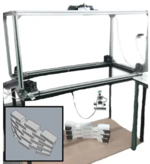
Fig. 1 The layout of the SPIDERobot. The example of an architectural project is depicted in theleft–bottom side
in the mobile platform through an universal joint (hence, the claw is always parallel to the floor and independently of the platform position).
More conventional approaches use only the tension/length of each cable for controlling the Cartesian position (XYZ) of cable-driven robots which has several disadvantages regard-ing to the scalability of the solution. On a contrary, the proposed control acts directly in the cable’s length by using visual information and hence it does not require the feed-back of the tension value. This prototype was developed for assembling architectural projects (see left–bottom corner of Fig.1).
The SPIDERobot is installed in a frame with 1.20×0.6×
1.35 m
3, and its platform can be approximated to a single
point in space since all cables passes through the platform and converge to the center mass. At the highest level, this robot picks parts with different orientations and drops those parts into the environment— according to the executing order of the project (which is usually a set of sequential dropping points).
As can be noticed in Fig.1, the XYZ position of the mov-ing platform (40×30×15 mm3) is obtained by rolling and
unrolling each cable, using servo motors with encoders. A global vision system based on a RGB-D camera computes the current position of the mobile platform, as well as, it detects the parts that might be available in the environment. In addition, this perceptual capability enables the robot to determine an optimal trajectory that minimizes the traveling distance and the risk of colliding with stationary obstacles. This information is crucial during the construction of the architectural project because it is used to control the
move-ment of the robot while avoiding the undesirable release of cables, see Sect.3.3.
3.1 System architecture
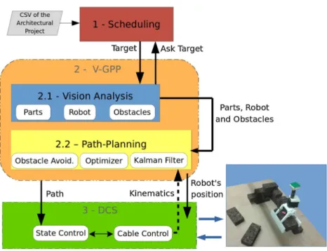
The system architecture of the SPIDERobot is depicted in Fig.2, and it is formed by three distinct modules: scheduling, V-GPP and DCS. First, the schedule module interprets the project and defines a sequential set of dropping points that decompose the architectural structure into executing orders (picking, transporting and dropping parts).
The schedule module manages the execution of the project over time, until the project be successfully completed. It analyses all parts that could be picked and selects the best one by considering the Euclidean distance between the robot and the part along with the target position (location where the part will be dropped). Moreover, it determines the parts that are already in place to avoid wrong picking operations. Before that, the V-GPP module analyses the working environment and generates a collision-free path, which is a path between the robot and the target (picking or dropping position) that guarantees the safeness of the working area. The DCS controller dynamically corrects the position of the robot, as well as, the safe rolling/unrolling of cables based on the kinematics model and the location of the robot that is determined by the visual perception of the V-GPP. The archi-tecture depicted in Fig.2assures a suitable and interactive construction of the project because the V-GPP is constantly analyzing parts that might be available in the working area at arbitrary poses while the DCS enables a precise and accurate navigation. Therefore, the biggest advantage of this archi-tecture is related to the generalization of the entire robotic solution proposed in this research because it can be scaled up to more realistic dimensions without significant changes.
3.2 Dynamic controlling system
Fig. 2 Global System Architecture of the SPIDERobot cable-driven robot
The mathematical expressions of the kinematics model of the SPIDERobot can be found inMoreira et al.(2015). In this way, the method is formed by two control loops. An inner loop corrects the positioning based on the visual location of the robot and, the outer loop compensates possible drifts in the cable lengths. For handle with the releasing problem, the DCS (inner-loop) requires to estimate the cable lengths based on the vision location in order to determinate the esti-mation error that is obtained by the encoder of each motor (kinematics model). A outer-loop measures the error between the desired and the real position of the moving platform. The resulting error is combined with the contribution obtained by the inner-loop that signals the motors (after a PID controller). The behavior of the DCS is evaluated with the V-GPP in Sect.4.1. The interaction between both modules produces a stable behavior, high repeatability and a safe approximation of the claw to each part.
3.3 Vision-guided path-planning system
In general, the V-GPP analyses the environment and esti-mates a collision-free path. A calibrated RGB-D camera is placed on top of the frame which optimizes the field of view and provides distance and texture information of the elements that belong to the scene: parts, obstacles (set of parts already in place) and robot. These elements define the world model which is used to estimate the collision-free path.
A flow diagram of V-GPP is depicted in Fig.3. It is formed by four major stages: localization of the robot, detection of parts, surface reconstruction and path-planning. First, the system determines the current localization of the robot by
segmenting the color of the image. The top color of the mov-ing platform (green) is segmented in the YCrCb color space since the channels Cr and Cb are more invariant to illumina-tion changes (Pinto et al. 2014). Then, the contours obtained by this segmentation are filtered according to the area and connectivity. This originates a robust segmentation of the moving platform to illumination changes (caused for instance by light flickering). The accurate position of the robot is extracted from the depth data. Afterwards, the scene is ana-lyzed in more details to find parts that might be available at the environment. The location of these parts is based on depth and RGB sensors through color, contour and shape segmen-tation. The parts available in the environment are detected very efficiently because the ground plane is removed from the depth information (though a previous calibration proce-dure) which causes regions in the depth data that could only contain parts or the robot (whose location is known). The regions are discretized in height creating several occupancy layers. The upper layer for each region is analyzed and the contours and corners are obtained. Analyzing the aspect ratio of that information makes it possible to detect parts grouped together (since that all parts have the same dimensions). This procedure limits the analysis to a small portion of the point-cloud and accelerates the extraction of parts. Moreover, this methodology makes it possible to determine the pose of parts using data from the RGB sensor (the gradient is used to con-firm if the part detected by the depth verification is a true part), and complemented by information acquired from the depth sensor.4After the parts being detected, their estimative
4 The color segmentation provides a better definition of parts since the
Fig. 3 Schematic flow diagram of the V-GPP system
can be merged by matching the position and orientation in a common world reference to provide an accurate estimation of the parts’ location. It is important to notice that, a part is not detected if it stays under the robot - occlusion prob-lem - and, therefore, the scene will be investigated with the exception of the area surrounding the robot.
Moreover, the environment is reconstructed into a 3D map, by using the data acquired from the depth sensor and the location of the robot. In this way, the V-GPP updates the 3D surface in a continuous manner and, in consequence, the world model enables a faithful characterization of the work-ing conditions which supports the estimation of the closest collision-free path.
As already stated, the information contained in the world model is essential for the path-planner, see Fig.3. In this phase, the trajectory of the robot depends on the 3D surface, the initial position of the robot, the target location and the displacement of the cables during the path. The A-star algo-rithm is the core of the path-planner of the V-GPP. The A-star is one of the most used heuristics to determine paths since it is computational efficient. This is of extremely importance since this research aims to provide a vision-guided technique for a realistic robotic application with the ability to analyze the environment and to predict a suitable path in the shortest time.
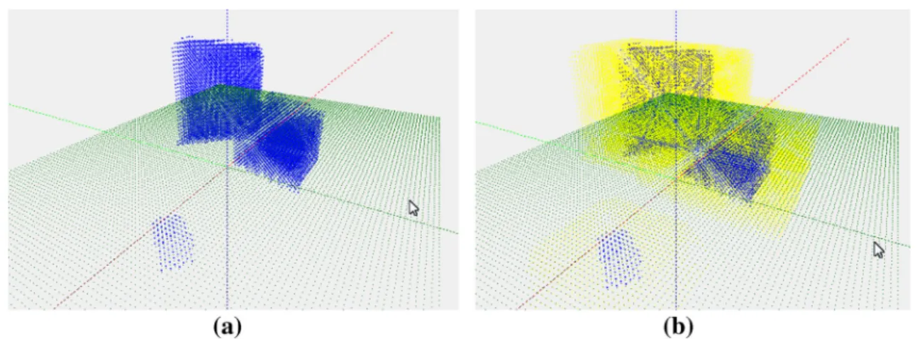
In this path planning the first step to determine the path is to reconstruct the environment by creating a Gridmap. The Gridmap is a set of cells in 3D with the world model. Each cell contains information, whether it is occupied or not by obstacles as shown in Fig.4a. Each cell has a dimension of 0.01 m that was set in accordance to the error of the visual
perception of the environment during the characterization of the world model. The robot is considered a point in the A-star cells, so obstacles have to be extended as shown in the Fig.4b—the yellow points (Costa et al. 2009).
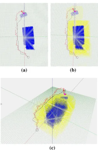
Fig. 4 Results for different views of Scene 2: over the obstacle path.aPerspective view.bTop view
Fig. 5 Collision avoidance of cables. a Restriction zone. bWorld model representation
the DCS will use this information to control the trajectory of the SPIDERobot during the execution of this path (avoiding collisions with the environment).
Finally, the position given by the visual perception is enhanced by a Kalman filter, which resorts to the information of the kinematics model. This provides a more stable posi-tion during the navigaposi-tion. This posiposi-tion should be stabilized
to make the DCS module more immune to the noise of the vision sensor.
4 Results
A comprehensive set of experiments were conducted as part of this work. They aim to analyze and understand the behav-ior of the system architecture of Sect.3and the performance of the V-GPP. All experiments were conducted using the SPI-DERobot prototype in several construction scenarios and all parts were available in the environment at unknown places for the robot. These trials depict real testing conditions which means that the visual system of the mobile robot is sub-jected to different lights conditions, reflections, diffractions and shadows.
The results in this section were obtained with an i7 2.2 GHz computer and without parallel programing or GPU. The methods were implemented in C++ using the commonly used OpenCV library.5 The RBGD sensor was the Kinect One (Pinto et al. 2015) which provides RGB images with a resolution of 1080 p and depth images with a resolution of 512×424. The visual system was (intrinsic and extrinsic)
calibrated in the mechanical structure depicted in Fig.1. The ground truth positions of the objects were manually mea-sured with a millimeter precision relatively to the 3D center mass of each object (0.12×0.06×0.03 m
3whose weight is
about 0.100 kg) which is easy to obtain due to its
rectangu-lar shape. The coordinates are described in a common world reference (according to the extrinsic calibration of the vision sensor).
The first experiments of Sect. 4.1 focus on testing the accuracy of the visual-based positioning, in particular, the interactions between the V-GPP and the DCS. The second experiments demonstrate the ability of the V-GPP to
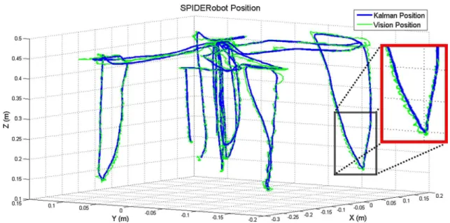
Fig. 6 Position of the SPIDERobot given by the vision module and during the pick-and-place of 4 parts. Coordinates are described in the world reference
pret the environment (parts and robots locations and the 3D surface reconstruction) and the ability of the robot to avoid obstacles, see Sect.4.2. Finally, Sect.4.3presents a demonstration of an architectural construction made by the SPIDERobot.
4.1 Vision-based positioning of the robot and scene understanding
Several experiments were made to validate the positioning system of the robot, especially, the interaction between the V-GPP and the DCS. Each experiment is formed by a real scenario where the robot picks 4 stacked parts at the origin of the world reference6and drops those parts in pre-defined positions. These dropping positions reflect different quad-rants in the world reference and a trial example can be found in video.7
The first evaluation is presented in Fig.6which shows the evolution of the position of the robot based on the vision mod-ule (green line) and based on the Kalman filter (blue line). This Kalman filter combines the visual information with the kinematics model of the robot. In that figure, it is clearly noticeable that the Kalman filter smooths the trajectory of the robotic platform: the position given by the Kalman filter is more immune to sudden variations than the visual esti-mative. This behavior is desired due to the fact that these variations are a consequence of the limited camera resolu-tion, as well as, the error of the depth measure. These trials made clear that the SPIDERobot has different performances
6Parts were placed all stacked with unknown position and unknown
orientations.
7Trial for the 4 drops:http://youtu.be/6iKkZ7Rqvls.
Table 1 Precision analysis for the pick-and-place operations: dropping positions (manually measured) when compared to the expected posi-tions
Desired location Real location
X Y Z X Y Z
−0.15 0.12 0.015 −0.144 0.115 0.015
−0.15 −0.12 0.015 −0.15 −0.135 0.015 0.15 −0.12 0.015 0.154 −0.135 0.015 0.15 0.12 0.015 0.157 0.109 0.015 These results are related to Fig.6
when a Kalman filter is considered, meaning that the motion of robot is more stable when the filter is used. In this sce-nario, the movements of robot have suffered lower vibrations and, therefore, the disturbances in the navigation path were reduced.
This reflects an important advantage of combining the DCS with the V-GPP since the accuracy of the robot’s motion during the navigation is increased. Next, the precision of the pick-and-place operations is analyzed which is a relevant feature during the construction of architectural projects. It is possible to see in Table1the desired dropping position and the true location where the parts were dropped.
The previous experience was made for different levels of the pile of parts. In these trials, a list of drop positions is created and, at the end of each trial, the position of the part’s center of mass is measured. From this set of trials, the Euclid-ean error was in average 0.015 m, with a standard deviation of
0.005 m—see Table2. This table demonstrates two results:
Table 2 Error analysis of 15 trials with 4 measures each: global posi-tioning error of the SPIDERobot and the error of the vision-based localization module of the V-GPP (manually measured)
Error Global (m) Vision (m)
Average 0.015 0.006
Standard deviation 0.005 0.002
Maximum 0.024 0.012
Minimum 0.003 0.001
Fig. 7 An example of the visual detection of parts and the moving platform, conducted by the V-GPP module proposed in this research
of the V-GPP. As can be noticed, the localization of the robot given by the V-GPP is quite accurate since the error is about 0.006 m. However, the DCS controller causes an additional
error due to positioning tolerances that are required to achieve smoother movements. These results show that the proposed prototype looks to be promising since the maximum over-all error is less than 0.024 m and, obviously, more reliable
sensors and actuators would made possible to achieve better results.
The next result demonstrates the detection of parts and the localization of the robot that is accomplished by the V-GPP. Figure7shows the identification of parts (some were placed at arbitrary locations and the others were already dropped by the robot) and the location of the platform, represented by purple points and a small red circle, respectively. The orien-tation and the boundary of parts are also highlighted - parts visually obstructed are not represented because only parts at the upper level can be accessed by the robot. Moreover, the luminosity level of the scene is not homogeneous and, thus, the vision system implemented as part of the V-GPP is capable of detecting the parts and the robotic platform correctly.
Fig. 8 Results for different views of scene 1: Aside the obstacle path.
Thewhiteandpurple circledepict the initial and final position of the
path, respectively.The yellow pointsare the dilate areas for the obstacle avoidance andthe green pointsrepresent the ground plane.aWithout dilate areas view.bTop view.cPerspective view
4.2 Obstacle avoidance
Besides its ability to locate parts as well as the robot, the V-GPP also provides a path-planning capability that avoids collisions between the moving platform or cables with the environment. A set of trials conducted for three different scenarios8make possible to validate the path-planning algo-rithm, especially, the generation of the collision-free path and the controllability of the DCS during the execution of the tra-jectories. These three testing scenarios include: (1) obstacles in one side, (2) climbing a wall and (3) obstacles in both sides.
The first two scenarios are analyzed in more details. Fig-ures8and9provide a visual representation of both testing scenarios. The path estimated by the V-GPP is presented in
8 A video of these experiments can be seen inhttps://www.youtube.
Fig. 9 Results for different views of scene 2: over the obstacle path.The whiteand
purple circledepict the initial
and final position of the path, respectively.The yellow points
are the dilate areas for the obstacle avoidance and the
green pointsrepresent the
ground plane.aWithout dilate areas view.bTop view.d Perspective view
Table 3 Initial and final positions of the path generated by the V-GPP
Scene Initial position (m) Target position (m) Max. error (m)
Xi Yi Zi Xt Yt Zt
Scene 1 0.328 0.06 0.22 −0.39 −0.014 0.082 0.010
Scene 2 0.39 0.11 0.13 −0.30 −0.076 0.1 0.009
The maximum absolute error obtained during the navigation of the robot
black dots while the path really followed by the robot is showed in red dots. The blue dots represent the obstacles (for instance, a wall) and the initial and target positions are marked with gray and pink, respectively. Yellow dots are the reserved space around the obstacle to avoid collisions. Table3presents the initial and the target positions for both scenes, whereXi,Yi and Zi is the initial position whereas
Xt,YtandZt is the target position.
The first scenario is composed by an obstacle between the robot and the part to be picked. The path planner cre-ated a safe trajectory to contour this large obstacle, see Fig.8 (with different perspectives). The second scenario evaluated the ability of the V-GPP to generate more complex paths
(requiring movements along all directions), see Fig.9. In this experiment, the objects of the environment have forced the algorithm to prepare a path over the lower obstacle that turns left after passing by the higher object. As can be noticed in Table3, the maximum error between the planned trajectory and the trajectory performed by the SPIDERobot was about 0.010 and 0.009 for the first and second experiment,
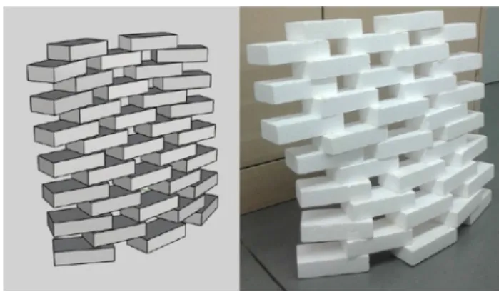
Fig. 10 The project of a wall in CAD (on the left) and the wall that was obtained by the SPIDERobot (on the right)
significantly lower than the dilation volume considered by the path-planner.
As can be seen, the path planning estimates a collision-free path that allows the robot to manipulate a part from the initial to a target position and, without colliding with any element belonging to the environment. The average processing time to find the path based on the A-star algorithm is about 2 ms and it requires 755 ms to setting up the map based on the world model definition.
4.3 Construction of a wall: demonstration
The major objective of the SPIDERobot robot is to be able to construct an architectural project, previously idealized by a CAD instrument. This section presents a real demonstration of the robot’s capabilities on this subject. Figure10(on the left) represents the example of one project that could be real-ized by the SPIDERobot (on the right). Due to the limitations of the workspace where the robot is currently installed, this wall project was constructed in two parts and then assembled together. The construction of the first half of this wall can be found in the a video.9
5 Conclusion
The research in this paper proposed the SPIDERobot which is a 4 DOF (one of them is given by the claw rotation) cable-driven robot. This robot is not controlled by a tensor-feasible approach and resorts to visual information to control its navigation. Thus, a Vision-Guided Path-Planning Sys-tem (V-GPP) determines a collision-free path that should be executed by the motion control. The V-GPP has a visual module that localizes the robot using RGB-D information and the kinematics model, merged by a Kalman filter. This vision module is also capable of understanding the
envi-9http://youtu.be/JrSkPFtTvDo.
ronment and to find the parts available for picking. This information defined a world model that is used by the obsta-cle avoidance. A set of experiments demonstrate that the robot achieved a positioning accuracy of 0.015 m and a
localization precision around 0.006 m. Therefore, results
indicated that the proposed architecture enables the robot to navigate along the environment while avoiding obsta-cles. In this way, this robotic prototype can be scaled up to realistic environments without significant changes in the software architecture. In a realistic construction site, the mechanic structure of the robot should be redesigned in order to contemplate the pick-and-place of different objects (dis-tinct sizes and shapes). This topic is not contemplated in this current robot however, a possible solution could be the usage of distinct claw configurations that are autonomously attached/detached by the moving platform (depending on the type of objects).
Acknowledgements This work is partly funded by the project PTDC/ ATP-AQI/5124/2012 - Robotic Technologies for Non-Standard Design and Construction in Architecture. This work is also financed by the ERDF European Regional Development Fund through the COM-PETE Programme (operational programme for competitiveness) and by National Funds through the FCT Portuguese Foundation for Science and Technology within project “FCOMP - 01-0124-FEDER-022701”.
References
Aoude, G., Luders, B., Joseph, J., Roy, N., & How, J. (2013). Proba-bilistically safe motion planning to avoid dynamic obstacles with uncertain motion patterns.Autonomous Robots,35(1), 51–76. Bhattacharya, S., Likhachev, M., & Kumar, V. (2012). Topological
con-straints in search-based robot path planning.Autonomous Robots,
33(3), 273–290.
Borgstrom, P., Jordan, B., Borgstrom, B., Stealey, M., Sukhatme, G., Batalin, M., et al. (2009). Nims-pl: A cable-driven robot with self-calibration capabilities.IEEE Transactions on Robotics,25(5), 1005–1015.
Borgstrom, PH., Borgstrom, NP., Stealey, MJ., Jordan, B., Sukhatme, G., Batalin, MA., & Kaiser, WJ. (2008). Generation of energy efficient trajectories for nims3d, a three-dimensional cabled robot.
InIEEE International Conference on Robotics and Automation
(pp. 2222–2227), IEEE.
Bosscher, P, I. I., RLW, Bryson, L. S., & Castro-Lacouture, D. (2007). Cable-suspended robotic contour crafting system.Automation in
Construction,17(1), 45–55. doi:10.1016/j.autcon.2007.02.011.
Costa, P., Moreira, A. P., & Costa, P. G. (2009). Real-time path planning using a modified a* algorithm. InConference on mobile robots and
competitions(pp. 222–227).
Dallej, T., Gouttefarde, M., Andreff, N., Dahmouche, R., & Martinet, P. (2012). Vision-based modeling and control of large-dimension cable-driven parallel robots. In2012 IEEE/RSJ international
con-ference on intelligent robots and systems (IROS)(pp. 1581–1586).
Gagliardini, C., & Gouttefarde, G. (2015). Optimal path planning and reconfiguration strategy for reconfigurable cable-driven parallel robots. InIEEE international conference on robotics and automa-tion (ICRA).
German, J., Jablokow, K. W., & Cannon, D. J. (2001). The cable array robot: Theory and experiment.IEEE International Conference on
Gouttefarde, M., Daney, D., & Merlet, J. P. (2011). Interval-analysis-based determination of the wrench-feasible workspace of parallel cable-driven robots.IEEE Transactions on Robotics,27(1), 1–13. doi:10.1109/TRO.2010.2090064.
Hastak, M. (1998). Advanced automation or conventional construction process.Automation in Construction,7(4), 299–314. doi:10.1016/ S0926-5805(98)00047-8.
Julia, M., Gil, A., & Reinoso, O. (2012). A comparison of path planning strategies for autonomous exploration and mapping of unknown environments.Autonomous Robots,33(4), 427–444.
Korayem, M. H., Tourajizadeh, H., Zehfroosh, A., & Korayem, A. H. (2014). Optimal path planning of a cable-suspended robot with moving boundary using optimal feedback linearization
approach-ing.Nonlinear Dyn.,78(2), 1515–1543.
Lahouar, S., Ottaviano, E., Zeghoul, S., Romdhane, L., & Ceccarelli, M. (2009). Collision free path-planning for cable-driven parallel robots.Robotics and Autonomous Systems,57(11), 1083–1093. doi:10.1016/j.robot.2009.07.006.
Moreira, E., Pinto, A. M., Costa, P., Moreira, A. P., Veiga, G., Lima, J., Sousa, J. P., & Costa, P. (2015). Cable robot for non-standard architecture and construction: A dynamic positioning system. In
IEEE International Conference on Industrial Technology (ICIT)
(Vol. 1, pp. 3184–3189), IEEE.
Mourad Ismail, LR Lahouar Samir. (2013). Dynamic in path planning of a cable driven robot. InDesign and modeling of mechanical
systems. Lecture notes in mechanical engineering(pp. 11-18).
Oh, S. R., & Agrawal, S. (2006). Generation of feasible set points and control of a cable robot.IEEE Transactions on Robotics,22(3), 551–558.
Ottaviano, E., Ceccarelli, M., & De Ciantis, M. (2007) A 4-4 cable-based parallel manipulator for an application in hospital envi-ronment. InMediterranean conference on control automation(pp 1–6).
Pinto, A., Costa, P., Moreira, A. P., Rocha, L. F., Veiga, G., & Moreira, E. (2015). Evaluation of depth sensors for robotic applications. In
2015 IEEE international conference on autonomous robot systems
and competitions (ICARSC)(pp. 139–143).
Pinto, A. M., Moreira, A. P., Correia, M. V., & Costa, P. G. (2014). A flow-based motion perception technique for an autonomous robot system.Journal of Intelligent and Robotic Systems,75(3), 475– 492.
Trevisani, A. (2010). Underconstrained planar cable-direct-driven robots: A trajectory planning method ensuring positive and bounded cable tensions.Mechatronics,20(1), 20–44.
Usher, K., Winstanley, G., & Carnie, R. (2005). Air vehicle simula-tor: an application for a cable array robot. InIEEE international
conference on robotics and automation (ICRA)(pp. 2241–2246),
IEEE.
Vh, P., Heikkil, T., Kilpelinen, P., Jrviluoma, M., & Gambao, E. (2013). Extending automation of building construction survey on poten-tial sensor technologies and robotic applications.Automation in
Construction,36, 168–178. doi:10.1016/j.autcon.2013.08.002.
Yu, H., & Beard, R. (2013). A vision-based collision avoidance tech-nique for micro air vehicles using local-level frame mapping and path planning.Autonomous Robots,34(1–2), 93–109.
Andry Maykol Pinto received his degree in Electrical and Computer Engineering from the Faculty of Engineering of the University of Porto (FEUP) in 2005, and his Ph.D. from the Department of Electrical and Computer Engineering of FEUP, Portugal, in 2014. Cur-rently, he is a researcher at the Robotics and Intelligent Systems Unit of INESCTEC (Technol-ogy and Science Associate Lab-oratory) and he is working in visual motion perception, motion analysis, optical flow, unsupervised segmentation, data fusion tech-niques and underwater perception.
José Lima received the M.Sc. and Ph.D. in Electrical and Com-puter Engineering on Faculty of Engineering of University of Porto, Portugal in 2001 and 2009. He joined the Polytechnic Insti-tute of Bragança in 2002, and currently he is a Professor in the Electrical Engineering Depart-ment of that school, where he teaches classes such as embed-ded systems, power electronics and automation. He is also a researcher in Robotic and Intel-ligent Systems group of the INESC-TEC (Institute for Systems and Computer Engineering of Porto, Portugal). He has published more than 50 papers in international scientific journals and conference proceedings such as International Journal of Advanced Robotic Systems, International Journal of Factory Automation, Robotics and Soft Computing, FAIM and ETFA. In addi-tion, he participated in some autonomous mobile robotics. Moreover, his research interests are in the field of robotics and automation: simula-tion, path planning, image processing, localizasimula-tion, navigasimula-tion, obstacle avoidance and perception. Moreover, he participated in some national and FP7 projects such as Produtech, GRACE, ARUM, CARLOS and STAMINA.
José Pedro Sousareceived his degree in Architecture from the Faculty of Architecture of the University of Porto (FAUP) in 1999 and the Master in Genetic Architecture in ESARQ-UIC (Barcelona) in 2002, and his Ph.D. from the IST-UTL (Lis-bon) in 2010. Currently, he is a Professor at the FAUP and he is working in robotic applications for architectural projects.