UNIVERSIDADE DA BEIRA INTERIOR
Engenharia
Effects of Design Parameters on Damping of
Composite Materials for Aeronautical Applications
João Pedro dos Santos Lopes
Dissertation for the Degree of Master of Science in
Aeronautical Engineering
Supervisor: José Miguel Almeida da Silva, PhD
Co-supervisor: Pedro Vieira Gamboa, PhD
Acknowledgments
I would like to express my sincere gratitude to my parents, who were tireless during all these University years providing me the possibility to study far away from home and in a course which I really love.
A very special kind of gratitude to Professor José Miguel Silva, my academic supervisor, for his support and guidance both in my thesis and in the parallel scientific works. Moreover, for his classes in aerospace structures and materials, which have inspired me to develop this thesis in the area of composite polymers and vibration control.
To Professor Pedro V. Gamboa, my co-supervisor, for his assistance and suggestions, and also, not less important, for all the provided laboratory conditions and material.
To Professors Ricardo Claudio and Nuno Nunes, from Instituto Politécnico de Setúbal, for their attention, time and support during the experimental works, as well as their receptiveness during the time I spent in IPS.
And a sincere acknowledgement to Filipe Couceiro (PhD student) and Alejandro Píriz (former MSc student) for their help during my thesis work. I hope to return their support one day!
Dedicated to my Professors, to my Parents and Family and to my unforgettable University friends!
Abstract
Many engineering projects have shown a great concern with the dynamic response of generalized mechanical systems where a set of rigorous demands are placed on the design of structures in sectors such as the aerospace or the automobile industries. Aerospace materials, for example, in most cases have been developed for a specific purpose, like some particular metal alloys and composites. It is their operation requirements that influence the optimization of certain intrinsic mechanical or physical properties.
The dynamic behaviour of a structure can be refined by anticipating any performance-related problem during the design process, where vibration and others parameters can be measured and optimized for the desired applications. It is often desirable to be able to predict accurately the dynamic response of a structure under certain excitation conditions. Given that, it is necessary to understand how its mass, stiffness or damping properties could be modified to obtain a desired response and vibration control, taking into account structural margin of safety and life-time limits under service. Thus, the damping of such structures, which is associated to the energy dissipation capacity, is a key aspect regarding the fatigue endurance and noise/vibration control as it controls the amplitude of resonant vibration response.
Envisaging to create a cheaper, direct and maintenance-free alternative to active damping systems, passive methods are a straightforward solution for certain industrial demands. In fact, active damping systems typically imply more structure weight, considerable energy consumption, reliability issues and limited strain/force response, which are undesired features in general technological applications, especially in the aerospace sector. To achieve high damping properties discarding the use of an active system, the use of some isolation techniques, the inclusion of high damping materials or even the need for physical structural modifications are often necessary in the standpoint of a new component’s development for passive control applications. As an example, in most recent investigations, co-curing/embedded viscoelastic damping constituents in composites has been a successful way to increase the damping capacity.
In the context of the present work, a passive damping treatment method based on cork utilization as viscoelastic material has been used to improve the damping properties of fiber-reinforced composites. A numerical and experimental study was made to predict and understand the benefits of such method and characterize any inherent effects on modal loss factor and respective structural natural frequencies regarding the use of cork. The excellent energy absorption properties of cork under static and dynamic loading conditions, its lightness, near-impermeability and lower thermal conductivity, are the base of a recent and
crescent interest in aeronautical, railroad and automobile applications for cork based materials. These intrinsic characteristics are also the main reasons for considering it as viscoelastic layer applicable in passive damping treatments with a great potential for vibration control in future aerospace applications.
As far as the numerical study concerns, a finite element model (FEM) was developed to analyze the main dynamic properties of the composite structure samples, for example, the modal frequencies and respective loss factors, and compare it with the experimental results, allowing to assess the accuracy of numerical data. Distinct design variables were considered to determine their influence in the loss factor variation, namely: damping layer thickness and its relative position within the laminate, number of viscoelastic layers and effect of different layup stacking sequences.
Results are encouraging about the possible use of cork based composites as a viable passive solution to improve the damping properties of high performance composites, giving rise to an increase of the loss factor as well as a change of the natural frequencies of the structure according to the design requirements for particular applications.
Keywords
Resumo
A resposta dinâmica de sistemas mecânicos revelou ser de grande preocupação em vários projectos de engenharia onde existe um conjunto rigoroso de exigências ligadas ao projecto de estruturas, tal como acontece em particular na indústria aeroespacial e automóvel. Materiais aeroespaciais, por exemplo, foram em muitos dos casos desenvolvidos tendo em conta propósitos específicos, tais como algumas ligas metálicas e alguns compósitos. São os requisitos de operação que influenciaram a optimização de certas propriedades mecânicas ou físicas desses materiais.
O comportamento dinâmico de uma estrutura pode ser refinado durante o processo de projecto antecipando qualquer problema relacionado com o respectivo desempenho, onde vibrações e outros parâmetros podem ser medidos e posteriormente optimizados tendo em conta as aplicações desejadas. É preferível ter capacidade para prever com precisão a resposta dinâmica de uma estrutura exposta a determinadas condições de vibração. Posto isto, é necessário entender como é que a respectiva massa, rigidez ou as propriedades de amortecimento podem ser modificadas de forma a obter um controlo desejado de comportamento e vibração, tendo em conta as margens de segurança e limites de vida útil estruturais durante a sua operação. Assim, o amortecimento de tais estruturas, que está associado com a capacidade de dissipação de energia, é um aspecto chave relativamente à resistência à fadiga e no controlo de ruido/vibração traduzindo-se na forma como é controlada a amplitude de resposta em vibrações de ressonância.
Pretendendo criar uma alternativa ao controlo de vibrações activo mais barata e com pouca necessidade de manutenção, os métodos passivos apresentam-se como uma solução directa a algumas necessidades da indústria. De facto, a aplicação de sistemas activos tipicamente implica mais peso estrutural, um considerável consumo de energia, problemas de reabilitação e uma resposta deformação/tensão limitada, as quais são características indesejadas para as aplicações tecnológicas gerais, especialmente para o sector aeroespacial. Para conseguir melhores propriedades de amortecimento descartando o uso de um sistema activo, o uso de algumas técnicas de isolamento, a inclusão de materiais de alto amortecimento e até a necessidade de modificações físicas e estruturais são frequentemente necessárias no ponto de vista de o desenvolvimento de um novo componente para aplicações de controlo passivo. Como exemplo, investigações recentes apresentam certos compósitos pós-curados com camadas viscoelásticas embebidas como uma forma bem sucedida de aumentar as capacidades de amortecimento.
No contexto do trabalho presente, um método de tratamento de amortecimento passivo baseado na utilização da cortiça como um material viscoelástico foi utilizado para melhorar
as propriedades de amortecimento de compósitos com fibras de reforço. Foi então elaborado um estudo numérico e experimental para prever e entender os benefícios de tal método caracterizando qualquer efeito inerente no factor de perda e nas respectivas frequências naturais estruturais. As excelentes propriedades de absorção de energia por parte da cortiça sobre condições de carregamentos estáticos e dinâmicos, a sua baixa densidade volumétrica, quase impermeabilidade e baixa condutividade térmica, são a base de um recente e crescente interesse da sua aplicação precisamente no sector aeronáutico, ferroviário e automóvel.
Em relação ao estudo numérico, um modelo de elementos fintos (MEF) foi desenvolvido em
software para analisar as principais propriedades dinâmicas de provetes feitos em
compósito, como por exemplo as frequências modais e respectivo factor de perda, comparando-as posteriormente com os resultados experimentais permitindo então classificar a precisão dos dados numéricos. Distintas variáveis de projecto foram consideradas para determinar a sua influência na variação do factor de perda, nomeadamente: a espessura da camada viscoelástica e a sua posição relativa no laminado, o número de camadas viscoelásticas e o efeito das diferentes sequências de empilhamento.
Os resultados são optimistas em relação à possibilidade do uso da cortiça em compósitos como um método passivo viável tendo em conta o aumento do factor de perda bem como na modificação das frequências naturais da estrutura de acordo com os requisitos de projecto de cada aplicação.
Palavras-chave
Contents
Acknowledgements……….... iii Abstract………. v Resumo……… vii Contents………. ix List of Figures……… xi List of Tables………. xv Nomenclature……… xvii Chapter 1 – Introduction………. 11.1 – Motivations for studding damping in composites and viscoelastic materials……. 1
1.2 – Objectives………. 3
1.3 – Thesis structure……….. 3
Chapter 2 – Bibliographic Review……….. 5
2.1 – Vibration control in composites………. 5
2.1.1 –Active control versus passive control………. 6
2.2 – Introduction to viscoelastic materials……….. 8
2.2.1 – Basic concepts………. 8
2.2.2 – Viscoelastic materials behaviour………. 9
2.2.3 – Linear viscoelastic response – Mathematical models.………. 15
2.2.4 – Viscoelastic frequency dependence: Numerical model………. 20
2.2.5 – Vibration theory applied to viscoelastic materials………. 22
2.3 – Damping on sandwich structures with viscoelastic constrained layer………. 25
2.3.1 – Ross-Kerwin-Ungar damping model………. 26
2.3.2 – Direct frequency response technique……….. 28
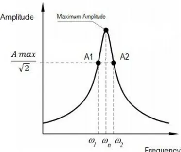
2.4 – Half-power bandwidth method for modal data extraction……… 29
2.5 – Advantages of using CFRP and cork for aerospace applications……….. 30
Chapter 3 – Numerical Model……….. 35
3.1 – Introduction………. 35
3.2 – Material and configuration………. 36
3.2.1 – Laminate preparation and experimental set-up……….…. 39
3.3 – Mesh……….. 41
3.4 – Model validation………. 42
Chapter 4 – Results………. 45
4.1 – Design parameters effects on loss factor……… 45
4.1.2 – Effect of laminate’s thickness……….. 47
4.1.3 – Effect of the viscoelastic layer relative thickness……… 48
4.1.4 – Effect of the viscoelastic layer relative position……… 50
4.2 – Vibration response……… 52
4.3 – Summary of results………. 54
Chapter 5 – Conclusions……… 55
References……… 57
Annex A - Experimental versus Numerical results plots………. 60
Annex B - Dynamic response in frequency domain plots………. 65
Annex C – Scientific Papers ………. 67
C.1 - A Passive Approach to the Development of High Performance Composite Laminates with Improved Damping Properties………. 67
C.2 - Optimization of the Damping Properties of CFRP Laminates with Embedded Viscoelastic Layers………. 68
List of Figures
Figure 1 – Volume of structural composites application in military and civil aerospace
production over the last decades………. 1
Figure 2 – Exemplar flowchart of an active damping system………. 7
Figure 3 – Elastic versus Viscoelastic material strain behaviour in time domain during cyclic stress loading………. 10
Figure 4- Stress–strain plots comparison for viscoelastic and elastic-plastic materials under constant strain rate [20]……….. 11
Figure 5 - Typical stress-strain behaviour in viscoelastic materials……….. 11
Figure 6 - Typical viscoelastic curve response resulting from a creep-recovery test [20]…… 12
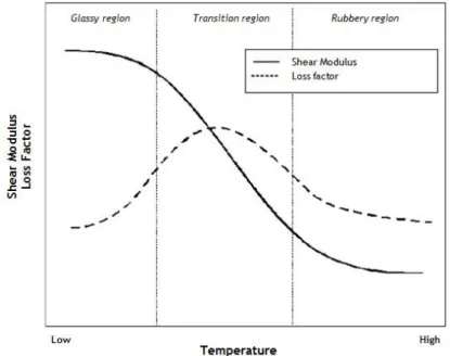
Figure 7 - Temperature effects on complex modulus and loss factor……… 14
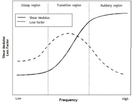
Figure 8 - Frequency effects on complex modulus and loss factor...……….……. 15
Figure 9 - Mathematical models for viscoelastic response……… 16
Figure 10- Types of cores used in sandwich components [34]……….. 25
Figure 11- Schematic representation of the sandwich laminate considered for the analytical analysis………. 26
Figure 12 - Numerical prediction of the loss factor based on the real part of the response spectrum [40].……… 29
Figure 13 – Half-power bandwidth method………. 30
Figure 14 - Specific strength and stiffness comparison between different metals and alloys (quasi-isotropic glass fiber reinforced plastic (Glass/QI) and quasi-isotropic carbon fiber reinforced plastic (Carbon/QI)) [41]……….……….. 31
Figure 15 - Materials used in the new Boeing 787 (with a clear prevalence of CFRPs)……….. 31
Figure 16 - Example of cork application in the propulsion system of Space Shuttle [45]……. 33
Figure 17 – Lightweight phenolic cork as a thermal protection material used in SCOUT Rockets [45]………. 33
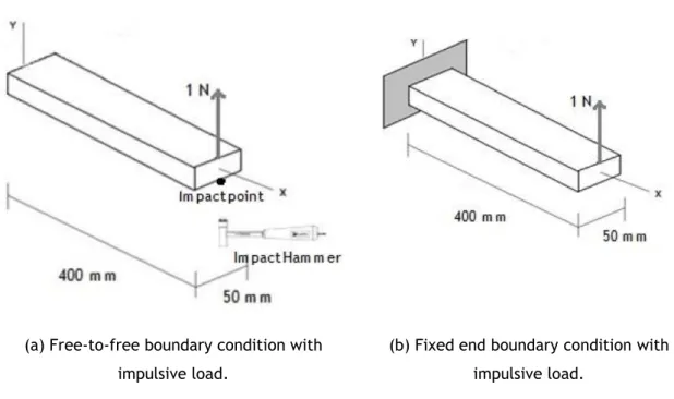
Figure 18 – Illustration of the boundaries conditions and applied load as considered in the numerical model………... 36
Figure 19 – Photos of the laminates’ preparation and some final details………. 39
Figure 20- Schematic representation of the experimental installation……….…. 40
Figure 21 - NL10 used for the experimental set………. 41
Figure 22 – Mesh convergence study for the first resonant frequency (A1 sample)……….……. 42
Figure 23 – Detail of the final mesh after the convergence study……… 42
Figure 24 - Comparison between numerical and experimental data considering two different specimens types……….. 43
Figure 25 – Loss factor variation as a function of layup stacking orientation……… 46
Figure 26 – Loss factor variation as a function of layup stacking orientation for thicker laminates………. 46
Figure 27 – Loss factor variation as a function of the laminate’s thickness……… 47
Figure 28 – Loss factor variation as a function of the viscoelastic layer thickness……… 48
Figure 29 - Analytical vs numerical results regarding the loss factor variation with viscoelastic layer thickness for the first vibration mode……….. 49
Figure 30 - Analytical vs numerical results regarding the loss factor variation with viscoelastic layer thickness for the second vibration mode ….………. 49
Figure 31- Analytical vs numerical results regarding the loss factor variation with viscoelastic layer thickness for the third vibration mode..………. 50
Figure 32 - Loss factor variation as a function of the viscoelastic layer’s relative position (single layer case)………. 51
Figure 33 - Loss factor variation as a function of the viscoelastic layer’s relative position (double layer case)……….. 52
Figure 34 – Dynamic response in frequency domain of specimens A1 and A2……… 53
Figure 35 - Mode shapes obtained from the numerical model for a CFRP + Cork (A2 type with left fixed end)……… 53
Figure A.1 – Numerical and experimental results obtained for type A2……….……… 60
Figure A.2 – Numerical and experimental results obtained for type B1……….………… 60
Figure A.3 – Numerical and experimental results obtained for type B2……….………… 61
Figure A.4 – Numerical and experimental results obtained for type C1……….……… 61
Figure A.6 – Numerical and experimental results obtained for type D1……….….. 62
Figure A.7 – Numerical and experimental results obtained for type E1……….…… 63
Figure A.8 – Numerical and experimental results obtained for type F1……….…… 63
Figure A.9 – Numerical and experimental results obtained for type G1……….… 64
Figure B.1 – Dynamic response in frequency domain of specimens B1 and B2……….. 65
Figure B.2 – Dynamic response in frequency domain of specimens C1 and C2……… 65
List of Tables
Table 1 – Active vs passive damping: advantages and disadvantages…….………. 8
Table 2 – Most common viscoelastic materials used for damping purposes [16]………. 9
Table 3 - Rao correction factors for shear parameter in RKU equations [16]……… 28
Table 4 - CFRP laminates staking sequences………. 38
Table 5 – Mechanical properties of the cork agglomerate core………. 38
Table 6 – Mechanical properties of CFRP laminate……….……... 38
Nomenclature
α Mass proportional damping factor
β Stiffness proportional damping factor
Damping matrix of the system
Mass matrix of the system
Stiffness matrix of the system
Position vector
Velocity vector
Acceleration vector
External load vector
Harmonic response
Eigenvector for each vibration mode
Shear relaxation modulus
Dimensionless shear relaxation modulus Instantaneous shear modulus
Long-term shear modulus
G Shear modulus
Complex shear modulus
G’ Storage shear modulus
G’’ Loss shear modulus
Complex Young’s modulus
E’ Storage Young’s modulus
E’’ Loss Young’s modulus
K Bulk modulus
Instantaneous bulk modulus Long-term bulk modulus Complex bulk modulus
K’ Storage bulk modulus
K’’ Loss bulk modulus
Poisson’s ratio
Complex Poisson’s ratio
Poisson’s dynamic ratio
Poisson’s loss ratio
Corrector factor
EI Flexure rigidity
Stress
Viscosity of the material
Reduced time
Shear modulus Prony series terms
Bulk modulus Prony series terms
i Complex number ( ) ω Frequency t Time Temperature η Loss factor Damping ratio
Specific damping capacity
CFRP Carbon fiber reinforced polymer
FEM Finite element method
RKU Ross–Kerwin-Ungar damping model
Chapter 1
Introduction
1.1 Motivations for studying damping in composites and
viscoelastic materials
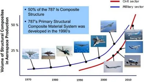
The worldwide aeronautical industry, as many other industrial sectors, is experiencing a restructuring process in order to achieve the efficiency and productivity levels required to meet the challenges of the market demands in the first quarter of the twenty-first century. In the late 60's, carbon fiber became a serious material for lightweight applications. The specific strength and rigidity modulus of high strength fiber composites are higher than other comparable metallic alloys. For the aeronautic industry it means greater weight savings resulting in improved aircraft’s performance, greater payloads, longer range and fuel savings. The first large scale usage of composites in commercial aircraft occurred in 1985, when the Airbus A320 introduced composite horizontal and vertical stabilizers. Airbus has also applied composites in up to 15% of the overall airframe weight for their A320, A330 and A340 family [1, 2]. More recently, the new Boeing 787 is a revolutionary commercial airliner made mostly of carbon composites or super durable plastic representing over than 50 % of the empty weight. However, the use of composites has been more prominent in the military sector, spreading surprisingly to general aviation aircraft in the following decades.
Figure 1 – Volume of structural composites application in military and civil aerospace production over the last decades.
The increased use of composites in aerospace, automobile and railroad sectors revealed a new state of problems regarding their application compatibility with others materials, particularly for vibro-acoustic control. For general aircraft or some spacecraft, vibrations may have several causes: extension and retraction of landing gear systems, deployment of aerodynamic brakes, engine normal operation and normal airflow over the surfaces. Most of these effects are mainly predominant during the take-off and landing phases. Notwithstanding their inevitability, these vibrations must be minimized by appropriate design features through active and/or passive damping treatments in order to improve aircraft performance and reliability levels of structures and systems.
Passive damping treatments in composites as a result of the application of embedded viscoelastic materials (which possess an intrinsic capacity of dissipating mechanical energy) revels to have greater advantages in terms of energy efficiency and reliability of machines/structures compared to active systems. Presently, there are a considerable number of research works concerning noise and vibration control related to aircraft. For example, by improving interior sound quality, aircraft engineers can increase the passengers comfort. Additionally, other problems regarding air traffic increase in urban areas can be minimized by reducing the engines’ exterior noise. For such concerns, materials with damping capabilities used for structural applications, such as the ones with viscoelastic properties, may present a dynamic behaviour that needs a profound knowledge aiming at a better understanding of the their performance under different loading conditions.
In the particular case of passive damping applications in composites via the inclusion of viscoelastic material, studies have been made regarding their use as noise control treatment to reduce noise transmission through automobiles, trains and aircraft fuselage skin panels. This type of damping is also used to decrease the vibro-acoustic response of avionics equipment in typical satellite systems and to maximize the damping capacity of composites used in deployable space structures, such as solar sails, inflatable antennas, inflatable solar arrays, etc. [3, 4].
In the case of this work, a cork agglomerate layer was considered for damping purposes. The reason for considering cork as the viscoelastic material comes from the excellent energy absorption properties of this natural material, which were confirmed in previous works regarding the characterization of cork based composites under static and dynamic loading
conditions [5-7]. For engineering purposes, an analysis or design involving cork agglomerates
with CFRP must incorporate their viscoelastic behaviour, temperature and frequency dependence as well as the dynamic response, which in general is based on experimental and numerical measurements.
1.2 Objectives
The present thesis characterizes the application of a constrained viscoelastic layer in CFRP specimens as a passive damping treatment. Such damping solution may be applied into structures or mechanical systems that are subjected to loads or cycle excitations which may endanger its strength or cause displacements beyond the design point. The damping of such structures is also important in aspects regarding fatigue endurance, noise and vibration control.
In order to predict the best solution for operational purposes, various laminates with different stacking sequences, number of carbon-fiber layers and viscoelastic layer thickness were characterized via FEM analysis (Finite element method) corroborated with experimental results. As referred before, the viscoelastic material was composed by a cork agglomerate,
being necessary to model such material in 6.10-1 software for a numerical analysis.
The FEM analysis was developed in the same software to obtain the main dynamic properties of the structure, such as the natural frequencies and loss factor, as this latter parameter is commonly used as an effective damping evaluator. Experimental testing provided loss factor results for comparison purposes with the numerical data. Results provide useful information about the possible use of cork based composites as a viable passive solution to improve the damping properties of high performance composites, allowing the loss factor evaluation for different laminate’s configuration types.
1.3 Thesis structure
This thesis is structured in five chapters. The present one is an introduction to the core theme of this work and respective objectives are presented.
The second chapter summarizes all the essential thesis bibliographic review based on the state-of-the-art performed in the research phase of the work. The main subjects addressed are composite vibration control methods, general theory of structural vibration, composite sandwich structures, structural damping models, viscoelastic models and some information about the half-power bandwidth method used to estimate the experimental loss factor results.
The numerical model developed in this work is described in the third chapter. There is a description of some fundamental concepts regarding the development of the numerical model based on the finite element method (FEM). The main configurations and geometric dimensions of the plate samples are also described in this chapter, as well as the numerical model mesh
convergence study and the necessary model validation through the comparison between numerical end experimental results.
The fourth chapter presents all numerical results obtained in the course of this work followed by a final parametric optimization of the loss factor based in the design parameters effects on damping. The natural frequencies regarding the first bending modes of each beam were also determined through a modal analysis. Moreover, FEM analysis provides important information about the natural mode shapes and frequencies of the different CFRP laminates. Therefore, the requested numerical output is always analysed in a comparative basis on the dynamic behaviour between specimens with or without viscoelastic layer.
Finally, chapter 5 summarizes the major conclusions and suggests possible paths for further developments in the context of this research line.
Chapter 2
Bibliographical review
2.1 Vibration control in composites
Vibrations can be defined as mechanical oscillations of a system which is displaced from its position of equilibrium. Every object has a different response to excitations depending on material properties, geometry, and boundary conditions. For any material, it is convenient to describe the vibrational response by considering three main parameters: amplitude, vibration mode shape and frequency.
Active and passive damping methods provide fundamental capability to control displacements in dynamic load conditions and to prevent undesired vibrations. Nowadays, transport industries (such as aeronautics, railroad and automobile) use many forms of these two methods for vibration and noise suppression purposes, staring the future in a continuous searching for new solutions regarding important design parameters, like structural weight, material and damping systems costs and others aspects dependent on the type of application. The use of composites increased during the last decade due to some important properties, namely their high strength-to-weight ratios (as a result of the superior strength and stiffness of the reinforcing fibers), great corrosion resistance, improved fatigue life and greater design flexibility for optimum mechanical performance. However, the high stiffness of such materials entails a low damping loss factor, which is a measure of energy dissipation capacity. To achieve high damping properties without the use of an active system (which typically implies more structural weight, considerable energy consumption and limited strain/force response) it is necessary to adopt passive approaches, e.g., physical structural modifications, isolation techniques or the use of high damping materials.
From recent investigations, co-curing/embedded viscoelastic damping materials in composites has been a successful way to increase the damping capacity of composites, compromising however the stiffness and strength of the structure (generally affected with little reductions) [8]. The principle is similar to the conventional constrained layer treatment, where the most part of the damping effect comes from the shear loading induced between the damping layer and the constraining layers. Early studies have concluded that the lay-up sequence and the mode of vibration affect the system loss factor, which have significant dependence when combined with others parameters [9-11]. It is the layer deformation in shear mode that leads to energy dissipation in a more efficient way. In addition, sandwich beams with a viscoelastic core are very effective in reducing and controlling vibration response of lightweight and
flexible structures, because in these cases the viscoelastic material is strongly deformed in shear due to the adjacent stiff layers [2]. In flexural vibrations, for a general case of constrained viscoelastic core layer, the dissipation of energy happens due to shear strain in the core, reducing the overall structure vibration. In the unconstrained layers, like the adjacent layers bonded to the core, the dissipation of energy is by means of extension and compression of viscoelastic layer [3, 13].
Attempting to model such behaviour, the utilization of advanced optimization procedures based in the development of computational models reveals to be an efficient procedure to determine structural damping parameters, such as loss factor or damping ratio. For composites with a constrained viscoelastic layer applied through a co-curing process, the anisotropy of fiber-reinforced constrained layers promotes the damping mechanisms due to the higher capacity of energy dissipation of composites when compared with metallic layers, which are an example of conventional isotropic materials [5, 12]. In general, composite materials, especially carbon fiber reinforced polymers (CFRP), have not a high damping capacity and need some improvements using vibration control methods to optimize the damping properties without neglecting the overall component/system weight. The damping of composites depends on the contribution of several micromechanical, laminate and structural parameters, fiber and matrix ratios, ply angles, ply thicknesses, stacking sequence, curing process, temperature and existing damage or structural defects. Moreover, composite damping is anisotropic, where the maximum energy dissipation is verified in the transverse direction and in shear motion whereas the minimum occurs in the direction of the fibers [13]. Aiming at obtaining significant structural advantages of damping in composite materials, it is very important to use adequate analysis tools, where the variables are the parameters of the laminate for damping optimization purposes. Passive damping has been demonstrated as an essential dynamic and viable method for composite vibration suppression as well as in noise control, fatigue endurance and impact resistance [14, 15], which motivated the adoption of this strategy in the present work.
2.1.1 Active control vs passive control
Active control
Active control is applied, in general, with attached mechanisms and devices, needing an external energy supply enabling the integration of some system sensors to control the structure’s damping response. In some cases, an external real-time data acquisition is required for providing a more efficient and accurate active response of the attached mechanism, presenting itself as a solution that entails more costs and maintenance work. Furthermore, all this equipment means additional mechanical organs and with it, more weight
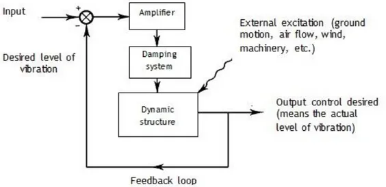
and complexity to the system. Although it is the best and only damping solution for some specific cases, many sectors are searching for alternatives capable to maintain the same safety factors and load requirements. Therefore, there are plenty of situations where passive control is the most effective and efficient way to reduce weight, costs, maintenance works and, furthermore, less probably of system’s failure. However, passive damping is not capable of instant feedback capability in response to a specific stimulus, which implies an automatic adjustment to the required level. Thereby, active control systems remains the best solution to measure specific external inputs and provides an instant feedback response, allowing a continuous desired level of damping, as exemplified in Figure 2.
Figure 2 – Example flowchart of an active damping system.
Passive control
It is clear that there are added costs and complexity with active systems compared to passive control solutions. Passive control refers to energy dissipation based on the use of passive technologies (such as structural joints, supports and isolators) or by integrating a damping material (such a viscoelastic layer) in a host structure, providing internal damping. Passive damping treatments are less expensive to produce than other methods, but their successful application requires a complete understanding of the vibration problem and the properties of the damping candidate materials. Viscous dampers, dynamic absorbers, shunted piezoceramics dampers, and magnetic dampers are other mechanisms of passive vibration control. This type of control is used to eliminate unwanted dynamics in the structure and to achieve a reduction of system disturbance excitation with specific and precise control of some parameters, increasing the overall structural stability. Table 1 presents a short compilation of some damping category materials performance and their pros and cons in passive or active control.
Table 1 –Active vs passive damping: advantages and disadvantages.
Damping material Advantages Disadvantages
Passive damping
Viscoelastic
High Damping
Low weight penalty
No external energy needed
Low costs in production or operation
Unsuitable for very low and high temperatures and at low frequencies
No controllability
Hard damping alloys
High temperature, high frequency operating range
No external effort needed
Relatively low damping
High weight penalty
High strain dependency
No controllability Active damping Piezoelectric, magnetostrictive alloys or composites
Controlled blocking force generation
High or Moderate temperature, high frequency operating range
Low inherent damping in most operating ranges
External energy supply
Instability issues in control
Shape Memory
alloys Large strain applications
Lower controllability
Low frequency bandwidth
Needs either stress or temperature induced phase transformation
2.2 Introduction to viscoelastic materials
2.2.1 Basic concepts
As referred before, a viscoelastic material is an efficient solution for passive damping treatments. Such materials exhibit both viscous and elastic behaviour, and their properties are influenced by different parameters, namely load, time, temperature and frequency. This type of materials dissipate vibrational energy in the form of heat that is generated when the material is stressed by deformation, mostly in shear motion. In general, these materials have low shear modulus values but high loss factors, being the damping characterized by the complex modulus translated into a complex stiffness matrix.
Based in this concept, the application of these materials as a straightforward solution for vibration suppression is presented with a myriad of possible configurations and modifications that can be explored in order to develop new damping solutions for diverse industrial applications. Table 2 illustrates some of the most used viscoelastic materials in engineering
applications, which can be divided in polymers, rubbers, pressure sensitive adhesives, urethanes, epoxies and enamels.
Table 2 – Most common viscoelastic materials used for damping purposes. [16]
2.2.2 Viscoelastic materials behaviour
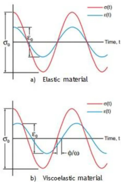
Viscoelastic materials have the particularity of possessing both viscous and elastic behaviour. Hooke’s law applies to elastic materials, where the stress is proportional to the strain and the Young’s modulus is defined as the stress to strain ratio. Figure 3 shows the distinct behaviour of viscoelastic and elastic stress-strain curves in time domain, where is the applied stress, the respective strain and ω the loading frequency (which is out-of-phase with strain by some angle . In fact, could be a measure of the materials damping capability. Considering an elastic material, the curves illustrate that all the energy stored during loading is returned when the load is removed, resulting in an in-phase stress-strain behaviour. Viscoelastic materials, on the other hand, exhibit a time dependent relationship between stress and strain, which means that the slope of the stress-strain plot depends on strain rate. For a viscoelastic material, the modulus is represented by a complex quantity with real and imaginary parts. For small stress excitation the viscoelastic materials reaction can be described by a linear viscoelastic behaviour, and due to the correspondence principle, the Young’s modulus and shear modulus can be treated as complex quantities, where the real part is known by Storage modulus and the imaginary part by Loss modulus, this latter defining the energy dissipative ability of the material [4].
Figure 3 – Elastic versus Viscoelastic material strain behaviour in time domain during cyclic stress loading: a) For an elastic material; b) For a viscoelastic material.
More precisely, the viscoelastic time dependency contrasts with common elastic materials, whose behaviour is not time dependent. The stiffness and strength of materials is frequently illustrated by a stress–strain curve as exemplify in Figure 4 for both viscoelastic and elastic-plastic materials. When the material is linearly elastic, its behaviour is typically a straight line with a slope proportional to the Young’s modulus. For a sufficiently large stress, the
elastic material exhibits a threshold stress, the yield stress . However, in the viscoelastic
curve both time and strain increase together. Thus, viscoelastic materials strain-stress analysis reveal the typical behaviour shown with more detail in Figure 5. For such type of materials, energy is stored during the loading cycle, whereas during the unloading phase the energy recovery follows the pattern shown in Figure 5, where the shaded region is a measure of the energy lost due to heat transfer mechanisms during deformation. Moreover, it is well known that the area beneath a stress-strain curve is the energy per unit volume. Therefore, when the load is removed, viscoelastic materials exhibit a time delay in returning the material to its original shape, which comes from the energy loss mechanisms.
Figure 4 - Stress–strain plots comparison for viscoelastic and elastic-plastic materials under constant strain rate [20].
When this type of material is submitted to a load condition, part of the deformation induced by shear stressing has an elastic nature and will return to zero when the force is removed. The other part of deformation will not return to zero when the force is removed because the elastic displacement remains constant, whereas the sliding displacement continues, with tendency to increase. This is the description for viscoelastic capacity to both store and
dissipate mechanical energy [17, 18]. Furthermore, the viscoelastic response depends on all
past states of stress and strain, which confers a “memory” capacity according to all previous stress conditions applied to the material [19].
Figure 5 – Typical stress-strain behaviour in viscoelastic materials.
Commonly, a creep recovery test is used to characterize such memory capacity from the dynamic response. Figure 6 illustrates a typical viscoelastic curve response resulting from a creep-recovery test. The dynamic response is said to exhibit both an instantaneous elasticity effect and creep characteristics; therefore, as it can be seen, this behaviour is not fully described by either considering the elasticity or viscosity theory sole effect, but from the combination of features from each of these theories.
Figure 6 - Typical viscoelastic curve response resulting from a creep-recovery test [20].
Analytically, the relationship between shear stress, elastic stress and viscous stress can be described in terms of a complex number “ i ” (i= ) . Thereby, the real part of a complex modulus represents the elastic portion and the imaginary part represents the viscous portion of the material response. The elasticity and viscosity components of viscoelastic materials are
often described by a relation using Young’s modulus E and Poisson’s ratio of the material.
These relations count both longitudinal and transverse response so that E and could be calculated as described in equations (2.1) and (2.2) [20, 21]:
(2.1) (2.2)
Where G is the shear modulus and K is the bulk modulus. However, for a complete characterization of the viscoelastic behaviour it is more convenient to use the complex shear
modulus and complex bulk modulus rather than E and , which in turn can be obtained
by using relations valid for homogeneous, isotropic and linear solid viscoelastic materials. Thus, a complete description of the viscoelastic behaviour can be obtained from equations (2.3) and (2.4). Similarly, Poisson's ratio and Young’s modulus are complex parameters given
by equations (2.5) and (2.6). Thus, in the following equations is the storage shear modulus,
is the loss shear modulus, is the storage bulk modulus, is the loss bulk modulus,
dynamic ration, is the Poisson’s loss ratio, is the storage Young’s modulus and is the
loss Young’s modulus.
(2.3)
(2.4)
(2.5)
(2.6)
Energy storage and dissipation cannot be negative, so both real and imaginary parts of a complex modulus have to be non-negative. Regarding the Poisson’s ratio in viscoelastic materials, many studies account for the difference between Poisson’s ratios in creep and in relaxation and its time dependence, concluding that the difference is minor unless there is a large relaxation strength. In this case, Poisson’s ratio is assumed constant in time for low-density materials, especially honeycombs and foams [23]. This will be the assumption for the definition of the cork properties in the numerical model described in this work. Furthermore,
given and , it is possible to determine both the complex shear modulus( ) and complex
bulk modulus ( ) by using the following expressions [22, 24] :
(2.7)
(2.8)
The most widespread theory used to model polymers (including FRPs) is based in theory of linear viscoelasticity which describes that, at any given time and for small strain, there is a linear relationship between stress and strain. Any linear viscoelastic material behaviour may be represented by a hereditary approach based on the Boltzmann superposition principle, which will be analysed ahead in this work.
Temperature effects on viscoelastic behaviour
Polymeric materials widely used as damping treatments are more sensitive to temperature than general metals, plastics or composite materials. Viscoelastic properties, such as the complex modulus, present three main temperature regions of interest, namely the glassy
region, transition region, and rubbery region [16, 25, 26]. Low temperatures are represented by the glassy region where the storage modulus is generally much higher than that for the transition or rubbery regions. This region can be defined by different temperature values for different materials depending on the viscoelastic composition. Figure 7 illustrates the behaviour of the complex shear modulus and loss factor in the different temperature regions. For the glassy region, loss factor is characterized by small values due to the high storage modulus dimension. Thus, in this region, the viscoelastic material presents high stiffness being unable to deform at the same magnitude (per unit load) as it would operate in the transition or rubbery regions (where the material is softer). Hence, for high operation temperatures, viscoelastic materials present low storage moduli and, consequently, low stiffness. That low value is typical of the rubbery region where the loss factor is equally smaller due to the increasing structural breakdown of material as the temperature is increased being the viscoelastic material easily deformable. Devices as isolators or tuned mass dampers are the most appropriate to be used in this region of temperature because the shear modulus is nearly constant.
Figure 7 - Temperature effects on complex modulus and loss factor.
In the context of the present work, the most important region relies between the glassy and rubbery regions, known as transition region. Due to the fact that the maximum loss factor value is reached in this region, applications with viscoelastic materials for damping purposes generally should be used within the transition temperature range. Here, frictional molecular effects result in the increase of the mechanical damping characteristic of viscoelastic materials. Therefore, knowing the operating temperature range during the design phase of a host structure to which a viscoelastic damping treatment will be applied will be determinant
Frequency effects on viscoelastic behaviour
As for the temperature effect described in the last section, frequency variation also has a significant effect in the complex modulus properties of a viscoelastic material. As Figure 8 shows, frequency has an inverse relationship to complex shear modulus when compared with temperature, since the storage modulus and the loss factor are small at low frequencies. This is due to the low cyclic strain rates within the viscoelastic layer. As the frequency increases, the material converges to the transition region where the loss factor reaches a maximum value. With a further frequency increase, the storage modulus raises but loss factor decreases. As it happens with the temperature dependence, the transition region is the typical operating frequency range for loss factor maximization [27-29].
Figure 8 - Frequency effects on complex modulus and loss factor
2.2.3 Linear viscoelasticity response: Mathematical models
Viscoelastic behaviour can be represented using mathematical models based on spring and dashpot elements corresponding to the elastic and viscous responses, respectively (as illustrated in Figure 9). Aiming at simplifying the analysis of this type of material, linear theory models are the most successful widespread methods, supporting extrapolation or interpolation of experimental data, reducing complex approximations and time-consuming
calculations. The description of a viscoelastic model can be resumed by considering the elastic and viscous terms formulated in equations (2.9) and (2.10), respectively:
(2.9)
(2.10)
Figure 9 - Mathematical models for viscoelastic response
The elastic term is modelled as springs and the other term, the viscous component, as
dashpots. E represents the Young’s modulus,
is the viscosity of the material,
thecorrespondent strain and
is the strain rate. Instantaneous inherent deformations of the
material are modelled like a spring response with a magnitude related to the fraction of mechanical energy stored reversibly as strain energy. The entropic uncoiling process is fluid like some cases in Nature, and can be modelled by a Newtonian dashpot. The main models used to describe the viscoelasticity in materials are listed below.The Maxwell model
This model consists of an elastic spring in series with a viscous dashpot. When the ends are pulled apart with a certain force, the stress on each element is the same and equal to the imposed stress, as described in equation (2.11).
(2.11)
The total strain rate is equal to the sum of the spring rate and the dashpot rate, and the absolute total strain can be divided in the strain in each element, as described in equation
(2.12). In a simplistic way, Maxwell model is usually applied in cases with small deformations. Instead, large deformations should include some geometrical non-linearity. The model characterizes a general material response under a constant strain, where the stresses gradually relax, and under a constant stress, where the strain can be divided in both elastic and viscous components. The elastic response occurs instantaneously, corresponding to the spring elastic contribution, and relaxes immediately upon stress release assumed by the
viscous component which grows with time as long as the stress is applied.
(2.12)
By differentiating the strain equation and writing the spring and dashpot strain rates in terms of the stress, the following equations can be obtained:
(2.13)
(2.14)
Where k is the elasticity constant of the spring, is the stress and is the material’s viscosity. In Maxwell model, stress decays exponentially with time, a well-known phenomenon for most polymers; however, its creep response prediction is difficult and limited. Additionally, at creep or even at constant-stress conditions, this model shows that strain will increase linearly with time, assuming that for most polymers cases the strain rate decreases with time [21, 30].
The Kelvin-Voigt model
This model can be represented by a Newtonian damper and a purely elastic spring connected in parallel. Thus, this model can be viewed as a mixture of a linearized elastic solid and a linearly viscous fluid that co-exist, where the constitutive relation is a sum of the two terms. Hence, the total stress will be the sum of the stress in each component [31]:
(2.15)
Another fact is that since the two components of the model are arranged in parallel, the strains in each component are the same:
(2.17)
For a situation with constant stress, Kelvin-Voigt model describes that a material deforms at a decreasing rate, approaching asymptotically the steady-state strain. Although the model does not accurately describe stress relaxation, dynamic response is characterized by a gradual relaxation to its undeformed state [30]. However, only certain thermoplastics with low degree of cross-linking will deform accurately according to this model.
The standard linear solid or Zener model
This model offers more realistic representation of the material’s behaviour over the whole frequency range from creep and stress relaxation to dynamic modulus, dynamic loss factor, rate effects and impact loading. It uses a linear combination of springs and dashpots, which basically consists in adding a spring in parallel with the Maxwell model. Since the Maxwell model does not describe creep or recovery, and the Kelvin–Voigt model does not describe stress relaxation, the standard linear solid is the simplest model capable to predict both [32]. Taking into consideration changes in stress and strain at the same time, the general viscoelastic behaviour in equilibrium can be summarized as:
(2.18)
(2.19)
Where is the true stress, is the true strain, the spring Young’s modulus in series with
the dashpot and the parallel spring Young’s modulus. Therefore, at stress relaxation, the
The Boltzmann superposition integral
Remembering that in the dynamic response of a viscoelastic material, internal stresses are a function not only of the instantaneous deformation but also depend on the strain past history. Therefore, the most recent past history has more influence fostering the linear viscoelasticity as the simplest way to model the response of such materials. With the Boltzmann superposition principle, the current stress is determined by the superposition of the responses, using the strain increment. Let’s consider the function representative of some
shear strain acting on a viscoelastic material and as the shear stress (which represents
the effect resulting from the shear strain). A variation in shear strain occurring at time will
influence the effect some time later, which can be expressed by equation (2.20). Thus, for linear isotropic viscoelasticity response, the basic hereditary integral formulation is given by equation (2.21):
(2.20) (2.21)
(2.22)
(2.23)
Being and the mechanical deviatoric and volumetric strains, K is the bulk modulus and G is the shear modulus, functions of the reduced time . This reduced time parameter is related to the actual time through the integral differential equation described in equations (2.22) and
(2.23). In equation (2.20), represents a relaxation function or relaxation modulus,
which is a function of the time delay between cause and effect, known as independent of the strain amplitude, which represents the “fading memory” mentioned before. For equations (2.22) and (2.23), is the temperature and is the shift function (Williams-Landel-Ferry [WLF] equation is the most used shift equation), highly related with the temperature
dependence of viscoelastic materials. The FEM software used in this work allows
the WLF equation to be used with any convenient temperature, for instance a reference
temperature. Therefore, note that if [33].
Regarding the vibration analysis of a composite material, general structural vibration can be measured using electronic sensors which convert vibration motion into electrical signals.
These signals can be considered either in time or frequency domains, depending on the type of information required for the analysis of results. Any time history signal can be transformed into the frequency domain using a Fourier transform, which requires some complex math. However, today's signal analysers, as the one used in this work’s experimental testing, race through it automatically in real-time conditions.
As it will be seen in chapter 4, the applied load used for the dynamic excitation of the composite beam under analysis in this work is small. Considering a shear test at small strain,
in which a time varying shear strain, , is applied to the material, the respective viscoelastic
response is the shear stress, , described as:
=
(2.24)
is the time dependent shear relaxation modulus, whose respective behaviour can be
illustrated by considering a relaxation test where a strain
is suddenly applied and held constant for a long time. For the initial condition t=0 and considering a fixed strain , then:
=
=
(since ) (2.25)Since the viscoelastic material model is long-term elastic, the response tends to a constant stress ( as t ) after a constant strain has been applied for a long time.
Resorting to the instantaneous shear modulus, , the shear relaxation modulus can
be written in a dimensionless form, as expressed in equation (2.26). Hence, the stress expression can be formulated like in equation (2.27):
(2.26)
=
(2.27)
2.2.4 Viscoelastic frequency dependence: numerical model
The dissipative part of the material dynamic response is defined by using the real and
a power law, given an experimental tabular input, or by a Prony series expression for the
shear and bulk relaxation moduli. In the solver, the viscoelastic material is defined
by a Prony series expansion of the dimensionless relaxation modulus [33]:
(2.28) (2.29)
Where X, , , , i=1,2,...,X are material constants.
During the numerical analysis, the solver will automatically perform the conversion between time and frequency domains. The time-dependent shear modulus can be obtained from the following expressions [33]: (2.30) (2.31) (2.32) (2.33)
Where is the storage shear modulus, is the loss shear modulus, is the storage bulk
modulus, is the loss bulk modulus, is the instantaneous shear modulus and is the instantaneous bulk modulus.
Since it was assumed that dissipative losses acting in the analysed specimens were mainly caused by internal damping (“viscous”) effects, the frequency domain was adopted for the analysis of the viscoelastic material, describing frequency-dependent material behaviour in small steady-state harmonic. Thus, it was assumed that the shear (deviatoric) and volumetric behaviours are independent in multiaxial stress states. Therefore, the tabular form was used
to model the dynamic motion of cork in software. This was defined by giving the
real and imaginary parts of and as functions of frequency in cycles per time, being
(2.34)
(2.35)
(2.36)
(2.37)
Where and are the long-term shear and bulk modulus determined from the elastic or
hyperelastic properties.
2.2.5 Vibration theory applied to viscoelastic materials
Structural mechanical vibrations can be subdivided according to the vibration sources or the systems’ constituents. On the other hand, vibration phenomena may occur in many areas of mechanical, civil and aerospace engineering.
The general response of a mechanical system, with n degrees of freedom, can be represented by the next equation:
In this equation, the terms [M], [C], [K] are the mass, damping and stiffness system matrices,
respectively; [F(t)] is the external load vector to be considered in the numerical model;
and are the acceleration, velocity and generalised displacement vectors, respectively. In a vibrating structure, the system’s parameters are used to create the mathematical model, in which the mass and stiffness can be derived as a function of the system’s geometry and material characteristics. In terms of finite element formulation, and considering a harmonic vibration, the equilibrium equations can be described by:
(2.38)
The harmonic response assumes the form:
(2.40)
Where represents all eigenvectors of each vibration mode, the frequency value and t the time domain. Now, by replacing equation (2.40) in (2.39) we will get:
(2.41)
Considering vector [F(t)] = 0, and noting that cannot be equal to zero, equation (2.41)
assumes the form:
(2.42)
In equation (2.42), is and represents the eigenvalues of the system. So if
=
, thesolution of this expression corresponds to a conventional eigenvalue problem and has a correspondent eigenvector that represents the system modes of vibration [12]. Thus, for a
general damping system, the damped natural frequencies ( ) are given by:
(2.43)
Where and are the undamped natural frequency and the damping ratio, respectively.
From the numerical model using a conventional finite element code it is possible to determine the system’s mass and stiffness matrices. On the other hand, damping can be simulated from the mathematical theory concerning the Rayleigh damping model, where the energy dissipation of the system can be expressed by a damping matrix [C] with symmetric coefficients. In this model, the symmetric damping matrix [C] is a linear combination of the mass and stiffness matrixes of the system. Therefore it can be defined as:
In equation (2.44), α is the mass proportional damping factor and β is the stiffness proportional damping factor. Both have an important role in modelling damping, where α and β are the attributes of the lower and higher natural frequencies, respectively. In equation (2.45) is the natural frequency obtained through modal analysis and ξi the respective
modal damping ratio. Pointing out that the structural component developed in this work will typically operate at relative low frequencies (for example, for space applications or low frequency noise control) it is assumed that β‹‹1, resulting in higher structural dependency of α value. Therefore, relating equations (2.42), (2.43) and (2.45) allows concluding that the mass proportional damping factor and the stiffness proportional damping factor can assume the form:
α
(2.46)
Thus,
In the abovementioned equations, for a given ith vibration mode, is the damped natural frequency, the damping ratio and the loss factor. In a dynamic analysis relying upon a finite element model, damping is related with these and parameters, which directly affect the damping ratio, and consequently, the loss factor. Given that, for numerical purposes, the mass coefficient (α) is an input and should be based on experimental data obtained for the particular specimen geometry and types of materials considered in this analysis.The elastic and viscous stresses are related to the material properties through the storage modulus, which represents a ratio of stress to strain (if elastic stresses are considered) or loss modulus (in the case of considering viscous stresses) [4].
(2.45) α α (2.47) α (2.48) α (2.49)
2.3 Damping on Sandwich structures with constrained layer
Due to the importance of layered composites in a wide range of industrial and aerospace applications and its increasing investment prospective, the vibration control of layered composites has been an area of fundamental research over the past fifty years. The sandwich structure solution depends on variable parameters, such as the skin, core layers and adhesive attachment in the interface regions [34]. The separation of the outer faces by the core increases the moment of inertia of the panel with little increase in weight, producing an efficient structure for resisting bending and buckling loads. Normally, sandwich structures are fabricated by attaching two thin stiff skins as laminate covers, a lightweight core with variable thickness to separate those skins and carry the loads between them, which in turn are joined by an adhesive element capable of transmitting shear and axial loads to and from the core [35]. Figure 10 illustrates some of the types of cores used in sandwich composite structures.
(a) Foam (b) Honeycomb (c) Corrugated
Figure 10- Types of cores used in sandwich components [34].
Ross, Kerwin and Ungar (RKU) [35] made a pioneering work consisting in modelling a three-layer sandwich beam to predict damping in plates with embedded damping three-layer. The first theoretical approach was presented by Kerwin regarding damped thin structures with a constrained viscoelastic layer. This author concluded that the energy dissipation mechanism in the constrained core is attributed to its shear motion, and as such the viscoelastic core was represented by a complex modulus. Furthermore, the sandwich based upon Euler-Bernoulli beam theory, known as Mead and Markus model, disregards the longitudinal and rotational inertia from the outer layers, but it only includes transverse inertia and shear effects in the central core layer (i.e., longitudinal momentum, bending and extensional stresses are ignored in the core). Rao and Nakra included these same effects in their equation of motion using the energy method [36-38]. These are the most widespread basic theories and models for a layered sandwich beam with a viscoelastic material core, although most of them neglect the effect of shearing in the skins.
![Table 3 - Rao correction factors for shear parameter in RKU equations [16].](https://thumb-eu.123doks.com/thumbv2/123dok_br/18206896.876410/48.892.167.682.114.331/table-rao-correction-factors-shear-parameter-rku-equations.webp)
![Figure 12 - Numerical prediction of the loss factor based on the real part of the response spectrum [40]](https://thumb-eu.123doks.com/thumbv2/123dok_br/18206896.876410/49.892.256.650.127.446/figure-numerical-prediction-loss-factor-based-response-spectrum.webp)
![Figure 16 - Example of cork application in the propulsion system of Space Shuttle [45]](https://thumb-eu.123doks.com/thumbv2/123dok_br/18206896.876410/53.892.178.757.102.536/figure-example-cork-application-propulsion-space-shuttle.webp)