!"#"$ % & '( )
* & + ,- ) . / *+). #$01$ 2$3 4 ( . ( 5
!"#"$ % & '( )
!
"
This work aims at developing a genetic algorithm (GA) to pursue the optimization of hybrid laminated composite structures. Fiber orientation (predefined ply angles), material (glass-epoxy or carbon-epoxy layer) and total number of plies are considered as design variables. The GA is chosen as an optimization tool because of its ability to deal with non-convex, multimodal and discrete optimization problems, of which the design of laminated composites is an example. First, the developed algorithm is detailed explained and validated by comparing its results to other obtained from the literature. The results of this study show that the developed algorithm converges faster. Then, the maximum stress, Tsai-Wu and Puck (PFC) failure criteria are used as constraint in the optimization process and the results yielded by them are compared and discussed. It was found that each failure criterion yielded a different optimal design.
Keywords: hybrid laminated composites, optimization, genetic algorithm
Introduction
1
Composite material is usually understood as the combination of two or more materials on a macroscopic scale to form a useful third material (Jones, 1999). The advantage of composite materials is that, if correctly designed, they display the best qualities of their constituents and often some qualities that neither constituent possesses (Jones, 1999).
A laminated composite is usually tailored according to the designer’s needs by choosing the thickness, number and orientation of the laminae. To achieve the best results, optimization techniques have been developed, and one such technique, the genetic algorithm (GA), has been widely used to determine the optimal design of composite structures (Le Riche and Haftka, 1993; Nagendra et al., 1994; Todoroki and Haftka, 1998; Liu et al., 2000). Known advantages of the use of GAs include the following: (i) they do not require gradient information and can be applied to problems where the gradient is hard to obtain or simply does not exist; (ii) if correctly tuned, they do not get stuck in local minima; (iii) they can be applied to non-smooth or discontinuous functions; and (iv) they furnish a set of optimal solutions instead of a single one, thus giving the designer a set of options. On the other hand, the use of GAs has a number of known drawbacks, which include the following: (i) they require the tuning of many parameters by trial and error to maximize efficiency; (ii) the a priori estimation of their performance is an open mathematical problem; and (iii) an extremely large number of evaluations of the objective function are required to achieve optimization, which can make the use of GAs nonviable depending on the computational cost of each evaluation.
In the design of laminated composites, the ply thicknesses are often predetermined and the ply orientations are usually restricted to a small set of angles due to manufacturing limitations and/or limited availability of experimental data. This leads to problems of discrete or stacking-sequence optimization. Many objective functions have been introduced, such as the buckling load (Le Riche and Haftka, 1993; Liu et al., 2000) (to be maximized), the stiffness in one direction (to be maximized), and the strength (Groenwold and Haftka, 2006) (to be maximized), as well as the cost or weight (Nagendar et al., 1994; Seresta et al., 2007; Le Riche and Haftka, 1995; Naik, Gopalarishnan and Ganguli, 2008) (to be minimized). A
Paper accepted April, 2009. Technical Editor: Nestor A. Zouain Pereira
popular approach used by many researchers to maximize the strength consists of minimizing the failure factor of a failure criterion, such as the maximum strain/stress, Tsai-Hill, Hoffman or Tsai-Wu criteria. However, the Tsai-Wu failure criterion contains linear and quadratic terms, and therefore the resulting designs become dependent on the load level. Groenwold and Haftka (2006) suggested that for this criterion the safety factor (i.e., the largest multiplicative factor that can be applied to the actual loads without violating the failure criterion) can be maximized instead of minimizing the failure factor and the resulting design becomes independent of the load level.
In addition to the failure criterion, other restrictions are usually involved in the optimal design of laminated composites. Examples of such restrictions in the literature include upper and bound limits for the design variables, laminate symmetry and balance, and a maximum number of contiguous plies (this last restriction is often used to prevent matrix cracking). Liu et al. (2000) applied and compared repair strategies using a maximum number of contiguous plies and showed that the Baldwinian repair strategy drastically reduces the computational cost of constrained optimization (the cost of the GA, measured by the number of function evaluations necessary to achieve the optimization, is reduced by one or two orders of magnitude). The first ply failure constraint is often handled by a penalty approach (Le Riche and Haftka, 1993; Nagendra et al., 1994).
When the optimization problem involves continuous and discrete variables (a mixed-variable problem), the representation of the variables in a single string in the GA increases the dimension of the design variables space (since one real variable is transformed into many integer ones). To overcome this problem, decomposition approaches have been introduced (Antonio, 2001). These often involve decomposition at local and global levels: at the local level the best stacking sequence is determined for a given geometry, and at the global level new geometries are generated based on the result furnished by the local level. Such an approach was adapted for optimal composite design by Murugan et al. (2007). Antonio (2006) introduced a hierarchical GA with age structure adapted for the optimal design of hybrid composite structures with multiple solutions. The algorithm he proposed addressed the optimal stacking sequence and material topology as a multimodal optimization problem. Antonio showed that the procedure for species control is effective because it allows multiple optimal solutions and guarantees subpopulation diversity.
With regard to failure criteria, Naik, Gopalakrishnan and Ganguli (2008) used a GA to determine the minimum weight design of laminated composites under restrictions associated with the maximum stress (MS) and Tsai-Wu (TW) criteria as well as a failure-mechanism-based criterion.
One of the main criticisms of many studies related to optimal composite design is the use of failure criteria based on the von Mises or Hill yield criteria, which are more suitable for ductile materials (Puck and Schürmann, 1998). In fact, as the failure behavior of composite parts is similar to that of brittle material, it would be more appropriate to use criteria suited to materials that exhibit brittle fractures, such as Mohr’s criterion. A suitable criterion for composites that takes this fracture behavior into account is, for instance, the Puck failure criterion (PFC) (Puck, 1996; Puck and Schürmann, 1998).
This work develops a genetic algorithm to pursue the optimization of hybrid laminated composite structures. Fiber orientation (predefined ply angles), material (glass-epoxy or carbon-epoxy layer) and total number of plies are considered as design variables. First, the developed algorithm is validated by comparing their results to other found in the literature (Girard, 2006). Then, three different failure criteria, the MS, TW and the PFC, are used as constraint in the optimization and their results are compared. The paper is organized as follows. In Section ‘Genetic Algorithm’ the chromosome representation, the genetic operators and the constraint handling are described. Section ‘Failure Criteria’ presents a brief review of the failure criteria used in this work. The problem statements and numerical results are shown in Section ‘Numerical Results’. Finally, Section ‘Conclusions’ reports the main conclusions that were drawn.
Nomenclature
C1 = stack orientation chromossome
C2 = stack material chromossome
CE = carbon-epoxy ply
Dij = coeficient of the laminate bending stiffness matrix, Nm
Ei = Young’s modulus of the ply in direction i, Pa
Efi = Young’s modulus of the fiber in direction i, Pa
FE = number of function evaluations
FF = fiber failure mode
Fi = parameter of Tsai-Wu failure criterion, 1/Pa
Fij = parameter of Tsai-Wu failure criterion,1/Pa2
fw = weakening factor for PFC, dimensionless
G = shear modulus, Pa
GE = glass-epoxy ply
IFF = inter-fiber failure mode
lp = plate length, m
m = number of half waves of a buckling mode in direction x
m.u. = monetary unit
MS = maximum stress failure criterion
mσf = mean stress-magnification factor for fibers in the x2 direction, due to the difference between the transverse modulus of the fibers and the matrix (parameter of PFC), dimensionless
n = number of half waves of a buckling mode in direction y,
total number of stacks of a laminate N = in plane load, N/m
PFC = Puck failure criterion ( )
||
p⊥+ = slope of the (σn,τnl) fracture envelope for σn ≥ 0
(parameter of PFC), dimensionless ( )
||
p⊥− = slope of the (σn,τnl) fracture envelope for σn ≤ 0
(parameter of PFC), dimensionless
( )
p⊥⊥− = slope of the (σn,τnt) fracture envelope for σn ≤ 0 (parameter of PFC), dimensionless
A
R⊥⊥ = fracture resistance of the action plane against its
fracture due to transverse/transverse shear stressing (parameter of PFC), Pa
S = fiber failure (FF) factor of PFC, dimensionless
S12 = shear lamina strength, Pa
SD = standard deviation
TW = Tsai-Wu failure criterion
wp = plate width, m
X = lamina strength parallel to the fiber direction, Pa
Y = lamina strength normal to the fiber direction, Pa
Greek Symbols
τ = shear stress, Pa
εi = normal strain in direction i, dimensionless
εiC = compressive failure strain in direction i, dimensionless
εiT = tensile failure strain in direction i, dimensionless
γ = shear strain, dimensionless
λ = buckling load factor, dimensioless
ν = Poisson’s ratio, dimensionless
νf12 = Poisson's ratio of the fiber, dimensionless
θfp = angle of the fracture plane, deg.
θk = ply orientations, deg.
ρ = mass density, kg/m3
σ = normal stress, Pa
Subscripts
1 relative to material coordinate direction
2 relative to material coordinate direction
3 relative to material coordinate direction
C relative to compression
cr relative to critical buckling load
fp relative to failure plane
k relative to fiber orientation min relative to minimum buckling factor
n relative to normal to the failure plane
p relative to plate
t relative to tangential to the failure plane
T relative to tensile
x relative to x coordinate
Genetic Algorithm
Genetic algorithms loosely parallel biological evolution and were originally inspired by Darwin’s theory of natural selection. The specific mechanics of genetic algorithms often use the language of microbiology, and their implementation frequently mimics genetic operations (Arora, 2004). A GA generally involves genetic operators (such as crossover and mutation) and selection operators intended to improve an initial random population. Selection usually involves a fitness function characterizing the quality of an individual in terms of the objective function and the other elements of the actual populations. Thus, a GA usually starts with the generation of a random initial population and iterates by generating a sequence of populations from the initial one. At each step the genetic operators are applied to generate new individuals. The fitness of each available individual is computed and the whole population is ranked according to increasing fitness. A subpopulation is then selected to form a new population. Many selection methods may be found in the literature. In this work, tournament selection is applied (see Schmitt, 2001). At this point, the algorithm may repeat the process or, before that, a local search may be pursued, which is the case of this paper. Two local search methods are employed, named as: Neighborhood Search and Material Grouping (Girard, 2006). Then, all the procedure is repeated until a stopping condition is satisfied.
The genetic operators employed in this work are crossover, mutation, gene swap, stack-deletion and stack-addition. In the following, the constraint handling, chromosome coding and the genetic operators are shown in detail.
Constraint Handling
In GAs, the most common ways of handling constraints are data structure, repair strategies and penalty functions (Puzzi and Carpentieri, 2008). The symmetry and balance of the laminate are handled by using the data structure strategy, which consists of coding only half of the laminate and considering that each stack of the laminate is formed by two laminae with the same orientation, but opposite signs (for instance, ±45o).
A double-multiplicative dynamic penalty approach (Puzzi and Carpentieri, 2008) is used here to take into account the failure criteria. This approach leads to a penalty term being added to the objective function: this supplementary term has a multiplicative form and involves autonormalization. It is written as
( )
( )
1
1
m j
j j
ˆg q Q
P ,q
b Q
=
+
= +
∏
xx , (1)
where m is the number of constraints, x is the vector of the design variables, ˆg ( )j x is the constraint violation, bj is a normalization
parameter, q is the current generation number and Q is the total number of generations. The main advantage of this approach is that the penalization parameters do not need to be tuned.
Chromosome Representation
The classical binary representation is not used here; instead, the allowed angle values represent the genes of the chromosomes (i.e., [02 ±45 902]). In our numerical examples, we consider the optimization of a hybrid laminated composite. In this case, each individual in the population is represented by two chromosomes: the first describes the angle of orientation of the layers, and the second the layers materials, Table 1 details this approach.
Table 1. Chromosome representation.
Stack Orientation Chromosome (C1)
Empty Stack 02 ±45 902
0 1 2 3
Stack Material Chromosome (C2)
Empty Stack Carbon-Epoxy (CE) Glass-Epoxy (GE)
0 1 2
The orientation angle and material of each ply are coded in the chromosomes of each individual. One example of chromosome decoding is shown in Fig. 1.
Figure 1. Example of chromosome decoding.
Crossover
Crossover is the basic genetic operator. It involves combining the information from two parents to create one or two new individuals. The X1-thin crossover operator is presented in Le Riche and Haftka (1993) and used here. In Le Riche and Haftka (1993) several crossover methods are described and compared. The X1-thin is a one-point crossover strategy that restricts the location of the breakpoint to the full part of the thinner parent laminate and generates two new individuals, as shown in Fig. 2.
Figure 2. Example of crossover operation.
Mutation
The mutation operator must be applied in the GA to guarantee gene diversity so that the algorithm does not get stuck in local minima (Schmitt, 2001). In the present work, this operator is based on randomly changing the value of a gene in the chromosome. Thus, the algorithm chooses an individual of the population and then, also randomly chooses a gene to be mutated. As the work is dealing with hybrid laminated composites, the mutation is applied to the angle as well as to the material chromosome. Figure 3 exemplifies both mutations.
Gene-Swap
The gene-swap operator selects two genes randomly from a laminate and then swaps them. It was introduced by Le Riche and Haftka (1995), who showed that the permutation operator (Le Riche and Haftka, 1995), which was used before the gene-swap operator was introduced, shuffles the digits too much and that the gene-swap operator is more efficient. The same authors showed that this operator is quite effective when the problem deals with buckling load, because when an individual has a good pool of genes, the gene-swap helps to reorganize them, possibly resulting in a better design than when the mutation is applied. One example of gene-swap for hybrid laminate chromosome is given in Fig. 4.
Figure 4. Example of gene-swap operator.
In the example of the hybrid laminated composite referred to above, the crossover points of the two chromosomes for each individual are the same. In addition, when the gene-swap is applied, both orientation and material are swapped.
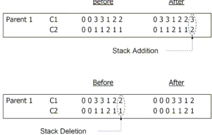
Stack Addition-Deletion
We introduce two supplementary operators. The first one adds and the second deletes a lamina of the composite part under design. The first operator tends to force the laminate to satisfy the first ply failure constraint, while the second one tends to reduce the weight of the laminate, thus forcing the laminate to satisfy the criterion of minimum weight. An example of this operator is in Fig. 5.
Figure 5. Example of stack addition-deletion operators.
Both operators always act on the lamina closest to the mid-surface of the laminate, since it has the weakest effect on the bending properties of the structure. This feature may be important when buckling is involved, since buckling is highly dependent on the bending properties of the laminate. It is more convenient to delete the lamina with the weakest influence on the bending
properties, since it is observed in practice that the algorithm rapidly converges to the best design for the most external laminae.
Local Search
Local search may be employed in the GA in order to accelerate the convergence of the algorithm. As already mentioned, two local search methods are used: Neighborhood Search and Material Grouping.
The Neighborhood Search is based on making small changes in the genes of the chromosome that represents the orientations. One individual is chosen among the best designs of the population (i.e., among the five best individuals). Then, one of its genes is randomly chosen and the other allowable values that this gene may have are tested. Finally, the best design is chosen to remain in the population (i.e., the best design among individual, test 1 and test 2, as shown in Fig. 6).
Figure 6. Example of Neighborhood Search operator.
In the practice of optimizing laminated composites, it has been noted that usually the different material laminas are grouped together at the optimal design (Girard, 2006). Thus, the Material Grouping method consists in grouping the material laminas of a chromosome. First, one individual is chosen among the best ones of the population. Then, the genes with the same material are grouped and the new design is tested. If such design is better than the original one, it is kept in the population. The Material Grouping operation is depicted in Fig. 7.
Figure 7. Example of Material Grouping operator.
Failure Criteria
Figure 8. Principal material coordinates of a typical unidirectional lamina.
Maximum Stress Failure Criterion (MS)
According to the maximum stress theory, failure is predicted when a maximum stress in the principal material coordinates exceeds the respective strength. That is,
1 XT or 2 YT
σ ≥ σ ≥ (for tensile stresses)
1 XC or 2 YC
σ ≤ − σ ≤ − (for compressive stresses)
12 S12
τ ≥ (for shearing stresses) (2)
whereσ1 and σ2are the normal stresses in the directions 1 and 2,
respectively; τ12 is the shear stress in the elastic symmetry plane 1-2; XT and XC are the tensile and compressive strengths parallel to the
fiber direction, respectively; YT and YC are the tensile and compressive
strengths normal to the fiber direction, respectively; and S12 is the
shear strength. Note that XT, XC,YT, YCand S12 are positive quantities.
Tsai-Wu Failure Criterion (TW)
The Tsai-Wu criterion, formulated to predict failure of orthotropic materials, is derived from the von Mises yield criterion. It states that the lamina fails when the following condition is satisfied
2 2 2
11 1 2 12 1 2 22 2 21 12 1 1 2 2 1
Fσ + Fσ σ +F σ +Fτ +Fσ +Fσ ≥ (3)
where Fi and Fij are parameters that are a function of the strength
properties XT, XC, YT , YC and S12 (see, for instance, Jones, 1999).
Puck Failure Criterion (PFC)
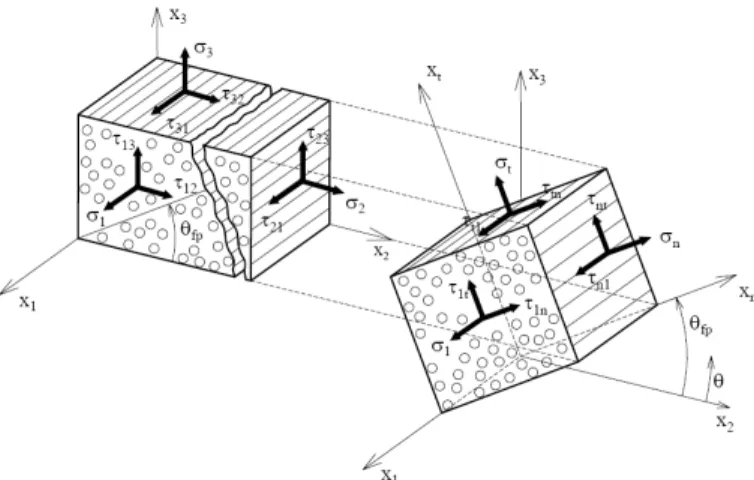
In this section, only the main features of the PFC are presented. The entire derivation can be found in Puck (1996) and Puck and Schürmann (1998). The PFC follows Mohr’s hypothesis that fracture is caused exclusively by the stresses that act on the fracture plane. It involves two main failure modes: Fiber Failure (FF) and the Inter-Fiber Failure (IFF) (Puck and Schürmann, 1998).
FF is based on the assumption that fiber failure under multiaxial stresses occurs at the same threshold level at which failure occurs for uniaxial stresses.
Instead of dealing with the principal material coordinates (axes 1-2-3), IFF equations are derived based on the axes corresponding to the failure plane. These axes are shown in Fig. 9, where θfp
represents the angle at which failure occurs. The PFC therefore provides not only a failure factor, but also the inclination of the plane where failure will probably take place, thus allowing a much better assessment of the consequences of IFF in the laminate.
Figure 9. Transformation from the 1-2-3 axes to the axes corresponding to the failure plane (σn, τnt, τn1).
IFF is subdivided into three failure modes, as described in Puck and Schürmann (1998), which are referred to as A, B and C. Mode A occurs when the lamina is subjected to tensile transverse stress, whereas modes B and C correspond to compressive transverse stress. The classification is based on the idea that a tensile stress σn > 0 promotes fracture, while a compressive stress σn < 0 impedes shear
fracture. For σn < 0, the shear stresses τnt and τn1 (or just one of them)
have to face an additional fracture resistance, which increases with |σn|, analogously to an internal friction (Puck and Schürmann, 1998).
The distinction between modes B and C is based on their failure angles, which are 0º for mode B and a different value for mode C. In addition, failure mode C is considered more severe, since it produces oblique cracks and may lead to serious delamination.
The equations for the PFC are summarized in Table 2, where we also introduce a weakening factorfw, which decreases the strength
of the laminate due to high stress in the fiber direction. According to Puck and Schürmann (1998), fw is given by
(
0.9 ( ))
n w E FF
f = f (4)
where fE( FF ) is the failure effort for FF in the lamina, and n, in this
Table 2. Equations for the PFC (Puck and Schürmann, 1998).
Type of failure Failure Mode Failure Condition (fE(FF)or fE(IFF)) Condition for validity
Fiber Failure (FF) Tensile 1
1
=
T
S
ε ifS≥0
2 1 1 12
1 σ
ε mσ
E v S f f +
= Compressive (10 )2 1
21 1 = + − γ εC S
if S<0
Inter Fiber Failure (IFF) Mode A 1 1
21 2 ) ( || 2 2 2 21 ) ( || 2 21
21 + + =
− + + ⊥ + ⊥ w T T f S p Y S Y p S σ σ τ 0 2≥ σ
Mode B 1
(
)
12 ) ( || 2 2 ) ( || 2 21 21 = + + + − ⊥ −
⊥ p fw
p
S τ σ σ
2 2
21 21
0 and 0 σ σ
τ τ⊥⊥
< ≤ ≤ A
c
R
Mode C
(
)
1) ( 1 2 2 2 2 2 21 ) (
21 + =
− + + − ⊥⊥ w C C f Y Y S p σ σ
τ 21 21
2
2
0 and 0 Ac R τ τ σ
σ ⊥⊥
< ≤ ≤
Definitions
2
( ) 21
2 21 2
||
2 0
of ( , ) curve, 0 d
p
d σ
τ σ τ σ
σ + ⊥ = = − ≥ 2
( ) 21
2 21 2
||
2 0
of ( , ) curve, 0 d
p
d σ
τ σ τ σ
σ − ⊥ = = − ≤
Parameter relationships
(
)
− + = + = − ⊥ − ⊥ − ⊥⊥
⊥⊥ 1 2 1
2 1 2 21 ) ( || ) ( || 21 ) ( S Y p p S p Y
RA C C
21 ) ( || ) ( S R p p A ⊥⊥ − ⊥ − ⊥⊥=
(
)
( ) 21c S21 1 2pτ −
⊥⊥
= +
Numerical Results
Example 1: Material Cost Minimization Under Buckling and Weight Constraints
In this example, the material cost minimization of a hybrid laminated composite plate is described. Two types of layers are considered: carbon-epoxy (CE) and glass-epoxy (GE). The former is lighter and stronger, while the latter has a cost advantage as the price per square meter of this laminate is about 8 times less. The laminated is subjected to symmetry and balance constraints as well as a maximum weight and a minimum buckling load factor. The allowable orientation angle values are 02,±45 and 902 degrees. Thus, the optimization problem reads as follows:
Find:
{
θk, mat ,k n}
,θk∈{
0 , 45, 902 ± 2}
,matk∈{
GE, CE}
, k = 1 to n (5)Minimize Material cost
Subject to: Minimum buckling load factor λcr ≥λmin
Maximum weight: 85 N
where θk is the orientation of each stack of the laminate and n the
total number of stacks. As already mentioned, each stack is composed of two layers to guarantee balance. In this problem, each CE and GE layer is also assumed to cost 1 and 8 monetary units (m.u.), respectively.
The plate is rectangular, simply supported and subjected to compressive in-plane loads per unit length Nx and Ny, as shown in
Fig. 10. Each layer is 0.127 mm thick, and the length and width of the plate are 0.92 m and 0.75 m, respectively. The classical lamination theory and the linear buckling analysis (Jones, 1999) is used. The buckling load factor λcr represents the failure buckling
load divided by the applied load, and is calculated as (see Gürdal, Haftka and Hajela, 1999),
(
)
4 2 2 4
2
11 12 66 22
2 2
2 2
p p p p
cr m,n
x y
p p
m m n n
D D D D
l l w w
min m n N N l w π λ + + + = + (6)
where Dij are coefficients of the laminate bending stiffness matrix, m and n determine the amount of half waves in the x and y direction, respectively, lp is the plate length, wp is the plate width (Fig. 10).
Note that the Eq. 6 input requires positive values for compressive and negative values for tensile forces.
Figure 10. Laminated composite plate subjected to in-plane loads.
The elastic material properties of the CE layers are E1 = 138 GPa,
E2 = 9 GPa, G12 = 7.1 GPa, Poisson’s ratio ν12 = 0.30 and mass density ρ = 1605 kg/m3. The GE layer elastic material properties are
E1 = 43.4 GPa, E2 = 8.9 GPa, G12 = 4.55 GPa, Poisson’s ratio ν12 = 0.27 and mass density ρ = 1993 kg/m3.
The in-plane applied loads are fixed compressive values Nx =
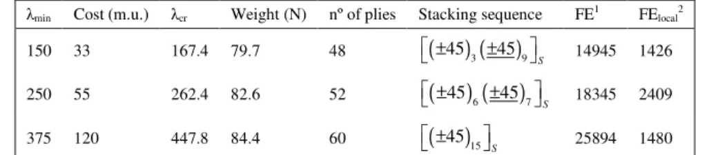
Table 3 also shows the number of function evaluations required by the algorithms proposed by Girard (2006) to achieve the global optimum design. We also note that for optimum laminate configuration the CE layers are placed at the outer surface, which
provides a higher bending stiffness, thus being more effective to satisfy the buckling constraint.
Table 3. Optimal material cost and stacking sequence for the three different minimum buckling load factor (Example 1).
λmin Cost (m.u.) λcr Weight (N) nº of plies Stacking sequence FE1 FElocal2
150 33 167.4 79.7 48
( ) ( )
453 459S
± ±
14945 1426
250 55 262.4 82.6 52
( ) ( )
456 457S
± ±
18345 2409
375 120 447.8 84.4 60
( )
4515S
±
25894 1480
1 mean number of function evaluations to achieve the global optimum without local search, based on 50 independent runs (Girard, 2006) 2 mean number of function evaluations to achieve the global optimum using local search, based on 50 independent runs (Girard, 2006)
In the following, we present a convergence study of this problem comparing the results of the GA developed in this paper with and without the local search. The population size is equal to 20 individuals in all the analysis. The parameters used in the GA are shown in Table 4. They are the same for all the tests pursued. In the material grouping local search, two of individuals among the ten best are chosen per iteration. For the neighborhood search, two individuals are investigated among the five best ones.
Table 4. Probability values used for the GA operators.
Operator Probability crossover 1.00
mutation 0.10
gene swap 0.25
stack add 0.05
stack deletion 0.10
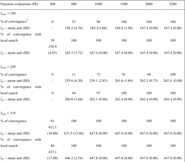
The study is based on 100 independent runs and the stop criterion chosen is the total number of function evaluations (FE). Table 5 shows the obtained results. The mean value and standard deviation (SD) of the buckling load factor are shown to differentiate the case that the algorithm found a solution satisfying all the constraints (defined here as a feasible solution) and when the algorithm reaches the global optimum, which is the design shown in Table 3 for each λmin. Note that to calculate the mean and SD only the feasible solution values are considered.
It can be seen that in all tests the local search accelerates the convergence of the algorithm, reaching the global optimum faster.
Among the cases analyzed, λmin = 250 is the hardest one for the algorithm to converge to the global optimum, once it required the highest number of function evaluations to converge. It can be also seen that, to have 100% of probability of finding the global optimum, the local search reduced such convergence in roughly a thousand function evaluations. For the case where λmin = 150, the local search achieved the global convergence in half of function evaluations.
Considering the number of function evaluations tested, λmin = 375 was the easiest case to solve. In that case, the local search was not as effective or necessary as it was in the other two, meaning that
the harder the optimization is, the more effective the local search may be.
Comparing the results of the three cases with those of Girard (2006) (Table 3), we see that the algorithm without the local search presented in this paper converged much faster (i.e., with a lower number of function evaluations) than the one developed there. Also, its effectiveness can be compared to the algorithm with local search of the reference. Finally, the GA developed here using the local search was the fastest among all.
Example 2: Material Cost Minimization under First Ply Failure and Weight Constraints
The main purpose of this example is to pursue the material cost minimization of a hybrid laminated composite plate comparing the optimal design provided by three different first ply failure criteria: the maximum stress (MS), Tsai-Wu (TW) and the Puck failure criterion (PFC). As in Example 1, the laminate is subjected to symmetry and balance constraints. A maximum weight constraint is also imposed in this example. Thus, the optimization problem reads as follows
Find:
{
θk, mat ,k n}
,θk∈{
0 , 45, 902 ± 2}
,matk∈{
GE, CE}
, k = 1 to n (7)Minimize: Material cost
Subject to: First ply failure constraint: MS, TW or PFC
Maximum weight: 70 N
Let us consider a carbon-epoxy square laminated plate subjected to in-plane loads per unit length Nx = 2.0 N/m (tensile) and Ny = -2.0 N/m (compressive). The plate is analyzed using the classical lamination theory (Jones, 1999).
Table 5. Convergence after 100 independent runs for different number of function evaluations as stop criterion (Example 1).
Function evaluations (FE) 300 500 1000 1500 2000 2500
λmin = 150
% of convergence3 0 53 96 100 100 100
λcr – mean and (SD) - 158.2 (4.76) 165.1(3.66) 166.8 (1.98) 167.4 (0.00) 167.4 (0.00)
% of convergence with
local search 39 100 100 100 100 100
λcr – mean and (SD)
158.9
(4.83) 165.3 (3.72) 167.4 (0.00) 167.4 (0.00) 167.4 (0.00) 167.4 (0.00)
λmin = 250
% of convergence 0 11 73 91 98 100
λcr – mean and (SD) - 255.6 (6.20) 259.1 (2.83) 261.6 (1.60) 262.3 (0.73) 262.4 (0.00)
% of convergence with
local search 0 44 97 100 100 100
λcr – mean and (SD) - 260.0 (3.68) 262.1 (0.60) 262.4 (0.00) 262.4 (0.00) 262.4 (0.00)
λmin = 375
% of convergence 61 100 100 100 100 100
λcr – mean and (SD)
412.1
(18.60) 433.5 (13.60) 447.8 (0.00) 447.8 (0.00) 447.8 (0.00) 447.8 (0.00)
% of convergence with
local search 86 100 100 100 100 100
λcr – mean and (SD)
423.1
(17.80) 446.2 (2.54) 447.8 (0.00) 447.8 (0.00) 447.8 (0.00) 447.8 (0.00)
3can also be interpreted as the probability of finding a feasible solution
Table 6. Strength properties of the layers.
XT
(MPa) XC
(MPa) YT
(MPa) YC
(MPa) S12
(MPa) Ef1
(GPa)
ε1T ε1C νf12 mσf
( ) ||
p⊥+ ( )
|| p⊥−
Carbon-epoxy (CE) 2062 1701 70 240 105 230000 0.0175 0.014 0.23 1.1 0.3 0.25
Glass-epoxy (GE) 1134 1031 54 150 75 72000 0.0302 0.0295 0.22 1.3 0.3 0.25
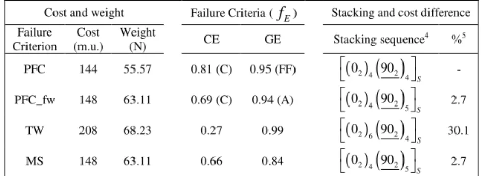
The probabilities of the GA operators are the same as in Example 1, and the optimization results are shown in Table 7. The underlined figures for the orientation correspond to GE stacks, and the remaining figures to CE stacks.
It is interesting to note that the optimum obtained followed the same pattern in every case. All layers with an orientation of 0º are made of CE, while those with an orientation of 90º are made of GE. Note that this problem is independent of the bending stiffness and as a consequence, it is independent of the stacking sequence. Thus, if the stacking sequences shown in Table 7 are rearranged, the laminate extensional stiffness remains the same as long as the number of plies with the same orientation angle and material are kept constant. In addition, the GE laminae were the closest to failure. The cheapest structure was obtained using the PFC, while
the TW criterion resulted in a material cost over 30% higher and yielded the heaviest structure.
Table 7. Optimal material cost and stacking sequence of the laminate for different failure criteria (Example 2).
Cost and weight Failure Criteria (
f
E) Stacking and cost differenceFailure Criterion
Cost (m.u.)
Weight
(N) CE GE Stacking sequence
4 %5
PFC 144 55.57 0.81 (C) 0.95 (FF)
( )
02 4( )
902 4 S
-
PFC_fw 148 63.11 0.69 (C) 0.94 (A)
( )
02 4( )
902 5 S
2.7
TW 208 68.23 0.27 0.99
( )
02 6( )
902 4 S
30.1
MS 148 63.11 0.66 0.84
( )
02 4( )
902 5 S
2.7
4
any order of this combination of orientation and material gives the same response 5
relative weight difference (percentage difference in relation to the weight obtained using the PFC) predicted by the failure criteria
Concluding Remarks
In this paper, a genetic algorithm was developed to pursue the optimization of hybrid laminated composite structures. The GA was chosen as an optimization tool because of its ability to deal with non-convex, multimodal and discrete optimization problems, of which the design of laminated composites is an example. First, the developed algorithm was validated by comparing its results to those obtained from the literature. Then, the maximum stress, Tsai-Wu and Puck failure criteria (PFC) were used as constraint in the optimization process and the results yielded by them were compared.
The results of this study show that the developed algorithm converges faster than the one found in the literature and that the local search accelerates the convergence. Moreover, the harder the problem is, the more effective the local search is.
Regarding the different first ply failure criteria, it was found that each criterion yields a different optimal design. Therefore, when optimizing laminated composite structures, the choice of a failure criterion corresponding to the real behavior of the structure is crucial for both economy and safety.
Acknowledgements
The first author is supported by the Programme Alban, the European Union Programme of High Level Scholarships for Latin America, scholarship no. E07D401224BR.
References
Antonio, C., 2001, “A multilevel genetic algorithm for optimization of geometrically nonlinear stiffened composite structures”, Structural and Multidisciplinary Optimization, Vol. 24, pp. 372-386.
Antonio, C., 2006, “A hierarchical genetic algorithm with age structure for multimodal optimal design of hybrid composites. Structural and Multidisciplinary Optimization”, Vol. 31, pp. 280-294.
Arora, J.S., 2004, “Introduction to Optimum Design”, 2nd ed., Elsevier Academic Press, San Diego, USA.
Daniel, I.M., 2007, “Failure of Composite Materials”, Strain, Vol. 43, pp. 4-12.
Girard, F., 2006, “Optimisation de Stratifiés en Utilisant un Algorithme Génétique”, Master’s Dissertation, Faculté des Sciences et Génie, Université Laval, Québec, Canada.
Groenwold, A. and Haftka, R., 2006, “Optimization with non-homogeneous failure criteria like Tsai–Wu for composite laminates”, Structural and Multidisciplinary Optimization, Vol. 32, pp. 183-190.
Gürdal, Z., Haftka, R.T. and Hajela, P., 1999, “Design and Optimization of Laminated Composite Materials”, John Wiley & Sons, Inc., New York, USA.
Jones, R.M., 1999, “Mechanics of Composite Materials”, 2nd ed., Taylor and Francis, Philadelphia, USA.
Le Riche, R. and Haftka, R., 1993, “Optimization of laminate stacking sequence for buckling load maximization by genetic algorithm”, AIAA Journal, Vol. 31, pp. 951-956.
Le Riche, R. and Haftka, R., 1995, “Improved genetic algorithm for minimum thickness composite laminate design”, Composites Engineering, Vol. 5, pp. 143-161.
Liu, B., Haftka, R., Akgun, M. and Todoroki, A., 2000, “Permutation genetic algorithm for stacking sequence design of composite laminates”, Computer Methods in Applied Mechanics and Engineering, Vol. 186, pp. 357-372.
Mathias, J.D., Balandraud, X. and Grediac, M., 2006, “Applying a genetic algorithm to the optimization of composite patches”, Computers & Structures, Vol. 84, pp. 823-834.
Murugan, M.S., Suresh, S., Ganguli, R. and Mani, V., 2007, “Target vector optimization of composite box beam using real-coded genetic algorithm: a decomposition approach”, Structural and Multidisciplinary Optimization, Vol. 33, pp. 131-146.
Nagendra, S., Jestin, D., Gürdal, Z., Haftka, R. and Watson, L., 1994, “Improved genetic algorithm for the design of stiffened composite panels”, Computers & Structures, Vol 58, pp. 543-555.
Naik, G.N., Gopalakrishnan, S. and Ganguli, R., 2008, “Design optimization of composites using genetic algorithms and failure mechanism based failure criterion”, Composite Structures, Vol. 83, pp. 354-367.
Puck, A., 1996, “Festigkeitsanalyse von Faser-Matrix-Laminaten: Modelle für die Praxis”, München,. Wien, Hanser.
Puck, A. and Schürmann, H., 1998, “Failure analysis of FRP laminates by means of physically based phenomenological models”, Composites Science and Technology, Vol. 58, pp. 1045-1067.
Puzzi, S., Carpinteri, A., 2008, “A double-multiplicative dynamic penalty approach for constrained evolutionary”, Structural and Multidisciplinary Optimization, Vol. 35, pp. 431-445.
Schmitt, L.M., 2001, “Theory of genetic algorithms”, Theoretical Computer Science, Vol. 259, pp. 1-61.
Seresta, O., Gürdal, Z., Adams, D.B. and Watson, L.T., 2007, “Optimal design of composite wing structures with blended laminates”, Composites Part B: Engineering, Vol. 38, pp. 469-480.
Todoroki, A. and Haftka, R., 1998, “Stacking sequence optimization by a genetic algorithm with a new recessive gene like repair strategy”, Composites Part B: Engineering, Vol. 29, pp. 277-285.