Short Report
*e-mail: [email protected]
Active Pt-PbO
x/C Anodes to Promote the Formic Acid Oxidation
in Presence of Sulfuric Acid
Guilherme S. Buzzo,a Rafael V. Niquiriloa and Hugo B. Suffredini*,a
aCentro de Ciências Naturais e Humanas, Universidade Federal do ABC,
Rua Santa Adélia, 166, Bairro Bangu, Santo André-SP, Brazil
Este trabalho propõe estudar ânodos baseados em Pt e PbOx frente à reação de oxidação do ácido
fórmico. Os materiais estudados foram sintetizados por uma metodologia sol-gel adaptada. Estudos voltamétricos mostraram que o processo de oxidação ocorre em potenciais extremamente baixos. Este bom desempenho foi comprovado por meio de curvas de polarização e cronoamperometrias.
The performance of Pt-PbOx-based catalysts to promote the formic acid oxidation is described
here. All materials were synthesized by a modiied sol-gel method. Voltammetric studies showed
that the Pt-PbOx/C anode starts the oxidation process at extremely low potentials. Quasi-stationary
polarization experiments and current vs. time measurements conirmed this afirmation.
Keywords: lead oxide-based catalysts, Pb, formic acid oxidation, modiied sol-gel method,
energy.
Introduction
Direct formic acid fuel cells are promising devices for the production of electrical energy in portable devices. Formic acid is non-inlammable liquid, used as additive in food and its transportation are less dangerous than for aliphatic alcohols.1 On the other hand, formic
acid is corrosive and its storage must be done with discretion.
Compared speciically with methanol, other advantage of using formic acid is the lower cross-over effect through the polymer membrane. For this reason, the concentration of the fuel can achieve about 20 mol L-1 of concentration
for the formic acid and only 2 mol L-1 for the methanol,
due to the problems related with the Naion® membrane.2
Taking this factor into account, the power density of direct formic acid fuel cells (DFAFC) is higher than that observed for DMFC, despite the energy density of methanol being a third higher than that of formic acid.3
Several oxidation mechanisms were proposed concerning the formic acid oxidation. One of the most accepted mechanisms is presented below. The formic acid oxidation can undergo two parallel pathways on platinum (with or without the CO adsorption step).4 In the irst one,
called the “direct pathway”, the acid is directly oxidized to carbon dioxide:
Pt
HCOOH → CO
2 + 2H+ + 2e- (1)
In the second possibility, the mechanism occurs by one chemical and two electrochemical steps, initialized with the CO adsorption on the Pt surface:
HCOOH + Pt → Pt-CO + H
2O (2)
Pt + H2O → Pt-OH + H+ + e- (3)
Pt-CO + Pt-OH → 2Pt + CO
2 + H+ + e- (4)
The overall reaction is
HCOOH → CO
2 + 2H+ + 2e- (5)
Several reports appear in the literature concerning formic acid oxidation. Lee et al. studied the effect of the Au composition for formic acid oxidation on AuPt catalysts, using a linear sweep voltammetry technique in a 0.5 mol L-1 H
2SO4 +1 mol L-1 HCOOH solution.5 In
performance of DMFC and DFAFC systems.6 Selvaraj et al.
reported the high eficiency of a catalyst based on Pt and PtPd to promote formic acid and formaldehyde oxidation,7
while Jeong et al. discussed the cross-over affect in direct formic acid fuel cells.8
In the 1970’s, Adzic and co-authors published important papers related to this subject.9-11 In one of these studies,
the authors observed the increase of the catalytic response, using a Pt-Pb system synthesized by the UPD technique, and compared the results with a bare Pt electrode.10 Other systems
studied by the same authors are related to the catalytic performance of foreign noble metals, Pd monolayers on Pt, and the application of pulsing potentials to avoid the poisoning effects related to formic acid oxidation. Other UPD systems were studied by different authors.12-16
More recently, Pd and Pd alloys have appeared in the literature with very interesting results.17-19 Following
this subject, Waszczuk et al. synthesized nanoparticles containing Pd, Ru and Pt.20 In this study, the Pt/Pd catalyst
shows the best performance. Casado-Rivera et al. observed that a signiicant number of the ordered intermetallic phases exhibited enhanced electrocatalytic activity when compared to that of Pt, in terms of both oxidation onset potential and current density, in particular, PtPb electrodes.21 Tripkovic
et al. demonstrated that a PtBi catalyst starts formic acid oxidation at 0.25 V less positive potential, in comparison with polycrystalline Pt.22
As demonstrated, the synergetic effects of lead in anodes have been widely discussed in the literature, but the use of lead oxides (PbOx) to promote formic acid oxidation are being presented and discussed for the irst time in this paper.
In order to produce the catalysts, several techniques of deposition have been proposed to ix Pt, other metals or metallic oxides onto different substrates. One of the most widely used techniques was proposed by Bönnemann.23
Some reports published recently demonstrated that an adaptation of the traditional sol-gel constitutes an eficient and simple technique to produce anodes containing Pt , Ru and Pb with the desired composition.24,25
Thus, the aim of this work is to use these previously prepared catalysts, deposited by the sol-gel method on carbon powder and ixed on a glassy carbon substrate, to promote formic acid oxidation in the presence of sulfuric acid. The physical characterization of this material (performed by X-ray diffraction (XRD) and energy dispersive X-ray (EDX) analysis) was described in a previous work.25 The electrochemical studies of formic
acid oxidation were carried out by cyclic voltammetry, chronoamperometry and quasi-stationary polarization curves, carried out in potentiostatic mode (Tafel plots).
Experimental
Reagent, apparatus and preparation of the precursors
A conventional one compartment Pyrex® glass cell
provided with three electrodes was used to promote all electrochemical studies. The cell was constituted by the Hydrogen Electrode in the Same Solution (HESS) as reference, a Pt foil (2 cm2) as auxiliary and a glassy carbon
as working electrode, as support for the modiied powders. The substrate was previously polished with alumina and washed with isopropylic alcohol. The supporting electrolyte was a H2SO4 0.5 mol L-1 solution (Merck®) also containing,
in some cases, formic acid 1.0 mol L-1 (Synth®). The
electrochemical measurements were carried out using an AUTOLAB PGSTAT 100 equipment.
The preparation of the precursors is described below. As an example, the platinum solution was prepared adding 9.9 x 10⁻³ g of the Pt (II) acetylacetonate (Aldrich®) to
25 mL of a liquid mixture constituted by ethanol (Synth®
98o) and acetic acid (Merck® P.A.) 3:2 (v/v), while the
lead and ruthenium solutions were prepared using the same procedure but adding the necessary acetylacetonates quantities (Aldrich®). The inal concentration of each
solution was 1.0 x 10⁻³ mol L-1. The carbon black powder
used was Vulcan® XC72R, and 5% commercial Naion®
solution (DuPont) was purchased from Aldrich®. The
normalization of the currents were carried out according to the mass of Pt deposited on the carbon powder for the Pt-PbOx/C and Pt-(PbOx-RuO2)/C catalysts (generating pseudo-current densities) or considering the quantity of 2.0 x 10⁻⁹ mol Pt cm-1 (medium value for polycrystalline
Pt) for the working polycrystalline Pt electrode (geometric area = 2.0 cm2, roughness factor = 4.5, real area = 9 cm2).
The roughness factor was determined by the hydrogen desorption process on the Pt electrode in sulfuric acid.
Modiied Carbon Powder Preparation
The composites containing Pt, Ru, Pb and C were prepared using ixed mass proportion of metals Pt:Pb (50:50), Pt:Ru:Pb (50:25:25) and carbon powder as a support. The catalyst mass load was ixed at 10% with respect to the carbon powder.
All depositions were carried out according to a procedure reported elsewhere,25 by putting the dry carbon
added in 1 mL aliquots. This procedure was repeated until a load of 10% catalysts was attained. The carbon powder was then subjected to a thermal treatment at 400 °C for 1 h under an argon atmosphere, to avoid the oxidation of the C to CO2.
It is important to observe that the suspension of the particles (or the formation of a colloidal solution) was not controlled. So, the kind of solution studied in this work cannot be called as “sol”. It is not possible to conclude that the modiication of the carbon black represents a direct sol-gel modiication. Thus, the process is an adaptation of the traditional sol-gel process.
Fixation of the powder onto a glassy carbon substrate
The synthesized composites were ixed onto a glassy carbon electrode (geometric area = 0.5 cm2), following the
procedure described irstly by Schmidt et al.26 Firstly, a
5 wt.% Naion solution was diluted ten times in deionised water. Then, 0.008 g of the composite was added to 1 mL of water and 0.20 mL of the diluted Naion® solution. The
resulting system was placed in an ultrasonic bath for 3 min to disperse the powder in the Naion® solution. Finally,
0.02 mL of the obtained dispersion was transferred onto a glassy carbon electrode with geometric area of 0.125 cm2.
The deposited suspension was then dried for 60 min at 80 °C to complete evaporation of the solvents.
Results and Discussion
Physical Characterization
As previously noted, the Pt-PbOx/C and Pt-(PbOx -RuO2)/C catalysts were the same used to promote the ethanol oxidation in a recent publication.25 The materials
were previously characterized by X-ray diffraction (XRD) to verify the presence of the oxides and metal onto a carbon powder, determining a posteriori the crystallite dimensions using WinFit 1.0 software and energy dispersive X-ray analysis (EDX) to promote a semi-quantitative determination of the metals in the catalysts.
In short, the XRD patterns obtained for all composites prepared in this work, together with the corresponding indication of the main peaks and their identiication by comparison with the JCPDS (Joint Committee of Power Diffraction Standards) cards, are presented. The Pt was deposited as a metal in the polycrystalline form, showing the peaks corresponding to the main three crystallographic planes (111), (200) and (220). Ruthenium was deposited as RuO2 and, in addition, Pb was deposited as a mixture of PbO and PbO2. Thus, the nomenclature of all Pb containing
compounds is designated by “PbOx”. The EDX analyses revealed that Pb is preferentially deposited in relation to Pt, while for the other composites that were studied, a very good agreement between the experimental and the expected theoretical values is observed. Furthermore, the values of the crystallite dimensions obtained with the software ranged from 3.5 nm to 4.0 nm for all compounds.
Electrochemical Studies
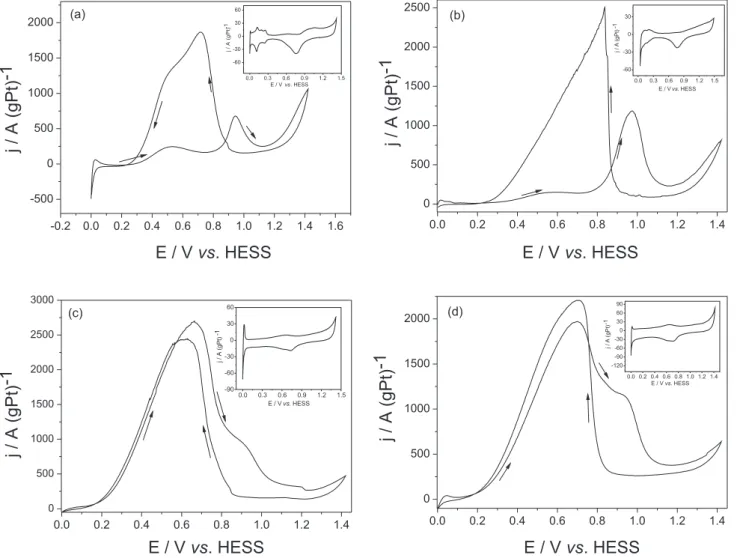
Figure 1 shows the cyclic voltammetric responses studies carried out in H2SO4 0.5 mol L-1 + HCOOH
1.0 mol L-1 solution for polycrystalline Pt (a), Pt/C (b),
Pt-PbOx/C (c) and Pt-(PbOx-RuO2)/C (d). The inserts of the igures represents the electrochemical responses in H2SO4 0.5 mol L-1. The presence of Pt in both lead-based
catalysts can be observed due to the inhibited signals of the adsorption-desorption of hydrogen on the exposed Pt in each material. It is important to observe this process, as it is a fundamental parameter that conirms there are no problems (such as potential dislocation) with the reference electrode.
In this way, Figure 1(a) presents the electrochemical responses (after 3 cycles) for the polycrystalline Pt. This material starts the formic acid oxidation at about 0.4 V vs. HESS, presenting inhibited oxidation currents, due to the strong CO adsorption process (Eq. 2). In fact, several authors mentioned that formic acid oxidation occurs by the indirect route on polycrystalline Pt, with chemical adsorption of CO on the electrode surface.2-4 The CO
oxidation can be observed at about 0.9 V vs. HESS, making polycrystalline Pt unviable as an anode in DFAFC’s. In the same way, Figure 1 (b) shows the response of a Pt/C catalyst (10% of catalyst load), synthesized by a modiied sol-gel method. The electrochemical behavior is quite similar to that observed with the polycrystalline Pt electrode (Figure 1a) starting the reactions at the same potentials, indicating that the oxidation also occurs by the CO adsorption mechanism. The Pt/C anode was studied because it represents a more realistic system to be used in a real fuel cell system.
catalysts based in PtBi and PtPb present very good catalytic activity for formic acid oxidation, but these materials have no practical applications in DFAFCs, due to the applied methodology of synthesis (underpotential deposition of Pb in Pt).22 Thus, the use of PbO
x/C as catalyst can be a good
choice in real fuel cell systems. The voltammetry proile of the Pt-PbOx/C catalyst can be compared with metallic Pd, which constitutes the state-of-the-art material to this kind of application.17-19
Concerning the Pt-(PbOx-RuO2)/C catalyst, it is possible to observe in Figure 1(d) that the curve did not present signiicant differences when compared with the Pt-PbOx/C anode. The Pt-(PbOx-RuO2)/C catalyst presents only about 82% of the pseudo-currents densities when compared with the Pt-PbOx/C anode in the same conditions. The increase of the oxidation process at about 0.9 V vs. HESS observed for the Pt-(PbOx-RuO2)/C can be related to the Ru(II)/ Ru(III) transition (dotted line) and similar responses were observed by other authors in different works.27-28 Other
possibility is related to the increase of the oxidation of adsorbed carbon monoxide (CO) on the electrode surface when compared with the Pt-PbOx/C anode. Abruña and co-authors have studied the CO oxidation using ordered intermetallic electrodes and the CO oxidation process was observed in that same range of potentials.29 Thus, it
is possible to conclude that the RuO2 can be eliminated from the composition, because is not possible to justify its utilization.
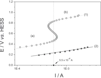
The interesting performance of the anode constituted by Pt-PbOx/C for the formic acid oxidation encouraged the study in quasi-stationary conditions. To properly determine and compare the onset potential values for the formic acid oxidation, a minimum value of current was ixed. All onset potential values discussed and obtained from Figure 2 were taken at 5.5 x 10⁻⁴ A.
Thus, Figure 2 shows the quasi-steady state polarization curves presented as Tafel plots that were carried out in potentiostatic mode, at 20o C in H
2SO4 0.5 mol L-1 + Figure 1 – Cyclic voltammetric responses (after three cycles) carried out in H2SO4 0.5 mol L-1 + HCOOH 1.0 mol L-1 solution for polycrystalline Pt (a), Pt/C (b), Pt-PbOx/C (c) and Pt-(PbOx-RuO2)/C (d). v = 20 mVs-1. All inserts represent the electrochemical responses in H
HCOOH 1.0 mol L-1 aqueous solution. It can be observed
that the polycrystalline Pt (curve 1) presents two linear Tafel regions. The irst one (process “a”), related to the formic acid oxidation, presented a Tafel slope at about 145 mV dec-1, and the onset oxidation potential was
0.44 V vs. HESS at 5.5 x 10⁻⁴ A of current. The second one, probably related to the CO oxidation, showed a Tafel slope of about 150 mV dec-1 and an onset oxidation potential of about
0.84 V vs. HESS. In both cases, the rate determining step (rds) is related to a one-electron electrochemical step (Tafel slopes about 120 mV dec-1). In the same way, curve 2
presents the Tafel plot for the Pt-PbOx/C catalyst. In this case the slope was of the order of 128 mV dec-1 and the
onset potential was about 0.23 V vs. HESS. In agreement with the cyclic voltammetry measurements presented in Figure 1, the Pt-PbOx/C catalyst presented somewhat about 200 mV less positive potential for the formic acid oxidation, in quasi-stationary conditions.
Figure 3 presents current vs. time studies (at 0.3 V vs. HESS) carried out in H2SO4 0.5 mol L-1 + HCOOH 1.0 mol L-1 solution for the Pt-PbO
x/C (a), Pt-(PbOx
-RuO2)/C (b), Pt/C (c) and polycrystalline Pt (d). A low potential was chosen because the system produces many bubbles during the oxidation process for the active materials. The Pt-PbOx/C (a) and Pt-(PbOx-RuO2)/C (b) exhibit higher pseudo-current densities for the same applied potential at the studied time. On the contrary, the curves related to the Pt/C and polycrystalline Pt tend to zero. Slower and continuous current decays are also observed in the Pt-(RuO2-PbOx)/C and Pt-PbOx/C catalysts, due probably to a smaller poisoning of the material as the process advances.
Thus, in view of the interesting catalytic activities observed on the Pt-PbOx/C catalyst, further studies will be carried out to understand the oxidation mechanism.
Conclusions
Cyclic voltammetry studies show that the electrochemical oxidation of formic acid presented high pseudo-current densities on the Pt-PbOx/C and Pt-(PbOx-RuO2)/C catalysts, starting the process at a very low potential, while Pt/C, as expected, cannot be used as an anode in DFAFCs due to the strong CO afinity of the material. The comparison between Pt-PbOx/C and Pt-(PbOx-RuO2)/C catalysts demonstrates that RuO2 does not present any important synergistic effect that justiies its utilization.
Moreover, quasi-steady state polarization curves conirmed that the Pt-PbOx/C catalyst started the oxidation process at very low potentials (0.25 V vs. HESS, somewhat about 200 mV less positive potential for the formic acid oxidation when compared with Pt), presenting a satisfactorily performance to promote formic acid oxidation in quasi-stationary conditions. On the contrary, the polycrystalline Pt and Pt/C anodes show a non-synergic behavior, due to the strong afinity of CO to this metal. Finally, the current-time measurements indicate that the Pt-PbOx/C catalyst could be an interesting material to be used as anode in direct formic acid fuel cell systems, presenting a stationary pseudo-current density of about 250 A (gPt)-1
after 1500 s of oxidation at 0.3 V vs. HESS.
Acknowledgments
We thank FAPESP (2007/05155-1), CNPq (472476/2008-4 and 301863/2008-3), CAPES and UFABC-PRPG for providing G.S. Buzzo and R.V. Niquirilo with scholarships.
Figure 2 – Tafel Plots recorded in potentiostatic mode in H2SO4 0.5 mol L-1 + HCOOH 1.0 mol L-1 for: Polycrystalline Pt (circles, curve 1) and Pt-PbOx/C (stars, curve 2). T = 20 oC. Curve 1 shows two different kinetic-controlled processes: formic acid oxidation (a) and, probably, carbon monoxide oxidation (b).
Figure 3 – Current-time responses (at 0.3 V vs. HESS) carried out in H2SO4 0.5 mol L-1 + HCOOH 1.0 mol L-1 solution for Pt-PbO
References
1. Wang, X.; Tang, Y.; Gao, W.; Lu, T.; J. Power Sources2008,
175, 784.
2. Rhee,Y. W.; Ha, S. Y.; Masel, R. I.; J. Power Sources2003,117, 35.
3. Zhu, Y. M.; Ha, S. Y.; Masel, R. I.; J. Power Sources2004, 130, 8.
4. Rice, C.; Ha, S.; Masel, R. I.; Wieckowski, A.; J. Power Sources 2003,115, 229.
5. Lee, J. K.; Lee, J.; Han, J.; Lim, T-H.; Sung, Y-E.; Tak, Y.
Electrochim. Acta2008, 53, 3474.
6. Uhm, S.; Chung, S. T.; Lee, J. J. Power Sources2008, 178, 34. 7. Selvaraj, V.; Alagar, M.; Kumar, K. S.; App. Catal. B2007, 75,
129.
8. Jeong, K-J.; Miesse, C. M.; Choi, J-H.; Lee, J.; Han, J.; Yoon, S. P.; Nam, S. W.; Lim, T-H.; Lee, T. G. J Power Sources2007,
168, 119.
9. Adzic, R. R.; Simic, D. N.; Drazic, D. M.; Despic, A. R.;
J. Electroanal. Chem. Interf. Electrochem.1975, 61, 117. 10. Adzic, R. R., Simic, D. N., Despic, A. R., Drazic, D. M.
J. Electroanal. Chem.1977, 80, 81.
11. Adzic, R. R.; O’Grady, W. E.; Srinivasan, S.; J. Electrochem. Soc.1981, 128, 1913.
12. Beltowska-Brzezinska, M.; Heitbaum, J.; Vielstich, W.;
Electrochim. Acta1985, 30, 1465.
13. Campbell, S. A.; Parsons, R. J. Chem. Soc. Faraday Transactions 1992, 88, 833.
14. Kelaidopoulou, A.; Abelidou, E.; Kokkinidis, G.; J. Appl. Electrochem. 1999, 29, 1255.
15. Lei, H. W.; Hattori, H.; Kita, H.; Electrochim. Acta1996, 41, 1619.
16. Mikhailova, A. A.; Osetrova, N. V.; Vasilev, Y. B.; Soviet Eletrochem. 1989, 25, 1612.
17. Ha, S.; Larsen, R.; Masel, R. I.; J. Power Sources2005, 144, 28.
18. Larsen, R.; Zakzeski, J.; Masel, R. I.; J. Electrochem. Solid-State Lett.2005, 8, 291.
19. Zhu, Y. M.; Khan, Z.; Masel, R. I.; J. Power Sources2005, 139, 15.
20. Waszczuk, P.; Barnard, T. M.; Rice, C.; Masel, R. I.; Wieckowski, A.; Electrochem. Commun. 2002, 4, 599.
21. Casado-Rivera, E.; Volpe, D. J.; Alden, L.; Lind, C.; Downie, C.; Vazquez-Alvarez, T.; Angelo, A. C. D.; DiSalvo, F. J.; Abruna, H. D.; J. Am. Chem. Soc.2004, 126, 4043.
22. Tripkovic, A. V.; Popovic, K. Dj.; Stevanovic, R. M.; Socha, R.; Kowal, A. Electrochem. Commun.2006, 8, 1492. 23. Bonnemann, H.; Brijoux, W.; Brinkmann, R.; Dinjus, E.;
Fretzen, R.; Jouben, T.; Korall, B.; J. Molec. Cat.1992, 74, 323. 24. Suffredini, H. B.; Salazar-Banda, G. R.; Avaca, L. A.; J. Sol-Gel
Sci. Technol. 2009, 49, 131.
25. Suffredini, H. B.; Salazar-Banda, G. R.; Avaca, L. A.; J. Power Sources2007, 171, 355.
26. Schmidt, T. J.; Gasteiger, H. A.; Stab, G. D.; Urban, P. M.; Kolb, D. M.; Behm, R. J.; J. Electrochem. Soc.1998, 145, 2354. 27. Terezo, A. J.; Pereira, E. C.; Mater. Lett.2002, 53, 339.
28. Mattos-Costa, F. I.; de Lima-Neto, P.; Machado, S. A. S.; Avaca, L.A. Electrochim. Acta 1998, 44, 1515.
29. de-los-Santos-Álvarez, N.; Alden, L. R.; Rus, E.; Wang, H.; DiSalvo, F. J.; Abruña, H. D.; J. Electroanal. Chem.2009, 626,
14.
Received: July 3, 2009
Web Release Date: October 23, 2009