Review Article
2 6 7 Arq Bras Oftalmol. 2014;77(4):267-70 http://dx.doi.org/10.5935/0004-2749.20140068
INTRODUCTION
He who faces the challenge of learning visual optics is often tor-tured by questions that the concept of ray bundles fails to answer, such as: Why does a divergent bundle of rays becomes parallel at in-finity? Why does the angular aperture of a diverging bundle not mea-sure its vergence? What is the meaning of vergence? Is it a meamea-sure of curvature or power? While the answers to these questions have been determined, they are not readily accessible. Instead, they are scattered throughout the literature left by brilliant astronomers and mathematicians over the centuries. The objective of this paper is to compile the answers to some of these questions and in the process, introduce some concepts underexplored in texts of visual optics.
L
IGHT“The night was so dark we could see nothing”. This sentence of everyday life straightforwardly unveils one of the most basic facts of visual optics: there is no vision without light. For an object to be viewed, it has to send out light. The light needs not to be self-ge-nerated; it may be reflected from another source. When it strikes the eye it is deflected by the cornea and crystalline lens to form an upside-down image on the retina. There, it is converted into nerve impulses that are sent to the occipital cortex, where they become a visual impression. To achieve good vision, all the events involved in the transmission of visual information, from the light source to the occipital cortex, have to occur faultlessly. Visual optics is specifically concerned with those factors that influence the quality of retinal images.
It is remarkable that this sequence of events had already been described by the French mathematician René Descartes in 1637(1-3). His intuition was so accurate that his views on this subject were only recently revised(3-6).
L
IGHTSOURCESLight sources are sites of light. They can be luminous or non-lumi-nous. The former emit their own light, such as the sun, light bulbs, and fire(7). The latter simply reflect received light. They include either the irregular surfaces of ordinary objects that reflect light diffusely (balls, shoes, paintings), or images of lenses and curved mirrors.
In 1604 Johannes Kepler, a German astronomer, postulated that an extended object can be interpreted as composed of myriads of points, each acting as a source point of light(8,9). When light is refracted by a lens, the final image represents the sum of the refractions of each of these points. This assumption greatly simplified the study of optics, since instead of analyzing the refraction of all points of an object, one has only to choose a representative one and generalize the findings. The point of a source taken as a reference is called an object point when it emits light, and an image pointwhen it receives light. For instance, the image formed by a lens is composed of image points that receive the refracted light. However, if these image points are chosen to provide light to a second lens, they become object points to this lens.
Every object point is linked to an image point and vice versa. They become conjugated by refraction of light the same way two people become related by marriage. The distance from the lens to the object
Visual optics under the wavefront perspective
Óptica visual sob a perspectiva das frentes de onda
Sidney Júlio Faria-e-SouSa1, GuStavo victor1, Milton ruiz alveS2
Submitted for publication: June 16, 2014 Accepted for publication: June 18, 2014
Study conducted at Departamento de Oftalmologia, Universidade de São Paulo (USP).
1 Departamento de Oftalmologia, Faculdade de Medicina, Universidade de São Paulo (USP), Ribeirão Preto, SP, Brazil.
2 Departamento de Oftalmologia, Faculdade de Medicina, Universidade de São Paulo (USP), São Paulo, SP, Brazil.
Funding: No specific financial support was available for this study.
Disclosure of potential conflicts of interest: None of the authors have any potential conflicts of interest to disclose.
Corresponding author: Sidney J. Faria-e-Sousa. Av. Bandeirantes, 3.900 - Ribeirão Preto - SP - 14049-900 - Brazil - E-mail: [email protected]
RESUMO
Alguns conceitos intrigantes da óptica visual não podem ser explicados pelo traçado dos raios luminosos. Entretanto, eles podem ser esclarecidos através do formalismo da frente de onda. A vantagem do mesmo está no uso do conceito de vergência, que facilita o entendimento dos fenômenos ópticos envolvidos na neutralização das ametropias. Nessa linha de raciocínio, a principal função de uma lente é o de criar de uma nova fonte de luz - o ponto de imagem - que orienta as ondas refratadas. Conhecendo-se a natureza e a posição dessa fonte pode-se facilmente prever o comportamento das frentes de onda. Este formalismo também ajuda a compreensão de como as frentes de onda se relacionam com os raios de luz e como os sinais algébricos são atribuídos às distâncias ópticas.
Descritores: Erros de refração/diagnóstico; Refração ocular/fisiologia; Óptica e fo-tônica; Aberrações de frente de onda da córnea; Matemática; Luz
ABSTRACT
Some intriguing concepts of visual optics cannot be explained by ray tracing. However, they can be clarified using wavefront formalism. Its main advantage is in the use of the concept of vergence, which is very helpful in interpreting the optical phenomena involved in the neutralization of the ametropias. In this line of thinking, the major role of a lens is in the creation of a new light source (the image point) that orientates the refracted waves. Once the nature and position of this source is known, one can easily predict the behavior of the wavefronts. The formalism also allows for an easier understanding on how wavefronts relate to light rays and on how algebraic signs are assigned to optical distances.
Visual optics under the wavefront perspective
2 6 8 Arq Bras Oftalmol. 2014;77(4):267-70
point is called the object distance and the distance from the lens to the image point is called the image distance. Since the lens is the associative agent, distances are measured from it.
W
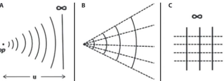
AVEFRONTSIn 1801 Thomas Young(10-12), an English scientist, established the wave theory of light, which had been formulated in the seventeenth century by the Dutch astronomer Christiaan Hoygens(13,14). In this approach, any object point emits spherical waves with convex wa-vefronts. As the wave train moves away from its’ source it expands, becoming ever less curved (Figure 1A). The distance of the wavefront to the object point is the object distance. It is also its radius of curvature. The reciprocal of this distance is the curvature of the wave surface. Representing the object distance (or the radius of curvature) by u and the curvature of the wavefront by U, the relation between them is:
By convention, convex wavefronts are diverging surfaces with ne gative curvatures. If a wavefront is diverging, one must replace u in Formula 1 with a negative number.
When the distance from the wavefront to the object point approa-ches infinity, the curvature of the wave surface approaapproa-ches 1/∞, or zero. A wavefront with zero curvature is flat (Figure 1A).
When a lens modifies the curvature of an incoming wavefront as a result of refraction, an exiting wavefront is created along with a new source of light that is linked to it. This new source is called an image point. This is especially important because it becomes the reference point for the refracted wave train.
If the wavefront that strikes the lens is flat, the image point is uni -que, because it is conjugated to the infinity. In this special case, any curvature showed by the exiting wavefront is due to the lens (Figure 2). The image point conjugated to the flat wavefront receives the distinguished name of focus.
The distance from the lens to the focus is the focal length. The reciprocal of this variable stands for the bending capability of a lens placed in a vacuum or in air. Representing this variable by F and the focal lens by ƒ, the relation between them is:
If the profile of the wavefront that emerges from the lens is con-cave, ƒ is positive; if convex, ƒ is negative.
Real object points do not emit concave wavefronts. These wave-fronts are generated by the refraction of light trough convex lenses. Once created, they converge to an image point. On their way, they bend and contract gradually until they become a single point (Figure 3). The distance from the lens to the image point is the image distance. It is also the radius of curvature of the refracted wavefront at the lens
plane. Representing the image distance by v and the curvature of the wavefront by V, the relation between them is:
By convention, concave wavefronts are converging surfaces with positive curvatures. If a wavefront is converging, we must replace v in Formula 3 with a positive number.
C
URVATUREANDRADIUSOFCURVATUREFrom a geometrical standpoint, u, ƒ, and v are the radii of
cur-vature of spherical surfaces. The reciprocals of these distances are the curva tures of the corresponding surfaces(15). The unit of measu-rement of curvature is the meter(16). In visual optics, it is a common practice to express curvature in diopters (D)(17). Technically, this is not a unit of curvature, but of vergence. This metaphorical extension is probably derived from the perception that curvatures and vergences are numerically identical in air. Thus, a wavefront placed 0.4 m to the right of an object point will have a curvature of 1/-0,4 = -2,5 D (Figure 3). The distance is negative because real objects always emit diverging waves. If this distance were given in another unit, it would have to be converted to meters to allow for the use of the diopter.
V
ERGENCEOFLIGHTThe light propagated from a point object loses curvature evenly as it moves toward infinity. Lenses can modify the natural course of propagation by refraction. As previously mentioned, the resulting wavefront breaks its link to the original source and joins another source: the image point (Figure 3).
Figure 1. Waves and rays. A) Diverging convex wavefronts; op: object point; u: object
distance. B) A diverging bundle of rays (dashed lines) perpendicular to curved wavefronts (the rays form the igure of a fan). C) Flat waves at ininity (solid vertical lines) generating a bundle of parallel rays, perpendicular to the wavefronts (dashed lines).
A B C
Figure 2. Refraction in a convex lens. ip: real image point, which is also the focus of the
lens, because the light comes from ininity; f: real focal distance; a and b are respectively lat and concave wavefronts.
Figure 3. Refraction of light through a + 3 D lens. u: object distance; v: image distance;
Faria-e-Sousa SJ, et al.
2 6 9 Arq Bras Oftalmol. 2014;77(4):267-70 The vergence of a lens is the power it has to modify the curvature
of a wavefront, and the vergence of a wavefront is the power it has to resist the lens action. The result of the refraction depends on the interplay between these two powers. The interaction is positive when the lens increases the curvature of the wavefront, and is negative when it decreases or inverts it.
Vergence, either of a lens or a wavefront, increases with the curva-ture of the surface and with the optical density of the medium the light travels through. Numerically, the vergence of a surface is the product of the curvature and the index of refraction of the medium (n). Vergence is also measured in diopters (D).
The optical density of the medium through which the light travels increases vergence by increasing the compression of the wave trains(18). Compressed waves (with shorter wavelengths) are less liable to further compression by a lens, which makes them less compliant to the lens action. In other words, compressed wave trains have more energy to sustain their natural course(19). This is also the reason why blue light has more vergence than red light: the former is more compressed than the later.
When the index of refraction is close to the unit (n ≅ 1), as in a vacuum or air, vergences and curvatures become numerically interchangea-ble. Yet this does not mean they are identical. Curvature measures the bending of a surface, while vergence measures the effect of the bending on the refraction. Wavefronts with the same radius of curvature in different media have the same curvature but different vergences. Even authorities in visual optics occasionally make mista-kes in this regard(20).
By convention, the vergence of a diverging or convex wavefront is negative and the vergence of a converging or concave wavefront is positive. For lenses, the rule is different. Convex surfaces are positive because they add convergence to the refracted light, while concave surfaces are negative because they add divergence to the refracted light.
The following formula expresses the relationship among ver-gences of the object, its image, and the lens, for a homogeneous me dium:
Formula (4) shows that the vergence of the image point (Vn) is the sum of the vergences of the object point (Un) and of the lens (Fn). It can be rewritten in terms of radii of curvature, as follows:
Note that in a vacuum or in air, where n ≅ 1, the above formula is nothing more than the composition of Formulas 1 to 3. It is known as the Gaussian form of the Thin lens formulafor a homogeneous medium(21), named after the German mathematician Carl Friedrich Gauss(22,23). A thin lens is one in which the thickness is irrelevant when compared to its focal length(24).
W
ORKINGWITHVERGENCESLet’s picture an object point placed at 0.4 meters to the left of a +3 D lens and an eye placed 0.3 m to the right of it, as shown in figure 3. What is the vergence of the light when it strikes the eye?
Since nothing has been stated otherwise, we may assume that the medium is air, with n=1. The vergence of the object point as it strikes the lens is 1/-0.4 = -2.5 D. To remind us that our vergence measurements take place at the lens plane, we write a “-2.5 D” on the diagram just to the left of the lens, where the incoming wave is(25). The vergence of the exiting wavefront, found using Formula 4, is + 0.5 D. This is written just to the right of the lens to again remind us that it is accessed at the lens plane. The image distance, given by Formula 3, is 1/0,5 D or 2 m.
Our problem is to find the curvature of the refracted wavefront at the corneal plane, multiply it by the index of the medium (n=1) and
arrive with the vergence at this plane (Figure 3). The curvature we are looking for is the reciprocal of the distance from the corneal plane to the image point. This is found by subtracting the distance of the lens to the cornea (0.3 m) from the image distance (2 m). The result is: 2 m-0.3 m = 1.7 m. The reciprocal of this value equals 1/1.7 m or 0.6 D. This is the vergence of the light when it strikes the eye.
You may find it intriguing that the vergence of concave wave-fronts increase as they depart from a lens. This is not as obvious as the weakening in vergence of diverging waves. The difficulty is caused by our natural, but inappropriate, tendency to locate the wavefront with respect to the lens, instead of to its source. It turns out that as the concave wavefront travels away from the lens it comes closer to its source, the image point. Since the wavefront loses vergence when it moves away from a light source, it should not be surprising that it gains vergence when it moves toward it. Thus, the gain in vergence is not due to the departure from the lens, but to the proximity to the image point.
E
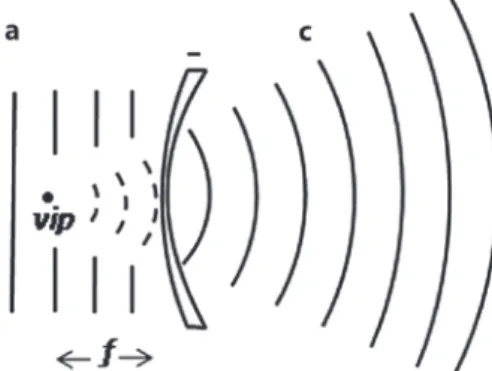
THEREALLIGHTSOURCESWe have stated that a refracted wavefront breaks its link to the original source and becomes associated with an image point. Ideally, this is true only when the refracted wave has a concave configuration. If it has a convex configuration, it continues to diverge infinitely and does not associate to any real image point. However, if the train of diverging waves is prolonged retrogradely it will produce the impression of emanating from a point located on the side of the incoming rays (Figure 4). This imaginary point is called the virtual image point.It cannot be projected on screens due to its absence of substance. Ho-wever, it can be visualized by the brain or a sensor, via interpolation of the data contained in the wave train. Virtual image points are typical of, but not exclusive to, negative lenses. With the appropriate optical system, it is also possible to create virtual object points.
For the easy identification of the virtual sources of light, the following rule may be used: virtual objects are generated by light that strikes the lens with the concave (converging) wavefront confi-guration; virtual images are created by light that exits the lens with the convex (diverging) wavefront configuration.
L
IGHTRAYSLight rays are imaginary lines that describe the path of light(26). They are helpful in finding the position, size, and orientation of images, even for complex optical systems. They are the basic tools of geo-metrical optics.
In an optically homogeneous medium, the rays are straight lines perpendicular to the wavefronts, which identify the direction of ener -gy flow. When the wavefront is not at infinity, the light rays (being normal to a spherical surface) bend and intersect each other at the
Figure 4. Backward projection of diverging waves in a concave lens. vip: virtual image
Visual optics under the wavefront perspective
270 Arq Bras Oftalmol. 2014;77(4):267-70
center of curvature of the sphere that defines its surface. In a sagittal plane containing the light source, these rays are arranged like the spokes of a wheel. If only one quadrant is considered, the rays con-figure an open fan whose apex is the light source (Figure 1B). When the wavefronts are flat, which is supposed to occur at infinity, the light rays form a bundle of parallel lines (Figure 1C). Thus, the enigma of the diverging rays that become parallel at infinity is due to the flattening of the wavefront. Because geometrical optics does not deal with wa-vefronts on a regular basis, it ends up causing this apparent enigma.
Another weakness of the bundle-of-rays approach is the difficulty it has in explaining vergence. The natural tendency is to represent a diverging bundle of rays as an open fan, with the vertex representing the object point and the rods representing the light rays (Figure 1B). So far, so good. The error occurs when one tries to guess the amount of vergence by the angle at the vertex of the fan. However, the angle is irrelevant here, since it is a distance-dependent variable. To find ver gence (in a vacuum or in air) all that is needed is the reciprocal of the distance, in meters, from the wavefront to its source. Since geometri-cal optics does not work regularly with wavefronts, it does not convey vergence conveniently. Even authorities in visual optics occasionally neglect this fact(27).
D
IRECTIONOFTHEPROPAGATIONOFLIGHTRegardless of the approach chosen to study the path of light, it is necessary to set up its direction of propagation. Once this is done, all distances are compared to it. There are different conventions for this goal(28-30) but the one we prefer is the following: light travels from left to right and distances are always measured from the curved surfaces (lens’ or waves) to the light sources (object points, image points, the center of curvature). Distances opposing the direction of light are negative; distances agreeing with it are positive. Vertical distances are positive above the optical axis and negative below it. This is the Cartesian Sign Convention, in analogy to Cartesian graphs. It should always be remembered that the very form of the written optical equations depend on the convention adopted.
F
INALREMARKSIn visual optics, light rays and wave trains are complementary. The use of one or the other depends on what information you want to put into evidence. If the primary goal is the position, size, and orientation of the image, the first approach (light rays) is preferable. However, if the objective is to deal with the accommodative effort of the eye, or with the vergences of lenses or waves, an approach using wave trains will be more profitable.
REFERENCES
1. Descartes’ Life and Work. In: Stanford Encyclopedia of Philosophy [Internet]. First published apr 9, 2001; substantive revision Sept 20 2010 [cited 2014 Jan 21]. Available from: http://plato.stanford.edu/entries/descartes-works/
2. Ribe NM. Cartesian optics and the mastery of nature. Isis. 1997;88(1):42-61. 3. McDonough J. Descartes’ “Dioptrics” and “Optics”. In: Larry N, ed. The Cambridge
Des cartes Lexicon [Internet]. Cambridge: Cambridge University Press; 2003 [cited
2013 Jun 21]. Available from: http://www.people.fas.harvard.edu/~jkmcdon/files/ papers/Descartes%20Dioptrics%20and%20Optics%20together%20as%20single%20 document.pdf
4. Szaflarski DM. How we see: the first steps of human vision [Internet]. [cited 2013 Jun 20]. Available from: http://www.accessexcellence.org/AE/AEC/CC/vision_ background.html
5. Hubel DH, Wiesel TN. Brain mechanism of vision. Scient Am. 1979;241(3):150-62. 6. Pettingrew JD. The neurophysiology of binocular vision. Scient Am. 1972;227:84-95. 7. My class site. How Is Light Produced? [Internet]. [cited 2013 June 13]. Available from:
http://myclass.peelschools.org/sec/10/50216/Lessons/Nelson%20Science%20 Perspectives%2010/05%20Optics/11.2.pdf
8. Johannes Kepler: his life, his laws and times. NASA [Internet]. [cited 2013 Dec 21]. Available from: http://kepler.nasa.gov/Mission/JohannesKepler/
9. Jaeger W. [Johannes Kepler’s contributions to ophthalmologic optics]. Klin Monbl Augenheilkd. 1986;188(2):163-6. German.
10. Greco V. The wave theory of light[Internet]. The victorian web: literature, history & culture in the age of Victoria. [cited 2013 Nov 21]. Available from: http://www. victorianweb.org/science/fresnel.html
11. Thomas Young (1773-1829) [internet]. UC Santa Barbara Geography [cited 2013 Jun 21]. Available from: http://www.geog.ucsb.edu/~jeff/115a/history/young.html 12. Lesson 58: Young´s double slite experiment. Thomas Young’s double slit ex peri ment
[internet]. [cited 2013 Jun 21]. Available from: http://www.studyphysics.ca/newnotes /20/unit04_light/chp1719_light/lesson58.htm
13. Schoolphysics. Theories of light [Internet].:Welcome Wave Properties (Huygens and Newton).[cited 2013 Jul 21]. Available from: http://www.schoolphysics.co.uk/age16-19/Wave%20properties/Wave%20properties/text/Theories_of_light/index.html 14. Christiaan Huygens [Internet]. In: Wikipedia, the free encyclopedia . [cited 2013 Jun
21]. Available from: http://en.wikipedia.org/wiki/Christiaan_Huygens
15.The Math Forum. Ask Dr. Math. Proof for the radius of curvature [Internet]. [cited2013 Jun 21]. Available from: http:mathforum.org/library/drmath/view/63864.html 16. Units of curvature and torsion [Internet]. [cited 2012 Jun 21]. Available from: https://
www.math.ku.edu/~jmartin/courses/math223-F10/units.pdf
17. Monoyer F. Sur l’introduction du système métrique dans le numérotage des verres de lunettes et sur le choix d’une unité de réfraction. Annales d’Oculistiques. 1872;68:101. 18. Wavelength and the Index of Refraction [Internet]. Rensselaer Polytechnic Institute
and DJ Wagner [cited 2013 Jun 21]. Available from: http://www.rpi.edu/dept/phys/ Dept2/APPhys1/optics/optics/node7.html
19. Wavelength, Frequency and Energy Calculations [Internet] . Mr Kent´s chemistry page [cited 2013 Jun 21]. Available from: http://www.kentchemistry.com/links/Atomic Structure/waveequations.htm
20. Pascal JI. Vergence related to the density of medium. In: Pascal JI. Selected studies in visual optics. St. Louis: C V Mosby; 1952. p.226-7.
21. Gaussian and Newtonian Thin Lens Formulas[Internet]. [cited 2013 Nov 24]. Available from: http://www.photonics.com/EDU/Handbook.aspx?AID=25475.
22. Bühler WK. Gauss: a biographical study. Berlin: Springer-Verlag; 1981.
23. Carl Friedrich Gauss [Internet]. In: Complete Dictionary of Scientific Biography. [cited 2013 Jul 27]. Available from: http://www.encyclopedia.com/topic/Carl_Friedrich_ Gauss.aspx
24. Physics 111: Elementary physic: thin lenses [Internet]. [cited 2013 Jun 21]. Available from: www.physics.louisville.edu/jcmorrison/111/LabE_ThinLenses.doc
25. Rubin M. Optics for clinicians. 2nd ed. Gainesville, FL: TRIAD Scientific; 1977.
26. Walker BH. Basic concepts of light. In: Walker BH. Optic Engineering Fundamentals. Bellingham: SPIE Press; 1998. p.35-42.
27. Pascal JI. Vergence related to the size of aperture. In: Pascal JI. Selected studies in visual optics. ST. Louis: CV Mosby; 1952. p.141.
28. The longitudinal lens formula and sign conventions [Internet]. Nuffield Foundation [cited 2013 Jun 21]. Available from: http://www.nuffieldfoundation.org/practical-phys ics/longitudinal-lens-formula-and-sign-conventions
29. Rojas R. Graphical synthesis of sign conventions in geometrical optics. Eur J Phys. 2013;34(4):1089-93.