Abstract
A series of analyses are carried out to predict the structural crash-worthiness of a ship during a collision. The numerical configuration is verified by structural simulations based on a laboratory experi-ment wherein a penetration test is considered as the experiexperi-mental reference. Comparative observations of structural behaviour are care-fully conducted to ensure the reliability of the present method for conducting large-scale collisions. At this stage, the proper procedure and configuration for structural calculations subject to accidental loads are determined. The second stage addresses the calculations for various side collision scenarios. The simulations consider a double hull Ro-Ro passenger ship being struck at various locations, and the overall behaviour of the side hull along the longitudinal axis is ob-served. The main study considers the target location and striking speed to obtain adequate data related to crashworthiness criteria, i.e. the internal energy and extent of damage. Finally, the criteria of various scenarios are summarized. Further calculations comparing the results with a safety factor are presented together with a consid-eration of structural behaviour to estimate the safety limit within the confines of strait territory.
Keywords
Collision phenomenon, penetration test, target location, striking ve-locity, crashworthiness criteria, speed limit
Analysis of Structural Crashworthiness and Estimating Safety
Limit Accounting for Ship Collisions on Strait Territory
1 INTRODUCTION
Currently, there is growing public demand for reductions in the risk to human lives and pollution at sea, as well as to minimize the damage caused by ship accidents resulting from impacts or accidental loads, namely collisions. Shipping safety and marine pollution are inextricably linked, and the protec-tion of the environment from major disasters caused by ships sinking is rather complex. Efforts to protect the safety of ships and the sea environment are generally divided into two classes: active and
Aditya Rio Prabowo a Dong Myung Bae b Joung Hyung Cho a Jung Min Sohn b
a Interdisciplinary Program of Marine
Convergence Design, Pukyong National University, South Korea
b Department of NavalArchitecture and
Marine Systems Engineering, Pukyong National University, South Korea [[email protected]]
http://dx.doi.org/10.1590/1679-78253942
passive methods (Törnqvist, 2003). Active methods assume that navigation equipment, crew training, and traffic control systems can prevent accidents from taking place, whereas passive methods attempt to minimize the consequences by, for instance, enhancing the crashworthiness of hull structures or improving rescue operations. Several studies have been conducted on decision making and detection methods related to collisions as an effort to improve ship safety (Zhang et al., 2015a, b). Collisions between ships and collision accidents with bridges have also been considered (Perera and Soares, 2015). Ship safety following a collision accident event is bound to the collision phenomenon according to the external dynamics and internal mechanics (Minorsky, 1958). The external dynamics concern the global motions of the ship during the collision event, whereas the internal mechanics focus on the volume of the damaged material. In ship-to-ship collision events, the impact energy is mainly absorbed by large structural deformations on the struck ship. If the outer shell of the struck ship resists the penetration of the striking ship without the inner shell rupturing, damage to passenger cargo can be minimized in a Ro-Ro passenger ship and oil spillage and flooding can be avoided in a tanker carrier. This concept has been applied in several pioneering studies, namely those of Lützen (2001), Bae et al. (2016a, b), and Prabowo (2016a, b). Furthermore, the influence of the external dynamics on ship safety following a collision accident is very significant. The international certification institution and classification societies Det Norske Veritas (from Norway) and Germanischer Lloyd (from Germany), collectively known as DNV–GL, introduced the critical collision speed into ship collision analysis (DNV–GL, 2013). The importance of this factor was strengthened by the collision phenomenon theory of Minorsky (1958), who found that ship speed is included in the external dynamics and contributes significantly to the collision calculation results.
This study is a continuation of the assessment of structural behaviour in ship collisions by Bae (2016a) and Prabowo (2017a-c) which expands into observations of the damage tendency and speed analysis in certain regions. The location and speed are considered as the main parameters in order to evaluate crashworthiness criteria in the event of a collision between two ships. The extent of the damage to the side structure after the collision process is summarized into statistical data that can be used to estimate the critical scenario. Finally, an alternative procedure for collision analysis is presented together with predictions of the double hull condition after impact.
2 LITERATURE REVIEW
2.1 Fundamental Basis and Pioneer Work
To consider the external dynamics during a collision process between two objects, the defining pa-rameters must be determined to enable realistic research scenarios to be constructed from the actual situation. This step is applied using a simplified concept, as given in Fig. 1, which is built according to the Cartesian coordinate system. The nomenclature includes: X = the longitudinal (x) axis of Ship A, Y = the transverse (y) axis of Ship A, 1 = the 1-axis of Ship B, 2 = the 2-axis of Ship B, c = the
contact point between Ship A and Ship B, = the angle between the X-axis and the η-axis, = the
angle between the X-axis and the 1-axis, ξ = the normal direction to the impact surface, Fξ= the
normal force to the impact surface, η = the tangential direction to the impact surface, Fη= the
during the collision process. According to Newton’s Third Law, for every action, there is an equal and opposite reaction.
Figure 1: The coordinate system used for analysis ship-ship collision (Zhang, 1999).
This means that in every interaction, there is a pair of forces acting on the two interacting objects. The size of the forces on the first object equals the size of the forces on the second object. When
external dynamics control the collision process, the reaction on the ships structure is referred to as
the internal mechanics of ship collision. Internal mechanics are the effect of the external dynamics and some main parameters from both the struck and striking ships. The main reaction that will occur is absolute damage to the ships’ structure. In a collision event between a rigid striking bow and a deformable struck ship, the side structure of the struck ship will experience deformation, destruction, or penetration. The deformation and destruction of the struck ship may include tension of the shell plating, crushing of the transverse frames and longitudinal stringer, and crushing of the bottom of the decks. The resistance of each component can be calculated by summarising all resistances, includ-ing the total resistance and dissipated energy. An initial deformation of a side shell platinclud-ing usinclud-ing this analytical illustration is presented in Fig. 2. The case where a striking bow impacts the centre of a shell plate with boundaries at the adjacent decks and transverse frame is considered for further
cal-culation. The distance between the two decks is 2b. The illustration also implicitly states that the
rupture and failure contours during and after collision are highly influenced by the design criteria of the ship, especially the width of the double hull.
2.2 Design Criteria for Ship Structure
The structural design of ships carrying dangerous goods or passengers must satisfy the Oil Pollution Act (OPA) of 1990 and equivalent International Maritime Organization (IMO) requirements. Alt-hough passenger ships do not carry dangerous goods or pollutants as their main cargo, human lives are unacceptable casualties in any collision accident. The primary safety requirements are to arrange a double bottom of a required minimum height and double sides of a required minimum width. In this context, the height requirement for the double bottom is essential in grounding accidents. Nev-ertheless, accounting for side collisions, the required width of the double sides will be reviewed. OPA and IMO require that the minimum size of the wing ballast tank and double bottom or void space is not less than the value given by Equation (1) (Rigo and Rizzuto, 2003) and Equation (2) (IMO, 1996).
w =
20
,
000
5
.
0
DWT
(m) or w = 2.0 m, whichever is the lesser.The minimum value of w = 1.0 m.
(1)
h = B / 15 (m) or h = 2.0 m, whichever is the lesser.
The minimum value of h = 1.0 m. (2)
F x hc x ρc x g + p ≤ dn x ρs x g (3)
where w is the width of the double side, DWT is the deadweight of the ship, h is the height of the double bottom, B is the breadth of the ship, f is safety factor, hcis the height of cargo in contact with
the bottom shell plating, ρc is the maximum cargo density, g is the standard acceleration of gravity,
p is the maximum set pressure above atmospheric pressure (gauge pressure) of pressure/vacuum valve
provided for the cargo tank, dn is the minimum operating draught under any expected loading
condi-tion and ρs is the density of seawater.
The spaces required by this regulation may be dispensed with, provided that the design of the tanker is such that the cargo and vapour pressure exerted on the bottom shell plating forming a single boundary between the cargo and the sea does not exceed the external hydrostatic water pressure, as expressed by Equation (3). The accidental limit state of this paper is determined by the integrity and performance of the struck ship’s structure. The structural design criteria relate the structural integrity to performance. For ship collisions, the design criteria are based on limiting the accidental conse-quences of structural damage and environmental pollution, as well as ensuring that the main safety functions of the ship’s structure are not impaired to a significant extent during any accidental event or within a certain time period thereafter. The structural performance of a ship against collision or
impact load can be measured by the energy absorption capability and maximum penetration in an
accident. According to previous work (Wang et al., 2001), the design acceptance criteria may be based
on the minimum distance of cargo containment from the outer shell and ship speed above which a
The influence of speed is vital in the event of collisions between ships and in collisions between a ship and a bridge. A survey of international bridge projects (Pedersen et al., 1998; ISSC, 2006) con-cluded that a risk analysis required the selection of a design collision scenario such as ship speed to measure collision severity. According to this conclusion, the cost of safety measures become important when control options are exercised to reduce the risks associated with collisions and groundings. Ship speed and other factors, e.g. traffic lanes, are also defined as ship operator risk options and societal responsibilities. In terms of speed, the ship’s design can be assessed by calculating the probability distributions of kinetic energy when sailing with a known displacement and speed, and the hull’s crashworthiness is estimated for a given area of navigation (ISSC, 2006). These references indicate that ship speed is closely related with damage level in the collision process, and so a proper assessment is required to ensure the safety of ships passing through certain traffic lanes. From another perspec-tive, the safety of traffic lanes is the responsibility of society, and so ship speeds should be regulated. The influence and effect of safe ship speeds in certain regions should therefore be assessed and deter-mined, especially in terms of collisions and other impact-accident phenomena.
3 FUNDAMENTAL BASIS OF FAILURE FORMULATION
3.1 Setting and Configuration
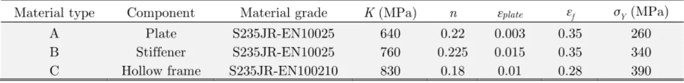
An experimental study by Alsos and Amdahl (2009), which deals with hull damage in ships, is re-conducted as a verification of the numerical methodology. Although their experiment addressed grounding impact, it is considered good enough to use as a reference for ship collisions and ice-structure interaction. The concept of the experiment involves the forcing of an indenter in a stiffened plate model. The plate target consists of three components, namely the plate, stiffener, and a hollow frame; the properties of these components are described in Table 1. During the experiment, the in-denter penetrates the plate to a depth of approximately 0.25 m while the plate is supported by the hollow frame. This experiment is re-performed using the finite element codes of ANSYS LS-DYNA (ANSYS, 2017). The idealized model of the stiffened plate is built and implemented using fully inte-grated Belytschko–Tsay shell elements. The indenter is set to move to the centre of the plate with a constant velocity of 0.6 m/s. The mesh size of each component of the stiffened plate is successively set to 10, 15, and 25 mm. The results in terms of the crushing force and extent of damage will be compared with the experimental results.
Material type Component Material grade K (MPa) n εplate εf σY (MPa)
A Plate S235JR-EN10025 640 0.22 0.003 0.35 260
B Stiffener S235JR-EN10025 760 0.225 0.015 0.35 340
C Hollow frame S235JR-EN100210 830 0.18 0.01 0.28 390
Table 1: Material properties for the stiffened plate (Alsos and Amdahl, 2009).
3.2 Results
stress concentration on the lower part (denoted by red in Fig. 3b) which caused folding in this com-ponent along the plate.
(a) (b)
Figure 3: Extent of damage on the stiffened plate. Folded stiffener in (a) actual experiment (Alsos and Amdahl, 2009) is found match with extreme stress contour as shown in (b) numerical calculation.
(a) (b)
Figure 4: Structural response in crushing process of the stiffened plate: (a) force and (b) energy.
The numerical study gives satisfactory results when compared with the actual experiment. The stiffener experienced folding along the plate due to continuous penetration by the indenter. The next comparison examines the force fluctuation during penetration. The results from the actual experiment are presented together with the numerical analysis given by varying the mesh size of the model. The force fluctuations in Fig. 4a indicate that the actual experiment and numerical study have a similar incremental tendency, although there are some differences in the magnitude and position of the peak
point. The element length (le) of 15 mm produces good similarity with the actual experiment. The
crashworthi-ness criteria, i.e. extent of damage, force, and energy, show that the present methodology for con-ducting numerical analysis is satisfactory, and can therefore be implemented in further collision anal-ysis.
4 PREPARATION AND CONFIGURATION FOR THE FINITE ELEMENT SIMULATION
4.1 Engineering Model
When a collision takes place between two ships, we denote the struck ship (Fig. 5a), in which the
target location is determined, and the striking ship (Fig. 5b), whose bow penetrates the designated
target points on the struck ship. The main dimensions for these ships are presented in Table 2. The struck ship is augmented by deformable characteristic, and the striking ship is idealized as a rigid body. The ships are modelled and discretized with fully integrated Belytschko–Tsay shell elements. The mesh size should be small enough to capture the major deformation contour, but sufficiently large to ensure a practical calculation time. Ratios of element-length-to-thickness of between 5–10 (Törnqvist and Simonsen, 2004) are considered in this study. When a collision takes place, the two ships interact. Therefore, a general steel–steel friction coefficient (μ) is implemented in describing the contact.
(a) (b)
Figure 5: Models of the involved ships for collision analysis [10]: (a) the struck ship (fore end) and (b) the striking ship.
Dimension Struck ship Striking ship
Deadweight (ton) 683 t 7906 t
Length over all (m) 85.92 m 144.50 m
Length between perpendicular (m) 78.00 m 19.80 m
Breadth moulded (m) 15.00 m 5.60 m
Depth (m) 10.40 m 10.20 m
Table 2: Main dimensions of the involved ships.
that shares fundamental properties with the deformable model. The properties of both material mod-els are presented in Table 3. In the collision process, the displacement on the struck ship is set to be fixed at the centreline. The fixation is applied at the end of the model on the transverse frame. At this location, the axial displacement of the shell plating is restrained.
Mechanical properties Deformable model Rigid body
Density (kg/m3) 7850 7850
Young's modulus (Pa) 2.1 x 10¹¹ 2.1 x 10¹¹
Poisson’s ratio 0.30 0.30
Yield stress (Pa) 4.4 x 10⁸ -
Failure strain 0.20 -
Table 3: Mechanical properties for deformable and rigid bodies.
4.2 Scenario Arrangement and Defined Collision Model
In the present study, the target location and speed of the striking ship are taken as the main param-eters. The objectives of the main study are as follows: first, to produce reference data from a series of collision analyses, and second, to analyse the resulting data and conclude a speed limit for both ships according to the operational territory. To achieve these purposes, a series of analyses is carried out using more than 30 collision scenarios. To manage the large number of scenarios, the present work is divided into two phases, namely observation on crashworthiness criteria and a discussion of speed limits. All results are used in formulating our conclusions and recommendations in the final part of this paper.
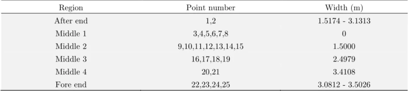
The target location is determined along the longitudinal axis of the ship’s hull. The coordinate of the target point in each region is the same in terms of the vertical axis: 10.25 m from the baseline. As for the longitudinal axis, the distance between target points is also the same, and 25 target points are deployed to define 25 collision scenarios. The target location is illustrated in Fig. 6. During the collision, an approximate speed of 12 kts (6 m/s) is used. To assess the speed of the striking ship, four regions of the struck ship are classified (see Table 4). In each region, four applied speeds for the striking ship are considered (from 5–20 kts (approx. 2.5–10 m/s) in increments of 5 kts) to observe the capability and behaviour of the struck ship’s side structure during impact.
Region Point number Width (m)
After end 1,2 1.5174 - 3.1313
Middle 1 3,4,5,6,7,8 0
Middle 2 9,10,11,12,13,14,15 1.5000
Middle 3 16,17,18,19 2.4979
Middle 4 20,21 3.4108
Fore end 22,23,24,25 3.0812 - 3.5026
(a)
(b)
Figure 6: Illustration of the defined collision scenarios for each study: (a) target location and (b) striking speed.
5 RESULTS AND DISCUSSION
This section presents the analysis results of a finite element simulation. The presentation of results is divided into three main sub-sections, namely: collision location, striking ship speed, and overall dis-cussion on speed limits.
5.1 Phase 1: Target Location
The analysis in this section was conducted to observe the effect of collision load on the ship’s hull in
terms of the longitudinal direction (or x-axis, according to the Cartesian coordinate system). As
mentioned in the previous section, 25 target points were assigned on the side hull of the struck ship. The different structural preferences in size and arrangement produced nonlinearities in the calculation results.
which matches the characteristics of the side structure. The internal energy represents the amount of energy needed to plastically deform the entities involved in an impact. In extreme situations, such as collisions, grounding, and explosions, the energy is not only used to plastically deform the target structure, but also to destroy it. As stated above, this tendency satisfies the correlation between the energy and structural arrangement. The energy in the middle regions has a larger magnitude than at the aft and fore ends, which indicates that the middle regions are harder to destroy during a collision.
Location no. xcoordinate (m) Internal energy (MJ) Damage extent Tearing [outer shell]
Disp. (m)
Tearing [inner shell]
Disp. (m) Length (m) Width (m) Length (m) Width (m)
1 -39 8.559 3.345 1.350 2.249 1.687 0.389 1.749
2 -35.75 9.120 4.207 1.932 2.249 0.000 0.000 0.500
3 -32.5 5.958 4.091 2.836 2.249 0.000 0.000 0.000
4 -29.25 7.254 3.725 2.481 2.249 0.000 0.000 0.000
5 -26 7.317 3.234 0.501 1.999 0.000 0.000 0.000
6 -22.75 4.258 1.680 0.408 2.249 0.000 0.000 0.000
7 -19.5 9.172 3.092 0.370 1.999 0.000 0.000 0.000
8 -16.25 9.202 3.346 2.429 1.999 0.000 0.000 0.000
9 -13 9.335 3.227 2.425 1.999 0.000 0.000 0.750
10 -9.75 10.047 3.594 2.474 1.999 0.851 0.094 0.750
11 -6.5 9.887 3.592 2.335 1.999 1.091 0.093 0.750
12 -3.25 9.627 3.839 2.483 1.999 0.735 0.102 0.500
13 0 9.628 4.076 2.486 1.999 0.850 0.093 0.500
14 3.25 9.677 2.992 2.687 1.999 0.000 0.000 0.500
15 6.5 9.794 2.718 0.556 1.749 0.000 0.000 0.750
16 9.75 8.599 4.802 1.215 1.999 0.000 0.000 0.750
17 13 9.889 5.731 1.223 1.866 0.000 0.000 0.746
18 16.25 9.498 5.025 1.159 1.622 0.000 0.000 0.541
19 19.5 10.349 4.536 1.661 1.499 0.000 0.000 0.500
20 22.75 10.894 4.746 1.269 1.399 0.000 0.000 0.700
21 26 8.613 5.204 1.721 1.394 0.000 0.000 0.279
22 29.25 6.833 3.760 2.503 1.749 0.000 0.000 0.250
23 32.5 7.392 2.732 3.389 1.749 0.000 0.000 0.250
24 35.75 7.702 3.014 3.245 1.749 0.000 0.000 0.500
25 39 4.537 2.213 0.734 1.749 0.000 0.000 0.250
Mean 8.526 3.701 1.835 1.910 0.209 0.031 0.521
Standard error 0.346 0.191 0.182 0.051 0.091 0.017 0.074
Standard deviation 1.729 0.957 0.909 0.255 0.453 0.083 0.372
Sample variation 2.991 0.916 0.826 0.065 0.206 0.007 0.139
Confidence level (95%) 0.678 0.375 0.356 0.100 0.178 0.032 0.146
Figure 7: Internal energy characteristic along ship hull in longitudinal direction.
Figure 8: Behavior of the internal energy during penetration per target location.
aft and fore ends. At the aft end, two target points produced remarkable differences, with point 1 displaying a tear in both shells and point 2 only suffering some displacement of the inner shell. This result is influenced by the arrangement of the side structure at the aft end, where there is a region without a double hull (denoted as the middle 1). Point 2 is closer to the middle 1 and suffered only minor damage to the inner shell after the collision process. In the middle regions, the collision pro-duced relatively stable results in terms of the energy. Verification of the energy summary per target is presented in Fig. 8, which shows that the middle structure has a more uniform response than other regions. The tendency of the force fluctuation is shown in Fig. 9. The crushing force is defined as the amount of force experienced by the target structure during penetration by the striking ship. Besides its similarity, the average crushing force of the middle 2 is higher than in other regions because, in this location, the double hull width is the lowest (1.5 m). During penetration, the striking ship pushes back the inner shell. Therefore, the force graph of this region shows an incremental tendency until the end of the collision. This phenomenon validates the global result in the location study (Table 5), which indicates that the inner shell in this region got displaced in range 0.5–0.75 m.
Figure 9: Fluctuation of the crushing force during side collisions.
inner shell in this region. If the outer shell is breached by any striking object, the extent of damage to passenger cargo near this area can be immense. The damage to the inner shell was dominated by displacement, while tearing was also found at locations 10–13. In this area, direct contact between the cargo and the striking ship is inevitable. After collision, the displaced inner shell is likely to deliver a vital blow to any cargo. Another critical situation is expected to occur along the middle region (locations 7–20), where the highest deformation is 0.75 m. Despite this result, the global structure reaction along the side hull is good during a collision with a striking object with speed 6 m/s, as no sporadic fatal damage occurred on the inner shell. The tendency for tearing damage on the inner shell only occurred in five locations, with tear lengths greater than 1 m in only two locations or 8% of total scenarios. It can be initially concluded that the possibility of fatal damage during collision with a striking speed of 6 m/s along the side shell is less than 10%, with the highest likelihood of tearing and displacement on the edge of the aft region where passenger cargo is unlikely to be placed.
The interaction between damage extent on the outer and inner shells is presented in Fig. 10. This shows that damage to the outer shell tends to reduce from aft to fore end as the width between the outer and inner shells increases. However, the tendency for damage to the inner shell increases at the middle region and reduces toward the aft and fore end regions. This result matches the safety char-acteristic of the fore end, where the double hull size is the widest among all regions, and no displace-ment of the inner wall was observed during and after the collision process.
Figure 10: Interaction of element displacement at the both of shells.
5.2 Phase 2: Striking Speed
Figure 11: Tendency of the structural displacement on double hull structure against several striking speeds.
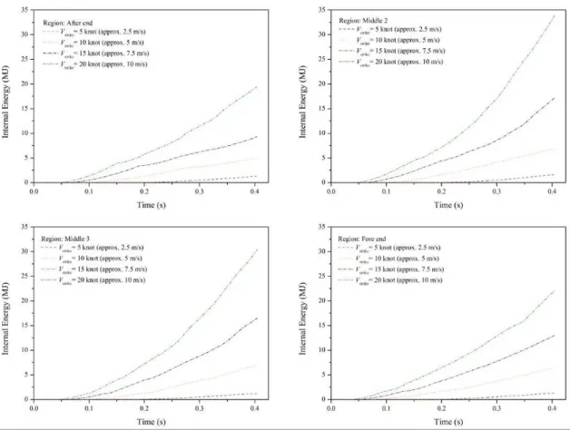
The lower extent on the inner shell indicates that less damage is experienced by this component, as the major damage has been absorbed by the outer shell. In assessing the displacement to the inner shell, a 15-kts collision speed (approx. 7.72 m/s) produces a displacement of 0.5 m. This value can be used to make a rough estimation that the ship’s cargo may be deformed or displaced from its initial location. The results presented in Fig. 9 describe the extent of the damage to the fore end region, which has the widest double hull space of the struck ship. The displacement of 0.5 m is already considered critical in this study, as this collision model may occur to other regions that have lower double hull spaces than the fore end. Beyond this point, side collision with a striking ship moving at 20 kts (approx. 10 m/s) results in immense damage, with the outer shell suffering displacement of over 4 m and the inner shell being displaced more than 1 m. Confirmation of the energy characteristics at each striking speed (Fig. 10) show the good correlation between higher energy being produced at higher collision speeds.
Figure 13: Increment progress of the internal energy in collision process.
to be the main cause for this tendency. The pattern of webbing and main frame in the double hull structure is considered to be non-uniform.
Figure 14: Fluctuation of the crushing force for each region by different striking speeds.
5.3 Phase 3: Overall Discussion of the Present Results and Existing Safety Factors
This study has assessed several crashworthiness criteria during ship collisions. The scenarios refer to a collision incident on the Sunda strait territory approximately three years ago. In this instance, a T-collision occurred between two ships, producing remarkable structural damage on the side structure of the struck ship, i.e. passenger ship (details can be obtained from Bae et al., 2016b and Prabowo et al., 2017a). This strait is a major voyage route in the southern seas. The main destinations along this route are Fremantle (Australia), Jakarta (Indonesia), and Singapore. The Sunda strait connects two main islands of Indonesia, namely Java and Sumatra. Ro-Ro passenger ships dominate the route from Merak to Bakauheni, which runs east-to-west. These routes inevitably lead to crossing situations, which may result in impact incidents, i.e. side collisions. The high possibility of crossing situations causing collisions is detailed in the Collision Regulation (COLREGS) (IMO, 1972). Considering the data produced by our numerical analysis, we estimate a speed limit for ships passing through the Sunda strait. Such regulations can be implemented by Indonesia, as the strait is in an exclusive economic zone (EEZ), which allows a country to conserve and manage natural resources, such as by protecting the water environment from pollution due to various causes, e.g. collision incidents (Na-tional Government, 1983; Patuzi, 2015; IMO, 2008).
Based on the results in the preceding sub-sections, speeds of 0–5 kts tend not to cause any dis-placement of the inner shell after collision. The disdis-placement of the outer shell is less than 0.6 m at these speeds. During a collision in this speed range, damage to the middle 1 region, which does not have an inner shell, is still considered safe, as the displacement in the outer shell is not remarkable. At 10 kts, the outer shell is displaced by more than 1.5 m, but the inner shell exhibits a similar displacement to that at lower collisions speeds. Confirmation of the internal energy shows a reasonable pattern, as the energy in each region is not scattered significantly. The location study in sub-section 5.1 found large-scale damage at only three locations along the side hull. The safe condition is main-tained when the striking ship is moving at 12 kts. However, above 15 kts, both the outer and inner shells suffer large displacements and are subjected to high energies. The structural crashworthiness at these two speeds is considered remarkable, and such collisions should be prevented. To compare the results with a safety estimation, the recommended safety factor for impact load (Rosato and Rosato, 2003) is applied. The safety factor is a ratio between the yield state and the working stress. The yield state is considered to be the failure state, which occurs during the 15-kts collision, and the working state is determined as the 5-kts collision (i.e. no major damage to either shell after collision). To expand our observations on this factor, the 10-kts collision is included for comparison. The internal energy represents the capability of the structure to resist penetration perpendicular to the experienced stress/force (Bae et al., 2016a, b; Prabowo et al., 2016a, b; 2017a-d). Therefore, the magnitude of the internal energy is used to assess the safety condition of the structures against side collision loads. The results of the striking speed and comparison with the safety factor are presented in Tables 6 and 7, respectively. The results for the middle 2 and 3 regions are calculated, as these regions are located in the middle ship area which experiences high bending loads and are stronger than the middle 1 and 4 locations, which are near the aft and fore end regions.
not satisfy the collision load characteristics over short periods of time. This comparison indicates that only the 5-kts striking speed adheres to the proposed factors. However, it is not feasible to apply this speed limit in all conditions when a ship uses the Sunda strait. The 10-kts speed satisfies the factor representing the characteristic of collision load (static short-term load), and can therefore be used as the upper speed limit when crossing situations are expected to occur. Serious attention should be given to navigational instruments and the role of the communication tower in both ports to observe voyage conditions on the strait. During certain dangerous situations, e.g. bad visibility due to fog and limited manoeuvrability because of the local topology, the lower speed limit of 5 kts is strongly encouraged. This should be implemented by ship crew, port communication tower staff at the Merak and Bakuheni ports, and weather/meteorology/geophysics monitoring staff in observing and moni-toring voyage activities on the Sunda strait. In forming considerations based on absolute safety, the safety of the limiting design should be calculated using a safety factor. There are no hard and fast rules in setting a safety factor. As the occurrence of ship collisions is very nonlinear, the most basic consideration in applying a safety factor is the consequence of failure. There are five additional con-ditions to be taken into consideration: (1) variation in structural arrangement along the ship’s hull; (2) variation in double hull performance; (3) effect of stating material strength properties; (4) type of loading (static, dynamic, etc.); and (5) overall concern for human safety.
Speed (kt) Internal energy (MJ)
After end Middle 2 Middle 3 Fore end
5 1.31 1.63 1.21 1.31
10 6.39 6.89 7.04 4.92
15 13.02 17.18 16.54 9.34
20 22.11 33.88 30.40 19.49
Table 6: The internal energy for different regions subjected to various striking speed.
Location
Calculated factor Load type
5 kts 10 kts
Static
short-term
Static
long-term Repeated
Variable
change Fatigue Impact
After end 10 2
1 - 2.5 2 - 5 5 - 15 4 - 10 5 - 10 10 - 15
Middle 2 11 2
Middle 3 14 2
Fore end 7 2
Table 7: Calculation of safety factor and comparison with the proposed factor of (Rosato and Rosato, 2003).
6 CONCLUSIONS
phase in which we obtained information regarding the structural response at different striking speeds. The magnitude of internal energy and extent of damage were calculated and assessed as representative of crashworthiness criteria. After conducting these two phases, the safety factor of the structure was calculated. As part of an overall discussion to determine a speed limit, the shipping route, collision regulations, international maritime territory classification, and existing safety factors must be
consid-ered. There are two main remarks about this study. First, the load type was considered in assessing
which impact load safety factor was used for the main comparison. As an additional parameter, the collision characteristic was also applied, with the static short-term load safety factor chosen. The impact load was used to determine the lower limit, whereas the short-term load was applied to assess the upper limit. The assumptions used in calculating the safety factor can be substituted for other parameters related to the applied stress/force and the internal energy. However, the substituted pa-rameters should be closely related both mathematically and physically, e.g., energy and force are
related structural responses. Second, based on the analysis and assessment of the crashworthiness
criteria in terms of the internal energy and extent of damage, it can be concluded that the recom-mended speed for the strait considered in this study is 5–10 kts when a crossing situation is expected to occur. Higher speeds can be used during clear conditions (good visibility and manoeuvrability) and when no crossing situations will take place. For crossing situations in clear conditions, an operational speed limit of 10 kts can be applied. However, in bad weather when vision and manoeuvrability are restricted, the speed limit should be reduced to 5 kts.
In the case of collisions involving significant nonlinearities, this study can be considered as an adequate reference for other impact analyses and calculations. A further collision analysis using a probabilistic-based method is highly encouraged by the authors. The assessment subject can be ex-panded to port regions to estimate the speed limit for ships entering a port. Actual maritime incidents should be used as a reference in early reviews during future assessments.
Acknowledgement
The authors gratefully acknowledge financial support from the BK21 plus MADEC Human Resource Development Group for supporting the current work in the paper writing stage. This work was sup-ported by Research Grant of Pukyong National University (2016 Year).
References
Alsos, H.S., Amdahl, J., (2009). On the resistance to penetration of stiffened plates, Part I – Experiments. International Journal of Impact Engineering 36: 799-807.
ANSYS, (2017). ANSYS LS-DYNA user’s guide. ANSYS. Inc., Pennsylvania, US.
Bae, D.M., Prabowo, A.R., Cao, B., Sohn, J.M., Zakki, A.F., Wang, Q., (2016a). Numerical simulation for the collision between side structure and level ice in event of side impact scenario. Latin American Journal of Solids and Structures 13: 2991-3004.
Bae, D.M., Prabowo, A.R., Cao, B., Zakki, A.F., Haryadi, G.D., (2016b). Study on collision between two ships using selected parameters in collision simulation. Journal of Marine Science and Application 15: 63-72.
IMO, (1972). International regulations for preventing collision at sea (as amended by Resolution A464(XII), A626(15), A678(16) and A736(18)). International Maritime Organization, London, UK.
IMO, (1996). Marine Pollution: Annex I – Regulation for the prevention of pollution by oil, Chapter 4 - Part A, International Maritime Organization, London, UK.
IMO, (2008). Report of the maritime safety committee on its eighty-fourth session (MSC 84/24Add.1 - Annex 1). International Maritime Organization, London, UK.
ISSC, (2006). Collision and grounding. In the 16th International Ship and Offshore Structures Congress, Southampton, UK.
Lützen, M., (2001). Ship collision damage. Technical University of Denmark, Lyngby, Denmark.
Minorsky, V.U., (1958). An analysis of ship collision with reference to protection of nuclear power ships. Journal of Ship Research 3: 1-4.
National Government, (1983). Indonesian Economic Exclusive Zone (UU 5/1983). Government of Indonesia: Jakarta, Indonesia.
Patuzi, D., (2015). The concept of the economic exclusive zone. Academic Journal of Bussiness, Administration, Law and Social Science 1: 149-159.
Pedersen, P.T., Gluver, H., Olsen, D., (1998). Proceedings of the International Symposium on Advances in Ship Col-lision Analysis, Copenhagen, Denmark, Ed., A.A. Balkema, Rotterdam, the Netherlands.
Perera, L.P., Soares, C.G., (2015). Collision risk detection and quantification in ship navigation with integrated bridge systems. Ocean Engineering 109: 344-354.
Prabowo, A.R., Bae, D.M., Sohn, J.M., Cao, B., (2016b). Energy behavior on side structure in event of ship collision subjected to external parameters. Heliyon 2: e00192.
Prabowo, A.R., Bae, D.M., Sohn, J.M., Zakki, A.F, (2016a). Evaluating the parameter influence in the event of a ship collision based on the finite element method approach. International Journal of Technology 4: 592-602.
Prabowo, A.R., Bae, D.M., Sohn, J.M., Zakki, A.F., Cao, B., (2017b). Rapid prediction of damage on a struck ship accounting for side impact scenario models. Open Engineering 7: 91-99.
Prabowo, A.R., Bae, D.M., Sohn, J.M., Zakki, A.F., Cao, B., Cho, J.H., (2017c). Effects of the rebounding of a striking ship on structural crashworthiness during ship-ship collision. Thin-Walled Structures 115: 225-239.
Prabowo, A.R., Bae, D.M., Sohn, J.M., Zakki, A.F., Cao, B., Wang, Q., (2017a). Analysis of structural behavior during collision event accounting for bow and side structure interaction. Theoretical and Applied Mechanics Letters 7: 6-12. Rigo, P., Rizzuto, E., (2003). Analysis and design of ship structure (A Part of the Ship Design and Construction written by an International Group of Authorities Volume 1 and 2). Society of Naval Architects and Marine Engineers, New Jersey, US.
Rosato, D.V., Rosato, D.V., (2003). Plastic engineered product design. Elsevier: Oxford, UK.
Törnqvist, R., (2003). Design of crashworthy ship structures. Technical University of Denmark, Lyngby, Denmark. Törnqvist, R., Simonsen, B.C., (2004). Safety and structural crashworthiness of ship structures; Modelling tools and application in design. In the 3rd International Conference on Collision and Grounding of Ships, Izu, Japan.
Wang, G., Spencer, J., Chen, Y., (2001). Assessment of a ship’s performance in accidents. In the 2nd International Conference on Collision and Grounding of Ships, Copenhagen, Denmark.
Zhang, J., Zhang, D., Yan, X., Haugen, S., Soares, C.G., (2015a). A distributed anti-collision decision support formu-lation in multi-ship encounter situations under COLREGs. Ocean Engineering 105: 336-348.
Zhang, S., (1999). The mechanics of ship collisions. Technical University of Denmark, Lyngby, Denmark.