Comparison between the Use of the Middle Ring and/or Skewed Bars
in Induction Motor Rotor
Marcelo Dias da Silva
(1), Daniel Schmitz
(2), Carlos Manuel de Araújo Sá
(3), Bruno
Baptista
(1), Sebastião Lauro Nau
(2)(1)
WEGeuro Indústria Eléctrica,
(2)WEG Equipamentos Elétricos,
(3)Faculdade de
Engenharia da Universidade do Porto
Abstract
The paper compares several results of laboratory tests of induction motor rotors with different squirrel-cage characteristics, like skewed bars and the use of a middle ring. It is intended to make comparisons between rotors that do not use any of these characteristics and rotors that use only one or both of them. The comparisons are based on laboratory tests, namely: performance test in steady state, torque-speed curve and noise test at rated load. The results show that either skewed bars or middle ring have a relevant impact on the overall performance of the motor. Therefore, depending on the application of the motor, the adoption of one or both the characteristics can help the motor to meet the performance requirements.
1. Introduction
Induction motors have been subject to continuous improvement since their invention, more than one hundred years ago. The gains have been achieved by using better electromagnetic and insulating materials and the development of new designs for many parts of the machine, including the rotor bars and end rings.
Several designs have emerged regarding the squirrel-cage of the rotor, most of them focused on skewed bars or on the use of a middle ring. These solutions brought improvements to some performance characteristics of induction motors [1] – [4]. For instance, the use of only skewed bars or the use of skewed bars and a middle ring in a rotor tends to reduce significantly the electromagnetic noise produced by the motor as well as to reduce the torque ripple produced during steady state. However, the use of these new solutions also brings some disadvantages, like the reduction of the starting and rated torque of the motor, because of the increase of the leakage flux. The increase of the leakage flux is an important issue in induction motor design .Several methods have been developed with the objective to quantify and take into account the influence of skewed bars on the leakage flux, as well as their influence on the magnetic saturation and the inter-bar currents [5]-[9]. To maximize the improvements provided by skewed bars and by the use of the middle ring, it was discussed in [10] and [11] what were the most effective details in this new skewed rotors.
Although many theoretical predictions have been done in this field, laboratory tests are not easily found. However, this article is based on laboratory tests. It contributes with data from steady state performance, torque-speed and noise test at rated load produced in one motor using four different rotors. Analyzing this data set, it is possible to discuss more deeply the influence of the use of skewed bars and middle
ring in rotors of induction motors, as well as compare these results with some of the predictions made in the references mentioned above.
2. Theoretical Prediction
Skewed Bars vs. Straight Bars
It is expected that a motor with a straight-bar rotor will have high efficiency and low slip [2]. However, it will also present high harmonic content on the air-gap magnetic flux, a torque with a large ripple and higher magnetic noise. The high efficiency is due the fact that the equivalent reactance of the rotor is smaller when compared with skewed rotors.
The rotors that have skewed bars will have a lower harmonic content on the air-gap magnetic flux than the rotors with straight bars, and consequently a reduction on the electromagnetic noise produced by the motor [12]. The skew factor (ki) for the harmonic with pair of poles λ is the ratio between the flux for
straight and skewed slots. It can be expressed according to the equation 1:
𝑘𝑘
𝑖𝑖=
sin(𝜆𝜆·𝛾𝛾 𝑠𝑠 2 � ) 𝜆𝜆·𝛾𝛾𝑠𝑠 2 � (1)where
𝛾𝛾
𝑠𝑠 is the skew angle relative to the air gap circumference. The skew angle can also be calculated according to the equation 2, considering the skew of the rotor bar (𝑠𝑠𝑘𝑘) in mm and the inner diameter of the stator (𝐷𝐷𝑖𝑖) in mm.𝛾𝛾
𝑠𝑠=
2·𝑠𝑠𝑠𝑠𝐷𝐷𝑖𝑖 (2)Additionally, the skewed bars will reduce the resultant torque and can give rise to an axial force component that can reduce the service life time of the motor [2] [11]. The skewed-bar rotor will have a bigger slip for the same load than the straight-bar rotor [2]. Due to the higher slip of the rotor, current will increase, along with additional rotor Joule (𝐼𝐼2𝑅𝑅) losses. As the bars are not parallel with the shaft of
the motor, the air-gap flux density has an axial variation, which will produce areas with a higher magnetic saturation in the rotor [5].
Due to the negative effects in motor efficiency produced by the skewed bars, the skew angle must be carefully chosen, and not bigger than the necessary for the motor to meet the requirements.
Use of Middle Ring
The use of a middle ring in squirrel cage rotor allows the electrical current flowing in the bars to better adapt to the air-gap magnetic flux at every instant. This will reduce the inter-bar currents [14], and therefore improve the efficiency of the motor [2]. Additionally, the use of the middle ring will also contribute to the mitigation of the harmonic content in the air-gap magnetic flux [2]. Although, the use of the middle ring will diminish the magnetic flux density in the half-length of the rotor, because the aluminum has a magnetic permeability much smaller than the iron. This will bring a bigger no-load current and a lower power factor [2].
3. Models in Analysis
Before starting the prototype building process, it was necessary to select which designs of the squirrel cage should be tested. As the objective of this article is to understand the influence of the skewed bars and the middle ring on the induction motor performance, it was important to choose designs that allow the study of these two different solutions independently. The designs examined in other scientific articles about this topic, such as [2] and [4], and the nowadays industrial solutions were also considered. The four selected designs are detailed in the following sections.
Skewed Bars (skb_nr)
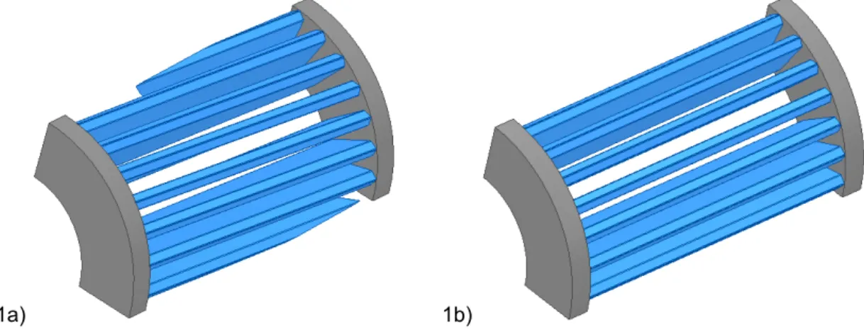
This solution was widely studied in several scientific papers and used as a standard solution in some commercial induction motors. In this rotor, all the bars of the squirrel-cage present the same skew regarding the shaft of the motor. The rotor bar skew was chosen aiming to efficiently reduce the electromagnetic noise produced by the motor. It is illustrated in figure 1a.
Straight Bars (stb_nr)
This rotor was used as the control solution. The bars of this rotor are parallel to the shaft of the motor, presenting no skew angle, and connecting the two short-circuit rings located on both ends of the rotor. It is illustrated in figure 1b.
1a) 1b)
Figure 1 - Representation of a segment of a rotor. 1a) Skewed bars; 1b) Straight bars. Straight Bars and Middle Ring (stb_r)
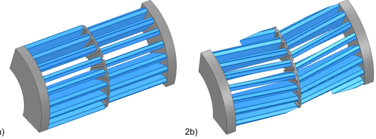
The inclusion of these rotors aims to understand the influence of the use of a middle ring in a squirrel-cage rotor. All the bars are straight and parallel to the motor shaft, but there is a middle ring that short-circuits all the bars, located at the half-length of the rotor. In this middle ring, the bars also present a stagger angle. This stagger angle is defined in the circumferential direction, and measure the angular distance between two consecutive bars, each one from a different side of the middle ring. It is illustrated in figure 2a.
Skewed Bars and Middle Ring (skb_r)
This rotor uses both characteristics studied in this article. It has skewed bars and also a middle ring, presenting same stagger angle. With this rotor, the objective is to test the hypothesis that these two designs have a redundant effect on the performance on the steady state on induction motor. It is illustrated in figure 2b.
2a) 2b)
Figure 2 - Representation of a segment of a rotor. 2a) Straight bars and middle ring; 2b) Skewed bars and a middle ring.
4. Sizing of the Models in Analysis
Skew Angle
In [1] and [10] it is presented that the skew angle which produces a more efficient effect on the reduction of electromagnetic noise is the one with a value similar to the stator slot pitch. To compare the performances of alternative motor designs, the skew angle was sized to be equal to one stator slot pitch.
Stagger Angle
The value of the stagger angle was definied using the same principles used for the skew angle. According to [10], it is concluded that half of the slot pitch is the optimal value of the stagger angle, so the same value is used in the design of the rotor included in this study.
Middle Ring
The process of sizing the middle ring is more complex than the process of defining the previous angles. The middle ring cannot be oversized, because it will cause an increase in the saturation of the magnetic core of the rotor.
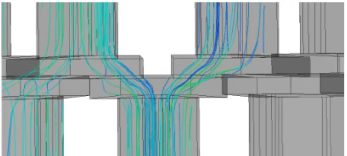
The current, at the end of each bar, will split in two directions, corresponding to the two adjacent bars on the opposite side of the middle ring, as shown in figure 3. The figure of electrical current distribution was obtained from numerical simulations using the Finite Element Method.
Therefore, it is important to guarantee that the cross-section of the middle ring is not smaller than the half cross-section of the bars, avoiding the increase of the rotor Joule losses.
Considering these constraints, it was decided to size the cross-section of the middle ring to avoid an increase in the rotor Joule losses, using a shape that minimizes the total volume of the middle ring.
Figure 3 - Distribution of the electrical current in the middle ring.
5. Characteristics of the Machine
The motor used in this article was chosen taking into account the production cost and rated power of the prototypes. For the purpose of studying the distribution of the losses, the rated power could not be too low, because the difference between the losses measured with the different rotors could be significantly affected by the measuring accuracy of the equipment.
For the purpose of the laboratory tests, the same stator was used, and the rotors were changed. The stator is the same used in an ordinary three-phase induction motor with four poles and 36 slots. The stator winding is single layer with concentric coils.
Although four different rotors were tested, all of them share some characteristics, like 28 slots and aluminum single cage with deep rotor bars. The shape of the bars is also identical for these four rotors. Table 1 presents the rated characteristics of the machine tested.
Table 1 - Rated Characteristics of the Machine.
Quantity Unit Value
Power kW 5.5 Voltage V Y 380 / Δ 220 Frequency Hz 60 Current A Y 11.8 / Δ 20.4 Torque N.m 30.2 Speed rpm 1740
Power Factor (cos 𝜑𝜑) - 0.79
Efficiency (η) % 90.0
6. Laboratory Tests
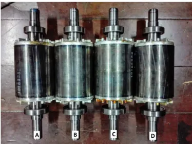
The four prototypes described above were subjected to several laboratory tests, like performance test in steady state, torque-speed curve and noise test at rated load. To reduce the influence of external factors on the laboratory results, the same stator was used for testing all the different rotors. The
laboratory tests procedures were the same for all the different prototypes. They were done three times for each prototype, and had one prototype for each of the models analyzed, as shown in figure 4.
Performance Test
The performance test was based on IEC 60034-1 - Rotating Electrical Machines - Part 1: Rating and Performance [15]. The input power, the rotation speed and several components of the losses were the parameters analyzed. During the performance test of each prototype, information was collected regarding different load factors: 150%, 125%, 100%, 50% and 25%.
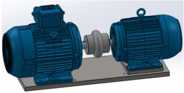
Figure 4 - Prototype for each of the models analyzed. 4a) Rotor with skewed bars; 4b) Rotor with straight bars; 4c) Rotor with straight bars and middle ring; 4d) Rotor with skewed bars and middle ring.
Torque-speed curve
This test was based on the IEEE 112 - Test Procedure for Polyphase Induction Motors and Generators [16]. In this test, the objective was to trace the curve relating the torque with the rotation speed of the motor. However, due to the limitations of laboratory equipment, this test was done using 260 V (Y) at 60 Hz, instead of rated voltage.
Noise Test
The purpose of the noise test was to measure the noise at rated load. This test procedure is similar to the back-to-back test with two induction motors. The machine under test (each selected prototype) works as a motor directly connected to the laboratory grid. The other machine is also an induction motor, but with a higher rated output power. This second machine is fed by a variable-speed drive (VSD) with torque limitation and a smaller rotation than the prototype motor. The control of torque of the second motor allows the control of the load factor of the first motor. The objective of this test is only to measure the noise of the first motor (and not the noise produced by both machines). To accomplish this goal, a special chamber was used around the second motor for acoustic isolation, and the motor inside the chamber worked without a cooling fan. Thus, only the noise produced by the first motor was measured.
In addition, the test was done in an acoustic chamber to ensure that outside noise do not interfere on the results. Figure 5 illustrates this noise test setup, except for the acoustic chamber. All conditions indicated in [17] for noise tests on a running motor in the nominal load factor were respected. The results are more useful if used for comparative analysis, instead of the absolute values alone.
Figure 5 - Representation of the setup used for the Noise Test (without the acoustic chamber).
7. Results
Performance Test
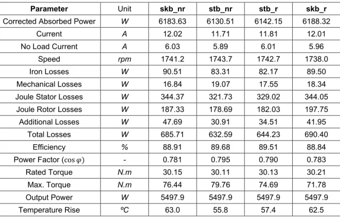
Table 2 shows the overall performance test results referring to the four prototypes described in section 3. The values were measured for each prototype running at rated load.
The results presented on table 2 are the average values of the three performance tests done for each prototype. To directly compare the results between different prototypes it was necessary to ensure that the output power did not differ by more than 1% from each other. The performance test in steady state were done by continuously controlling the output power of the motor, reducing the error to minimum values.
Analyzing the rotation speed in the rated load allows to infer that the rotors with skewed bars tend to have a higher slip, consequently, they generate more Joule rotor losses, leading to a lower efficiency.
Due to the higher slip in rotors with skewed bars, the rated torque is higher. Then the electrical current and Joule stator losses also increase and reduce the efficiency of the motor.
The higher slip in rotors with skewed bars generate higher rotor Joule losses, leading to a lower efficiency of the motor. Besides, the skewed bars also tend to raise the iron losses when compared with straight bars. In table 2, the iron losses include both stator and rotor, and since the stator is the same for the four prototypes, the deviations are due to the presence of different rotors.
Regarding the motor power factor, the results show a tendency of not being significantly affected by the presence of a middle ring in the squirrel-cage rotor. However, the difference in power factor between the skewed-bar rotors and straight-bar rotors tends to be significant and higher for the first ones. The analysis of the results in table 2 allows to infer how each rotor influences the electrical characteristics of the motor. The prototype having a rotor with straight bars and no middle ring (stb_nr) presents the highest efficiency, as predicted in [1]–[4]. However, the prototype having a rotor with
straight bars and a middle ring (stb_r) presented better electrical characteristics than the one having a rotor with skewed bars and no middle ring (skb_nr), which indicates that this solution can be interesting for the industry purposes.
Table 2 - Results of the performance test (load factor = 100%).
Parameter Unit skb_nr stb_nr stb_r skb_r
Corrected Absorbed Power W 6183.63 6130.51 6142.15 6188.32
Current A 12.02 11.71 11.81 12.01
No Load Current A 6.03 5.89 6.01 5.96
Speed rpm 1741.2 1743.7 1742.7 1738.0
Iron Losses W 90.51 83.31 82.17 89.50
Mechanical Losses W 16.84 19.07 17.55 18.34 Joule Stator Losses W 344.37 321.73 329.02 344.05
Joule Rotor Losses W 187.33 178.69 182.03 197.75 Additional Losses W 47.69 30.91 34.51 41.95
Total Losses W 685.71 632.59 644.23 690.40
Efficiency % 88.91 89.68 89.51 88.84
Power Factor (cos 𝜑𝜑) - 0.781 0.795 0.790 0.783 Rated Torque N.m 30.15 30.11 30.13 30.21
Max. Torque N.m 76.44 79.76 74.69 71.78
Output Power W 5497.9 5497.9 5497.9 5497.9
Temperature Rise ºC 63.0 55.8 57.4 62.5
Torque-speed curve
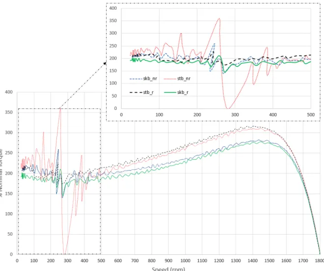
Figure 6 shows the torque-speed curve for each of the tested rotors. It is possible to notice that the motors with different rotors can be split in two different groups: one with straight bars (stb_nr and stb_r) and other with skewed bars (skb_nr and skb_r). The division of the tested prototypes in these two groups shows the influence of the skew angle on the developed torque, although the inclusion of a middle ring also has an important influence, mainly for high slip (region of low rotation speed).
Figure 6 - Torque-speed curve of the four prototypes.
As expected in [1]-[4], both the breakdown torque and the starting torque are lower in motors having rotors with skewed bars when compared with the rotors having straight bars.
For the rotors with straight bars (stb_nr and stb_r) the influence of the addition of the middle ring to the squirrel cage is relevant, mainly, regarding to asynchronous torque. Seemingly, the presence of the middle ring will decrease the asynchronous torque generated by the rotor harmonics, mainly for high slip values (5ª and 7ª harmonic). This is a big advantage that make the motors suitable for a wide range of applications. For example, the motor with a torque-speed curve as the one presented by the prototype
str_nr would be unsuitable for application that require a start with load.
Analyzing only the torque-speed curve results, the prototype having a rotor with straight bars and middle ring (str_r) seem to be a solution with the lowest asynchronous torque values, a higher breakdown and starting torque. The prototype having a rotor with straight bars and no middle ring (str_nr) shows the highest breakdown and starting torques, but it also shows significant asynchronous torque values. The prototype having rotors with skewed bars present very similar torque-speed curves, which may lead to the conclusion that the middle ring is not relevant in rotors that already have skewed bars.
Noise Test
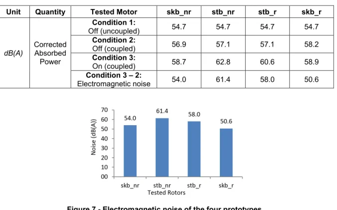
During the noise test of the prototypes, several measurements were made at different conditions. The noise was measured at three different points, all equidistant from the tested motor. Besides that, the noise was measured at three moments during test. First, with only the auxiliary machine inside the acoustic chamber turned on and uncoupled from the tested motor. Second, with the auxiliary machine inside the acoustic chamber turned on and coupled to the tested motor Third, with both machines turned on and the tested motor at rated load. Measuring the noise in these three moments enables to isolate the electromagnetic noise from the mechanical noise. The average results of the measurements at the different points are shown on table 3.
The electromagnetic noise produced by each prototype was calculated by subtracting the noise measured at moment b) from the one measured in c), and it is represented in figure 7. A logarithmical subtract was used because the noise is expressed in dB(A).
Table 3 - Results of the noise test.
Unit Quantity Tested Motor skb_nr stb_nr stb_r skb_r
dB(A) Corrected Absorbed Power Condition 1: Off (uncoupled) 54.7 54.7 54.7 54.7 Condition 2: Off (coupled) 56.9 57.1 57.1 58.2 Condition 3: On (coupled) 58.7 62.8 60.6 58.9 Condition 3 – 2: Electromagnetic noise 54.0 61.4 58.0 50.6
Figure 7 - Electromagnetic noise of the four prototypes.
As expected, the prototypes having rotor with straight bars presents higher electromagnetic noise levels. This is expected due to the significant influence of the harmonic components in the torque produced. Both the skewed bars and the middle ring have significantly influence on the electromagnetic noise produced, and both tend to reduce it. The rotors that have skewed bars (skt_nr and skt_r) were the ones that produced less electromagnetic noise. However, the combination of the two characteristics (skewed bars and middle ring) leads to a rotor with the lowest electromagnetic noise level. The lower electromagnetic noise is due to the capacity of these two characteristics to reduce the amplitude and influence of the harmonics in the air-gap magnetic flux.
The rotor with only the middle ring and straight bars (stb_r) presents a significantly lower level of electromagnetic noise when compared with the rotor with straight bars and no middle ring (stb_nr). This shows that the capacity of the middle ring to reduce the presence of harmonics in the air-gap magnetic flux is also relevant.
8. Conclusion
The results obtained from laboratory tests present new similarities between the rotors with skewed bars and rotors with middle ring, also they are in accordance with the relevant bibliographies.
The redundant effect of the skewed bars and of the middle ring is confirmed regarding the torque-speed curve, since the differences between the prototype skb_nr and skb_r are not relevant, particularly, in the low speed region. During the performance test, the two prototypes having rotors with skewed bars present slight differences, but in an overall assessment they look very similar. However, the noise test showed a large difference between these two prototypes, being that the rotor with skewed bars and middle ring presented the lowest noise.
Analyzing the characteristics of each prototype, the rotor with straight bars and no middle ring apparently has the most favorable electrical characteristics, being the motor that reached the higher efficiency. However, the asynchronous torque and the level of electromagnetic noise produced limit the range of application in which this rotor design can be used.
On the opposite, the rotor with skewed bars and middle ring presented the lowest level of electromagnetic noise among the four prototypes tested, but its rated load efficiency was the lowest. The developed torque is quite similar to the rotor with skewed bars and no middle ring, which is the most common industrial solution.
Both the rotor with straight bars and middle ring and the rotor with skewed bars and no middle ring presented good characteristics. The skb_nr presented a lower level of electromagnetic noise and the
stb_r presented a higher torque curve with lower asynchronous torque and higher efficiency.
Based on these results, the use of a rotor with skewed bars and/or with a middle ring can lead to interesting differences on motor performance. The choice of the best option will depend on the application of the electrical motor.
References
[1] S. Nau, “The influence of the skewed rotor slots on the magnetic noise of three-phase induction motors,” Eighth International Conference on Electrical Machines and Drives, 1997.
[2] Z. Ferkova and V. Kindl, “Influence of Skewed Squirrel Cage Rotor with Intermediate Ring on Magnetic Field of Air Gap in Induction Machine,” Elektronika ir Elektrotechnika, vol. 23, no. 1, 2017.
[3] L. Wang, X. Bao, C. Di, and Y. Zhou, “Influence on Vibration and Noise of Squirrel-Cage Induction Machine With Double Skewed Rotor for Different Slot Combinations,” IEEE Transactions on
[4] L. Wang, X. Bao, C. Di, Y. Zhou, and Q. Lu, “Analysis of synchronous parasitic torque in dual skew cage rotor induction motors with equivalent slot number,” IET Electric Power Applications, vol. 11, no. 8, pp. 1357–1365, Jan. 2017.
[5] S. Williamson and C. McClay, “The effect of axial variations in saturation due to skew on induction motor equivalent-circuit parameters,” IEEE Transactions on Industry Applications, vol. 35, no. 6, pp. 1323–1331, 1999.
[6] X. Bao, J. Fang, C. Di, and S. Xu, “A Novel Computational Method of Skewing Leakage Reactance for Doubly Skewed Rotor Induction Motor,” IEEE Transactions on Energy Conversion, pp. 1–1, 2018.
[7] D. Dorrell, T. Miller, and C. Rasmussen, “Inter-bar currents in induction machines,” IEEE
Transactions on Industry Applications, vol. 39, no. 3, pp. 677–684, 2003.
[8] S. Williamson, L. Lim, and M. Robinson, “Finite-element models for cage induction motor analysis,” IEEE Transactions on Industry Applications, vol. 26, no. 6, pp. 1007–1017, 1990. [9] K. Yamada, Y. Takahashi, and K. Fujiwara, “Simplified 3-D Modeling for Skewed Rotor Slots With
End-Ring of Cage Induction Motors,” IEEE Transactions on Magnetics, vol. 52, no. 3, pp. 1–4, 2016.
[10] W. Xu, X. Bao, C. Di, L. Wang, and Y. Chen, “Optimal Angle Combination for Improving Electromagnetic Torque in Induction Motor With Double-Skewed Rotor,” IEEE Transactions on
Magnetics, vol. 53, no. 11, pp. 1–5, 2017.
[11] D. Strbac and R. Gottkehaskamp, "Improvement of the operating behavior of small induction motors by finding an optimal rotor skewing angle and a harmonic distribution of the number," IKMT 2015; 10. ETG/GMM-Symposium Innovative small Drives and Micro-Motor
Systems, 2015, pp. 1-7.
[12] H. D. Gersem, K. Hameyer, and T. Weiland, “Skew interface conditions in 2-D finite-element machine models,” IEEE Transactions on Magnetics, vol. 39, no. 3, pp. 1452–1455, 2003. [13] S. Williamson and C. Mcclay, “The variation of cage motor losses with skew,” IEEE Transactions
on Industry Applications, vol. 36, no. 6, pp. 1563–1570, 2000.
[14] A. M. Odok, “Stray-Load Losses and Stray Torques in Induction Machines,” Transactions of the
American Institute of Electrical Engineers. Part III: Power Apparatus and Systems, vol. 77, no. 3,
pp. 43–53, 1958.
[15] IEC Rotating electrical machines – Part 1: Rating and performance, IEC Standard 60034-1, 2017. [16] IEEE Test Procedure for Polyphase Induction Motors and Generators, IEEE Standard 112, 2017. [17] Acoustics – Determination of sound power levels and sound energy levels of noise sources using sound pressure – Engineering methods for an essentially free field over a reflecting plane, ISO International Standard 3744 , 2010.