Março, 2016
André Bernardo Quintanova
[Nome completo do autor]
[Nome completo do autor]
[Nome completo do autor]
[Nome completo do autor]
[Nome completo do autor]
[Nome completo do autor]
[Nome completo do autor]
Licenciado em Ciências da Engenharia Eletrotécnica e de Computadores [Habilitações Académicas] [Habilitações Académicas] [Habilitações Académicas] [Habilitações Académicas] [Habilitações Académicas] [Habilitações Académicas] [Habilitações Académicas]
Hybrid System of Distributed Automation
[Título da Tese]
Dissertação para obtenção do Grau de Mestre em Engenharia Eletrotécnica e de Computadores
Dissertação para obtenção do Grau de Mestre em [Engenharia Informática]
Orientador: Doutor Luís Filipe Figueira Brito Palma, Professor Auxiliar, Faculdade de Ciências e Tecnologia da Universidade Nova de Lisboa
Júri:
Presidente: Doutor João Francisco Alves Martins
Arguente: Doutor João Almeida das Rosas
Vogal: Doutor Luís Filipe Figueira de Brito Palma
Hybrid System of Distributed Automation
Copyright © André Bernardo Quintanova, Faculty of Sciences and Technology, University.
The Faculty of Sciences and Technology and the New University of Lisbon have the perpetual right and without any geographical boarders, to file and publish this dissertation, trough printed copies in paper, digital form or any other known form that might be invented. It can also be publicized in scientific repositories and to admit your copy and distribution with education and investigation purposes, not commercial, as long as the credit is given to the author and editor.
Acknowledgments
Firstly I want to thank my parents for always motivating and supporting me along this academic stage of my life.
I would like to thank Professor Luis Brito Palma, advisor of my dissertation, for the opportunity, support and for enduring my ramblings.
To my friends Vasco Brito and Afonso Maria for traveling with me through this journey. And to my friend Ana Areias for reviewing my dissertation.
Additionally I would like to thank Tucker Emerson and the Kepware Company for helping me in technical issues and for giving me a yearly license to all of their products.
Abstract
One of the most important tendencies in the development of the industrial automation is the application of intelligent control systems within factories, which focuses heavily on networked architectures. Following this line of thinking, the goal of this dissertation resumes itself in the implementation of a distributed system that controls two physical processes, where the system components not only trade information between each other, but also have that same information be accessible remotely and within HMI equipment.
The controllers were conceptualized to offer different functional modes with high customization available.
This system also takes resource of an OPC server, so it allows, not only the communication between different manufacturer PLC controllers but also the connection with remotes clients
The implemented remote clients hold the intent of demonstrating the versatility of this architecture and are, namely, an operational historian that registers information and a data viewer, which allows the use of more advanced methods of monitoring.
Keywords: Distributed System, Programmable Logic Controllers
Resumo
Uma das mais importantes tendências no desenvolvimento da automação industrial é a aplicação de sistemas de controlo inteligentes, no ambiente de manufatura, que focam arquiteturas fortemente baseadas em redes de comunicação. Seguindo esta linha de pensamento, o objetivo desta dissertação resume-se na implementação de um sistema de controlo distribuído de dois processos físicos, onde os componentes não só trocam informação entre si, como essa mesma informação é acessível remotamente e por equipamento HMI.
Os controladores foram implementados de forma a oferecerem diversos modos de funcionamento com alta vertente de customização.
Este sistema também recorre a um servidor OPC de forma a não só possibilitar a comunicação ente controladores de fabricantes diferentes como também a conexão a clientes remotos.
Os Clientes remotos implementados possuem o intuito de demonstrar a versatilidade desta arquitetura e são, nomeadamente, um historiador operacional onde toda a informação é registada e um visualizador de informação, que possibilita a implementação de métodos de monitorização mais avançados.
Palavras-chave: Sistema Distribuído, Controladores Lógicos
Acronyms
AC Alternating Current
AR Auto Regressive
ASCII American Standard Code for Information ……..Interchange
CAN Control Area Network
CPU Central Processing Unit
DC Direct Current
DCS Distributed Control System
DP Distributed Periphery
EPROM Erasable Programmable Read Only Memory
FBD Function Block Diagram
HMI Human Machine Interface
HZ Hertz
IL Instruction List
I/O Input/Output
IP Internet Protocol
JMP Jump
LAN Local Area Network
LD Ladder Diagram
LRC Longitudinal Redundancy Check
OPC Open Protocol Communication
OSI Open Systems Interconnection
PA Process Automation
PAC Programmable Automation Controllers
PCA Principal Component Analysis
PLC Programmable Logic Controller
RAM Random Access Memory
RFID Radio-Frequency Identification
ROM Read Only Memory
RPM Rotation per minute
RTR Remote Transmission Request
RTU Remote Terminal Unit
SCADA Supervisory Control and Data Acquisition
SFC Sequential Function Chart
SRR Substitute Remote Request
ST Structured Text
SVD Singular Value Decomposition
TCP Transmission Control Protocol
USB Universal Serial Bus
Nomenclature
𝒖 Control Signal
𝒚 Sensor Value
𝒓 Set-point value
𝒆 Set point error
ê Set point error
𝑷(𝒕) Proportional Component
𝑰(𝒕) Integral Component
𝑲𝒑 Proportional Gain
𝒀𝒏𝒏 Predicted Sensor Value
𝝈𝟐 Control Action Variance
𝑰𝑯𝒂𝒓𝒓𝒊𝒔 Normalized Harris Index
𝑺 Covariance Matrix
𝝀𝒊 Eigen values
𝑷𝒊 Eigen Vectors
𝑻 Score Vector
Table of Contents
Acknowledgments ... v Abstract ... vii Resumo ... ix Acronyms ... xi Nomenclature ... xv 1. Introduction ... 1 1.1 Motivation ... 1 1.2 Goals ... 2 1.3 Contributions ... 2 1.4 Thesis Organization ... 32. State of the Art and Technology ... 5
2.1 Industrial Automation... 5
2.1.1 Types of Automation ... 6
2.1.2 The Evolution of Automation ... 7
2.2 Programmable Logic Controllers ... 13
2.2.1 Structure and functioning ... 14
2.2.2 Programming Languages ... 17
2.2.3 Current State and Developments ... 22
2.3 Distributed Control Systems ... 23
2.3.1 Production methods ... 23
2.3.2 Structure and Types of DCS ... 25
2.3.3 Comparison with other typical Control Systems ... 27
2.3.4 Current State and Developments ... 28
2.4 Industrial Networking ... 29
2.4.1 Structure ... 29
2.4.2 Comparison with Commercial Networks ... 32
2.4.3 Protocol Overview ... 33
2.4.4 Current State and Developments ... 43
2.5 Brief Chapter Conclusion ... 43
3. Architecture and Implementation ... 45
3.1 Architecture and general functionality ... 45
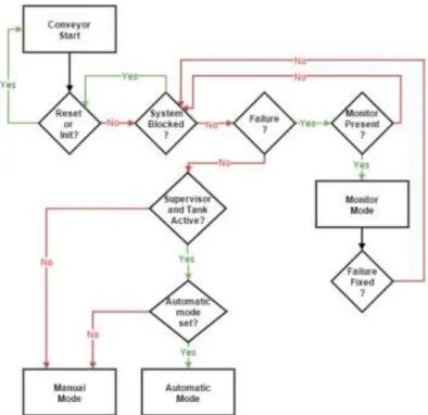
3.2 Conveyor Control System ... 48
3.2.1 Process Structure and specifications ... 48
3.2.2 Operational Description ... 49
3.2.3 Hardware Composition and Implementation ... 52
3.2.4 Software Methodologies ... 54
3.3 Tank Control System ... 57
3.3.1 Process Structure and specifications ... 57
3.3.2 Operational Description ... 58
3.3.3 Hardware Composition and Implementation ... 63
3.4 Supervision and Monitoring ... 67
3.4.1 Operational Description ... 68
3.4.2 Hardware Composition and Implementation ... 71
3.4.3 Software Methodologies ... 71
3.5 Open Protocol Server and Communication ... 74
3.5.1 Operational Description ... 74
3.5.2 Software Methodologies ... 76
3.6 Remote Clients ... 77
3.6.1 Operational Historian ... 77
3.6.2 Advanced Data Viewer ... 79
4. Experimental Results ... 85
4.1 Conveyor Testing ... 85
4.2 Tank’s Sensor Testing ... 86
4.3 Tank’s Controller Testing ... 87
4.3.1 PI Controller ... 88
4.3.2 Switched PI Controller ... 89
4.3.3 PI Controller with Model Rectification ... 90
4.3.4 Comparison between Controllers ... 91
4.3.5 Side notes relating to Remote Client Methodologies ... 91
4.4 Communications ... 92
5. Conclusions ... 93
5.1 General Conclusion ... 93
5.2 Awards and Honors ... 94
5.3 Future works ... 94
Bibliography ... 95
Appendix ... 99
B. I/O Tables ... 101 C. Operational Historian Log ... 105 D. Communication between Components ... 106
Figure List
Figure 2.1 - Tesla Manufacturing line [1]. ... 6 Figure 2.2 - Automation progression timeline. ... 8 Figure 2.3 - Ancient water clock illustration [8]. ... 8 Figure 2.4 - An example of a steam governor [9]. ... 9 Figure 2.5 - The first Programmable logic Controller Modicon 084 [10]. .. 10 Figure 2.6 - RFID usage on smart manufacturing of bottles [12]. ... 12 Figure 2.7 - Additive manufacturing principle [16]. ... 13 Figure 2.8 - A PLC industrial cabinet [20]. ... 13 Figure 2.9 - A PLC high level cycle of operation. ... 15 Figure 2.10 - PLC hardware structure. ... 15 Figure 2.11 - PLC Memory structure. ... 16 Figure 2.12 - Example of a simple button activated timer in Ladder. ... 18 Figure 2.13 - Example of a simple alarm in FBD. ... 19 Figure 2.14 - Example of a conditional allocation in IL. ... 20 Figure 2.15 - Example of a robot movement routine code via SFC. ... 20
Figure 2.16 - Example of an average value calculation code via ST. ... 21 Figure 2.17 - Typical DCS structure. ... 26 Figure 2.18 - A typical industrial network structure. ... 30 Figure 2.19 - Network Topologies. ... 30 Figure 2.20 - Main protocol models. ... 35 Figure 2.21 - Terminal connectivity classifications. ... 35 Figure 2.22 - Modbus protocol transaction. ... 36 Figure 2.23 - Modbus message framing. ... 37 Figure 2.24 - Profibus protocol transaction. ... 39 Figure 2.25 - Profibus message frame... 40 Figure 2.26 - OPC application scheme. ... 42 Figure 2.27 - OPC client-server conceptual structure. ... 43 Figure 3.1 - Hybrid System of Distributed Automation. ... 46 Figure 3.2 - Global system scheme. ... 47 Figure 3.3 - Conveyor System. ... 48 Figure 3.4 - Conveyor illustration. ... 48 Figure 3.5 - Conveyor main sequential logic. ... 49 Figure 3.6 - Manual mode main features. ... 50 Figure 3.7 - Automatic mode logic scheme. ... 51 Figure 3.8 – Main features of monitoring mode. ... 51 Figure 3.9 - Hardware configuration scheme... 53 Figure 3.10 - Sensors used within the Conveyor (contact relay and infra-red optical sensor). ... 54
Figure 3.11 - Step 7®/ TIA Portal® Software environment. ... 55 Figure 3.12 - Partial code of a transportation task. ... 56 Figure 3.13 - Tank system. ... 57 Figure 3.14 - Tank illustration. ... 58 Figure 3.15 - Tank main logic scheme. ... 59
Figure 3.16 - Manual mode main features. ... 59 Figure 3.17 - Automatic mode logic scheme. ... 60 Figure 3.18 - PI controller block scheme. ... 61 Figure 3.19 - Switched PI controller block scheme. ... 61 Figure 3.20 - Predictive PI controller block scheme. ... 62 Figure 3.21 - Monitoring mode main features. ... 63 Figure 3.22 - Tank hardware configuration scheme. ... 63 Figure 3.23 - Unity Pro® Software environment. ... 64 Figure 3.24 - PI controller code sample. ... 65 Figure 3.25 - Chosen neural network structure. ... 66 Figure 3.26 - Code regarding the model prediction. ... 67 Figure 3.27 - Main manual mode Screen. ... 68 Figure 3.28 - Conveyor anomaly and consequent manual mode screen. .. 69 Figure 3.29 - Custom part specification selection screen. ... 69 Figure 3.30 - Automatic mode screen. ... 70 Figure 3.31 - Failure, monitoring mode screens. ... 70 Figure 3.32 - Emergency block screen. ... 71 Figure 3.33 - Help screens. ... 71 Figure 3.34 - Simatic WinCC/TIA Portal Software environment. ... 72 Figure 3.35 - Failure Trigger screen code. ... 73 Figure 3.36 - Code exert for the Conveyor animation task. ... 74 Figure 3.37 - Communication structure scheme. ... 75 Figure 3.38 - Memory linking between Controllers. ... 75 Figure 3.39 - Illustration of remote information access. ... 76 Figure 3.40 - Instruction logic of the historian client. ... 78 Figure 3.41 - OPC communication code example. ... 79 Figure 3.42 - Operational logic scheme of the data viewer client. ... 80
Figure 3.43 - PCA graphical representation [38]. ... 81 Figure 3.44 - PCA results for controller at nominal work state. ... 82 Figure 3.45 - Viewer monitor interface. ... 84 Figure 4.1 - Conveyor timing diagram. ... 86 Figure 4.2 - Sensor Testing. ... 87 Figure 4.3 - PI Controller behavior. ... 88 Figure 4.4 – Commuted PI Controller behavior. ... 89 Figure 4.5 - PI Controller with model rectification behavior. ... 90 Figure 4.6 – Harris index results. ... 91
List of Tables
Table 1 - Comparison between Types of Automation. ... 7 Table 2 - Comparison between DCS and SCADA. ... 28 Table 3 - Main differences between Industrial and Commercial networks. ... 32 Table 4 - Modbus main function codes. ... 37 Table 5- Supervisor used Inputs ... 101 Table 6- Supervisor used outputs ... 101 Table 7-Conveyor controller used inputs ... 101 Table 8- Conveyor controller used inputs ... 103 Table 9- Tank controller used inputs ... 103 Table 10- Tank controller used outputs ... 104
1. Introduction
In this chapter, the reasoning that led to the execution of this dissertation is done.
In sub-chapter 1.1 it is mentioned the context to what motivated the implementation of this system.
The goals and contributions of this project are descripted in sub-chapter 1.2 and 1.3, respectively.
Lastly, it is given a notion of how the dissertation is organized, in sub-chapter 1.4.
1.1 Motivation
The tendency of the current industrial automation scene relies heavily in the concept of Industry 4.0, which illustrates the implementation and further development of smart manufacturing environments based in strong network communications.
This initiative aims to satisfy customer demands for new, high-quality customized products and, at the same time, reduce production time cycles and resource utilization. Such goal is done by not only heavily networking a manufactory process but also by applying more flexible, open and smart distributed system architectures.
In many manufacturing companies, the used control systems are based in outdated concepts and methods of production with strong sequential logic and controllers with very specific tasks. Additionally, this systems have very rigid structures with small synchronism and interaction foundations. Therefore, this project intends to propose a reliable and cheap distributed system that holds
many of the benefits the concept of Industry 4.0 has to offer (interoperability, interaction, flexibility, autonomy).
1.2 Goals
Initially, the goals of this dissertation resumed themselves to the detailed study of the most important topics concerning distributed systems for the area of industrial automation and control. From programmable controllers and fault detection methodologies, to communication protocols and human-machine interaction. With this notion, the main goal of this dissertation is to present a possible distributed system with high interoperability, supervision and accessibility features.
The system is conceptualized to hold an architecture composed by a varied array of technologies and operational methodologies, where all the main components communicate with each other and the most important information is compatible and accessible remotely. Different manufacturer programmable controllers are used with the goal of making the system more versatile and compatible. It also intends to conjugate different types of SISO controllers and monitoring techniques, permitting several possible work states and different manners of observing control information.
Concerning the contextualization for the application to which the system was developed, it was in regards to the post treatment of stainless steel parts. This method is named pickling, and it is usually applied to a post welding phase. In short, pickling is essentially a timed treatment where the welded parts are submersed in chemical solutions, with the sole goal of fortifying the weakened sectors due to heat exposure.
With this context in mind, this system’s main purpose is to control and monitor the transportation of the part from a prior workstation to the pickling station and its respective chemical treatment procedure.
1.3 Contributions
The main contribution of this project is to present a new concept for industrial systems in an effort to approach the industry 4.0 tendency without it translating in expensive production line restructuration.
In terms of scientific value, this system was centralized in an Open Protocol Communication server, which allows for all of the system’s information to be neutral and available to any of the system’s components (current or future additions). The differentiation comparatively to other systems, is that typical
distributed systems never use servers and networks as the foundation of the system, usually, they are used just for information collection and for high level monitoring.
It also presents a fully functional industrial prototype within the control laboratory, which allows for a didactic way of illustrating the importance of automation and distributed control, presenting several technologies applied within the industry.
1.4 Thesis Organization
This dissertation is constituted by five chapters, including the introduction and is organized in the following manner:
Chapter 2 - State of Art and Technology
This chapter studies the important topics used within the project in an automation aspect. The first section is dedicated to automation in general and its evolution; the second section approaches the important programmable logic controllers. The third section is dedicated to distributed control systems structures and production methodologies. The fourth section focuses on the industrial networking, going over its concepts and the most used communication protocols. The last section concludes and encompasses all of the former described technologies and makes the connection with the project in the following chapter.
The first four sub-sections also describe current developments that give the reader a notion of what is being researched and developed.
Chapter 3 – Architecture and Implementation
The third chapter is dedicated to describing every aspect of the system, from architectures and control methodologies to hardware structure and software implementation.
It is divided in global architecture and in the detailed overview of both physical process control systems, supervision, communication and remote clients.
Chapter 4 – Experimental Results
On the fourth chapter, the main experimental results and notes concerning the main risk factors within the overall system will be presented.
Chapter 5 – Conclusions
On the final chapter, the conclusion of the dissertation is elaborated and the presentation of possible future works following the automation distributed systems area.
2. State of the Art and Technology
In this chapter, it will be approached and explained with some detail the automation thematic within the project. From the theory behind the subjects to popular alternatives, current projects and scientific research being developed.
The sub-chapter 2.1 will briefly go over what automation is and what categories it can be divided onto, its historical development as well as the industrial revolution and the current projects being worked.
The sub-chapter 2.2 is going to describe the main technology behind the industrial Automation, called Programmable Logic Controller (PLC), from the hardware constitution, used programing tools to current developments.
In the section 2.3, the subject is distributed control systems, where the following topics will be discussed: the concept, comparisons against non-distributed systems, applications, manufacturing methods and current developments.
In sub-chapter 2.4 we will focus on industrial networks, which were crucial for the further development of the industrial control systems. We will see how industrial networks are structured and how the specific protocols developed work, as also what differentiates the industrial networks from the commercial networks, as also current researches about the subject.
The sub-chapter 2.5 concludes and encompasses all of the former described technologies and makes the connection with the project in the following chapter.
2.1 Industrial Automation
The concept of automation is, essentially, the creation and implementation of technology that allows monitoring and control of a device, so it possesses the capability to perform a task on its own. Ultimately, having the objective of improving production efficiency and minimizing task associated human intervention.
Such devices might be classified as machinery, factory processes, heat treating ovens, steering and stabilization mechanisms and much more.
Automation is virtually applied in all of the industrial sectors, from manufacturing (Figure 2.1), transportation, to the better use/reach of utilities, building automation and military purposes.
Figure 2.1 - Tesla Manufacturing line [1].
Its concept has been realistically implemented through means that include mechanical, hydraulic, pneumatic, electronic and microprocessor technologies. In the modern times, typical systems include a combination of all of the mentioned above.
It is worth noting that the idea is proved to be applied since the beginning of humanity, but the term itself was adopted after the creation of the automation department from General Motors, in 1947. It was at this time that the vision of fully automated factories was starting to be very prominent in manufacturing companies, especially after continuous research and development, which proceeded the invention of the first feedback controllers in the mid-1700s [2].
2.1.1 Types of Automation
There are many different types and ways of implementing the automation concept. However, they generally fall in the following three categories (comparison made in Table 1):
• Fixed/Hard automation: this category is illustrated by the use of specific
automate components to perform very detailed and simple tasks, usually on lines of production that are mainly structured by sequential operations. Its use is often justified when there is the need of high demand of one kind of product to be manufactured [3][5].
The worst factor associated to fixed automation systems is the incapability of adapting, specially, when it is desired to modify the initial product to which the system was designed. For instance, this type of automation can be found in the automobile industry, steel rolling and paper production.
• Programmable automation: the production equipment in these kinds of
systems is designed to be able to change work states for different product specifications. The operation sequence is coded and programmable, allowing the creation of new configurations and operation states through reprograming [3] [5]. It is associated with this structure, a significantly lower production rate, therefore generally being adopted by factories that have higher priority in product variety comparatively to product demand. For instance, this type of automation can be found in the systems that use numerical controlled machine tools, industrial robots and programmable controllers.
• Flexible automation: this structure is an upgraded concept of
programmable automation with the goal of having the same benefits but with higher production rates. The main difference lies essentially on the fact that there is no time lost between work state changes, therefore, allowing a much faster and variable production sequence [3], [5].
Table 1 - Comparison between Types of Automation.
Fixed Programmable Flexible
Production Rate High Low Medium
Cost Low Medium High
Adaptability Low High Medium
2.1.2 The Evolution of Automation
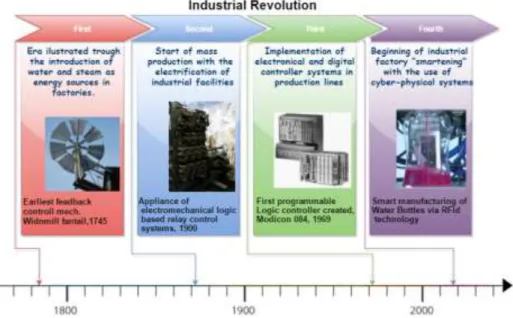
On what concerns automation, it is important to have an insight of how it, developed through the ages into the modern control systems we have today. As observed in the Figure 2.2, the automation evolution was heavily influenced by the Industrial Revolution.
Although the general perception with autonomous controllers is that they are related with factory production structures since the mid 1800’s, there were already existing inventions in the Ancient Greek and Arabic communities that represented the raw concept of automation and most of them were based in the use of float-valve regulators [5][6]. The basic functioning of these regulators are, when open, it would cause the retained liquid to drop with a periodic frequency directly associated with the percentage of the regulator’s opening.
Figure 2.2 - Automation progression timeline.
This almost periodic re-allocation of liquid, made possible the invention of what is believed to be one of the first feedback control devices documented in the history of humanity. That device was the water clock of Ktesibios (Figure 2.3), created in Alexandria, Egypt around 250B.C. [5]. This clock allowed the notion of time to be a quantifiable variable and it was arguably one of the most exact time measuring inventions, until the invention of pendulum clocks in the 17th century [5][6].
Figure 2.3 - Ancient water clock illustration [8].
Patented around 1745 by Edmund Lee, one of the earliest feedback control mechanisms created, was used to manipulate the sails of the windmills, with the purpose of controlling the gap between grinding stones [5][6]. This concept contributed greatly for major advances in control systems around the beginning of the first Industrial Revolution, in the 18th century. In the same time period, as steam and water resources were starting to be used as means of energy, it eventually helped the creation of the first steam engine governor (Figure 2.4), created in 1788 by James Watt.
The steam governor offered a proportional controller that regulated the amount of fuel admitted onto the engine, therefore maintaining a near constant-speed, without providing exact speed control. This mechanism was only considerably acknowledged by scientists when James Maxwell published a paper entitled ‘On Governors’ (1867) that truly established the start of the theoretical foundation for control theory [7].
Figure 2.4 - An example of a steam governor [9].
Besides the research and development around the steam governor and the theory behind it, the 1800’s and early 1900’s eras, are mainly illustrated by the creation of simple process task controllers for temperatures, pressures, liquid levels and speed of rotating machines [6].
With the introduction of electrical energy to the factories by the second Industrial Revolution, a new means of automation was heavily adopted, by using logic, based on electromechanical Relays (created in 1835 by Joseph Henry), due to the high demand of controllers in factories and power plants (1900 through 1920) [5].
This logic was used to facilitate the implementation and representation of manufacturing programs based on relays (typically on-off controllers). With this concept, there was also the adoption of central control rooms, where operators observed charts with periodic acquired data and manually actuated on the factory process (trough switches and/or valves).
Even though the evolution in control theory was quite noticeable, mostly via the concept above as well as innovations in the transportation area (use of gyroscopes for ship stabilization and primitive auto pilot systems), there were still a lot of conceptual challenges [5]. Namely, a lot of confusion in the reason why the controllers presented different behaviors, especially when changed the dynamic and environment the processes the controller was designed for.
In 1932, the concept of negative feedback was understood and implemented, clearing a lot of the former challenges at hand. This concept added the ability of precisely impacting the actuators of a process, in order to get the desired results [5] [6].
Conjoined with the advancement of wired/wireless communication systems, this era (1935-1950) denominated “The Classical Period”, was considered the main basis for the modern controllers [6].
In the mid-1950s, the third phase of the Industrial Revolution started to be noticed through the creation of data processing machines [5]. These devices made possible the beginning of the implementation of digital controllers, which minimized even more the intervention of a human in a factory process. Until then, the control systems were all predominantly analog based and/or used relay concept structures.
During this period, is it also worth mentioning that there were a lot of advancements in control theory, mainly via the acknowledgment that control systems are non-linear and the existence of significant errors in the sensors caused by noise. There were also new concepts created, such as the use of physical behavior equations and “black box models” [6].
All of these concepts being developed, along the significant fall of prices in digital processor devices, led to the considered official beginning of the third Industrial Revolution, with the creation of the Programmable Logic Controller (Figure 2.5). This device helped minimize significantly the costs associated, mainly to the constant re-calibrating of already existing controllers implemented, by allowing a means of reprogrammable higher logic take place in the factories, and also by offering tools with programing languages that were easily understood and used by their own factory technicians [5].
This era was mostly translated by evolving the industry through the implementation of electronics and digital controllers.
The current era, denominated by fourth Industrial Revolution or Industry 4.0, is mainly illustrated by bringing communication systems (e.g. internet network technologies) into the factories, with the goal “smartening” the industrial processes. Allowing further efficiency and profit, through the creation of long distance distributed control systems, where each component of the production line, autonomously communicates with each other and adjusts itself to a required functioning state.
This era primarily focuses on the development of concepts that use the following principles [11]:
• Interoperability: every main machinery has to be capable to
communicate autonomously through the internet;
• Virtualization: data bases full of acquired information associated
with virtual models of the real production line implemented;
• Real-time data acquisition;
• Decentralized systems: the ability of each component making
decisions on its own;
• Information accessible without location restrictions;
• Flexibility: easy adaption of each component to different desired
work tasks;
Due to most stakeholder’s natural inertia into investing on further developing already existing factories, this era is still on its early ages. However, the believed tendency is to see complex networks being more prominent in lines of production in the coming years.
2.1.3 Current State and Developments
The ultimate goal of the global current research is to bring to reality viable and effective implementations of the concept of Industry 4.0; in other words, to create smart factories that are extremely networked, distributed and flexible.
This sub-chapter will approach a few researches that approach the main theme of automation.
On what concerns advancements in interoperable and distributed systems, there is a concept being developed where every material resource and
component of a product has a special RFID tag, as shown in Figure 2.6 [12][13]. When going through the assembly line, those materials are able to communicate with each other, allowing the identification of which materials should go through the same route, in order for a specific product to be created. Furthermore, each assembler robot is integrated with a scanner to read the information from the group of materials and consequently know exactly which manufacturing task to perform. This concept relies greatly on the use of radio frequency identification chips, and it is considered a main future tendency on what concerns factory layout and product planning optimization.
Figure 2.6 - RFID usage on smart manufacturing of bottles [12].
There are also being developed major industrial projecting and implementation tools trough virtual 3D prototyping [14]. These tools rely on the idea that while creating the 3D model of the desired product, at the same time, the program would be able to project the entire production line and machinery associated, offering specific market analysis on the materials needed. This would significantly lower initial placement costs by companies.
Another aspect being researched focuses on human resource advancements. The idea is based on consolidating, in real time, the factory manufacturing operations with the available workers, considering their many individual chrono-biological attributes [15].
The workers would be connected to the network at all time, allowing each workstation to acknowledge which employee is to work next, and adapting itself to any possible limitations or disabilities. It would also create a mean of data acquisition, which would be conveyed into more efficient human resource deployment. The main goal of this concept is to add further flexibility onto a factory.
In a last remark, there is a new tendency that came to fruition with the evolving penetration of 3D printing systems into the market [16]. This notion is denominated additive manufacturing and it is based on the use of a new concept
of “3D printing” implemented into conventional manufacturing lines (Figure 2.7). The concept uses as resource materials that can be presented in the form of fine powder, and what it does is constructing components (simple or complex) layer by layer, contrary to the current concept used of 3D printing that is based on milling techniques.
Figure 2.7 - Additive manufacturing principle [16].
2.2 Programmable Logic Controllers
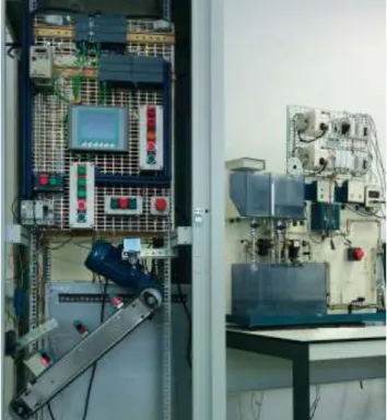
A PLC is a digital device that processes, in real time, the acquired information from an industrial equipment to which is coupled with (typically the ones that resort to electromechanical technology) and consequently manipulates the process into the desired work state (Figure 2.8).
This is done by offering several kinds of digital and analog input/output ports that are compatible with different types of industrial machinery, therefore allowing the reading of sensors and a following calculated actuation on the components of the main process equipment.
As mentioned on the previous chapter, the PLCs were an invention of great significance during the second Industrial Revolution, having the main focus of digitalization of the production environment.
It allowed a new level of flexibility and ease of control by programming and executing logical instructions. The first PLC to be produced was Modicon 084, in 1964.
It is worth noting that this device is still very prominent on the modern industrial scene, largely due to their durability, reliability, cost and ease of technical implementation compared to the more advanced control systems.
2.2.1 Structure and functioning
A PLC normal cycle of work is based on the main following actions (Figure 2.9) [17]:
1. Input Scan: processor time slot reserved to access and verify every single input port acknowledged as in use and note their state changes on the input memory table;
2. Program Scan: with the information gathered in the former action, the CPU takes the new changed/unchanged information retrieved from the input ports check and executes the respective previously programmed sequence of logic instructions. While the instructions are being executed, the output memory table is kept updated;
3. Output Scan: uses the results from the programmed logic that affect output ports by accessing the output memory table and activates/de-activates them by applying or cutting off the hardware designed voltage of each port;
4. System operations: last group of operations in a PLC cycle is reserved for more advanced actions such as communications, diagnostics and so forth.
Figure 2.9 - A PLC high level cycle of operation.
Concerning its hardware structure, it is essentially divided in four sectors: input/output modules, central processing unit (CPU), memory and programming terminal (Figure 2.10) [17].
Figure 2.10 - PLC hardware structure.
Going a bit over the components and starting with the central processing unit, all PLCs are generally based on microprocessor structures. Their function is to control and supervise all the operations within the device itself and execute instructions from the programed logic stored in the memory. All the components communicate periodically with the CPU via a main internal bus system. Some more advanced PLCs are built with more than one CPU, in order to achieve efficiently more complex instructions [17].
On what concerns the memory, PLCs contain both random access and read only modules (RAM/ROM). The memories are composed by the following segments (Figure 2.11) [17]:
Executive Memory: this sector of the memory is ROM type, and it is
where the main manufacturer default system operations are stored. It instructs the PLC on how to scan I/O modules, interpret user programed logic, test and diagnose internal modules.
System Memory: RAM type sector reserved for results and
information of system only operations, such as error codes and module work states.
I/O Image Table: reserved area of the memory that is constantly
being updated with the new values read/wrote from the input/output modules Each I/O port has a dedicated memory slot with an individual address. RAM type of memory applied in this case.
Data Memory: it has a similar way of functioning to the previous
sector mentioned, but applied to instruction logic values that must be stored, such as values that are calculated, or counters and timers being used. Sometimes it is divided into a constant value and variable value area (RAM).
User Program Memory: portion of memory where the code
programmed by the user is allocated, during the CPU work cycle, when the program scan phase is achieved. This is the place from where the CPU takes the operations to execute. Usually comes in RAM format, but can be set in EPROM if desired (a more definitive mean of assuring the information stays allocated).
The programming terminal is what offers the PLC the compatibility to communicate with secondary devices with the intent of being programmed, tested and monitored by the user. The technologies generally offered are through USB variations and several network technologies (Modbus, Serial communication, Ethernet, Etc.)
In regard to the Input/output modules, they are the means to interact with industrial mechanisms that are a part of the control system. Usually, PLCs offer a digital module where the inputs typically work at 24V DC, and the outputs have either a discrete 24V DC functioning or a relay/TRIAC supported output where an output of up to 240V AC/1A can be used. The ports are often electrically isolated to protect the device from any undesired power-supply surges.
2.2.2 Programming Languages
In the implementation of a successful control system using PLCs, there must be a code programed by the user with all necessary operations. In order for that to happen, the PLC offers several programming languages, which initially had the goal of using similar logic and representation to the former techniques applied by the engineers and technicians. In one way, this was one of the biggest factors to the success of such devices, making them easier to implement and modify without the need of specialized technicians and, therefore, more cost effective.
The languages currently supported by the IEC 61131-3 standard for programmable logic controllers are the following:
• Ladder Diagram (LD);
• Function Block Diagram (FBD); • Instruction List (IL);
• Sequential Function Chart (SFC); • Structured Text (ST);
On a side note, most of the PLCs are multi task based, allowing the simultaneous use of combinations of different operations with varied languages. It is also worth mentioning that all variables used, need to be specifically allocated on a space of memory conceptually implemented to handle the type of the variable. Next, the summaries of such languages are presented
2.2.2.1 Ladder Diagram
This language was the first one offered by the initial PLCs created and its main goal was to be simple, useful and, most importantly, easily comprehensible by the technicians. It was designed in such a manner that could visually and conceptually illustrate the important relay logic (very dominant before the digitalization of the industrial environment occurred).
As seen in Figure 2.12, the logic in Ladder offers several “branches” and flows from the left to the right. Each branch can be considered a rule that conceptually starts on the verification of one or several inputs and verifies if they satisfy certain conditions. In other words, verifies if the input variables are activated/de-activated and, if so, it proceeds into the operation phase, naturally altering output variables. All the rules typically run simultaneously in a continuous cycle.
Figure 2.12 - Example of a simple button activated timer in Ladder.
The instructions are made to visually resemble electric wiring. Therefore, the inputs are represented by contacts and the outputs by coils, and both are interpreted as Boolean variables.
This language was conceptualized for tasks that mainly resort to Boolean combinatorial logic, consequently being based mostly in Boolean conditions (e.g..: AND, OR,NOT). Regarding the operations it offers, besides setting a variable “ON/OFF”, there is also the possibility of using counter and timer associated actions in form of pre-programed logic blocks [19].
The foundation of this language and style of programming allows for a global and easy way of use and understanding, especially by the less expert technicians. However, its disadvantage is that, when tasks get complicated, the programming complexity and process resources grow exponentially [18]. Moreover, developing simple sequential structures becomes a very complicated task to implement, and when the code becomes significantly large it is hard to interpret and debug, even when well structured.
2.2.2.2 Function Block Diagram
The conceptual principle behind the Function Block Diagram (FBD) languages is data flow - the information continuously flows through the code from inputs to the outputs (left to right), meaning that the operations between the transition are all done through function blocks.
The function blocks can be sequentially concatenated by connecting the outputs of the former block to the inputs of a subsequent block, therefore facilitating the creation of more complex instructions. The blocks not only offer Boolean logic and simple arithmetic functions, but also comparisons, mathematical functions (ABS, COS, TAN) and can also have user programmed instructions, simplified to a higher level (Figure 2.13).
Figure 2.13 - Example of a simple alarm in FBD.
In contrast to the Ladder language, FBD is usually analyzed from the right (output) to the left (input). And it holds advantages compared to the former mentioned language, in the aspect that is easily analyzed and diagnosed by users that are not familiar with electrical schematics [18].
The FBD is a language that deals very well with simple numerical processing tasks, such as limit verification, scaling, and more. The cons regarding this language are that the larger the code, the harder it is to monitor, edit and analyze.
2.2.2.3 Instruction List
The Instruction List (IL) language is one of the first textual programming tools offered by PLCs [19]. It is considered to be a low level coding tool, similar to the assembly language, and its foundation follows the Accumulator concept. In other words, it represents a chain of mathematical or logical operations that occur in a stepwise fashion, basing the current operation with the results from the previous action.
In this programing language there are several code lines and in each line there is one single operation to be executed that may be applied to a single or several variables (Figure 2.14).
Figure 2.14 - Example of a conditional allocation in IL.
It supports loop programming and conditional verification trough commands like jump (JMP), which takes the execution pointer to an address where the desired following instruction is, as well as offering several arithmetic and comparative operators.
The main advantages of this language lie in the fact that it is textual and condensed, being executed and processed a lot faster, when compared to graphical languages. Furthermore, no specific editors are needed adding a layer of portability to this language. It is also a language generally preferred by programmers that prioritize performance over diagnosing and monitoring [18].
2.2.2.4 Sequential function Chart
The Sequential Function Chart (SFC) is a more flexible adaptation of the Grafcet language, allowing an easier implementation and debugging check of automation systems with a well-defined sequential evolution.
This language can be divided in a sequential way of coding with two main components: action steps/states and conditional transitions (Figure 2.15).
The way it works is: an initial state is triggered, assuring the activation of a group of variables, and if the existent condition in the following transition is satisfied, the system will disable the current state and move onto the next state and its individual variable operations. Transitions can activate several parallel states at the same time. There can be more than one initial state when there are different concurrent tasks within the project.
This language allows simpler code execution, due to the fact that there is no need to scan the whole code each cycle, but rather just the current state and the following transition. This fact also allows fast identification of malfunctioning transitions and "dead end” states [19].
There are several disadvantages worth mentioning. First, amongst the graphical languages, SFC is by far the one that consumes more memory resources, making the execution simpler but a lot heavier and slower. It is also the language that lacks the most in portability - every equipment/software associated has its unique configurations, making it impossible to pass a coded SFC from one source to another without using a third party conversion tool or ultimately having to re-code the whole program [18].
2.2.2.5 Structured Text
Structured Text programming language is the last standardized language offered by the majority of the PLCs produced and sold today. It is the tool with the highest level of programming capability of all the mentioned before in this sub-section. It is often compared to a Pascal language further developed into industrial applications [19].
The language is composed of statements separated by semicolons -these statements can be pre-defined or can be user programmed subroutines (Figure 2.16). The coding is composed by various instructions, such as loop iterations, conditional verifications and further advanced mathematical equations. Every variable is defined previously to the main code of instructions it alludes to, and it can be of the type related to the I/O ports of the PLC internally stored memory types or constant values.
Concerning pros and cons, this tool brings for a more productive means of programming in the current day where the complexity of the problems to be solved have grown very significantly. Besides being well-structured, compact and having more advanced instructions, its highly compatible and consumes lower processing resources. The cons usually mentioned of this language are its textual nature, and the fact that it is arguably harder to diagnose and perform maintenance [18].
2.2.3 Current State and Developments
About the advancements of this technology, it is worth noting that PLC devices have existed for over 40 years and their structure gives great emphasis to programming languages that have been surpassed. Furthermore, the great developments in PC performance and the introduction of Programmable Automation Controllers (PAC) in the industrial market have caused the PLC to decrease in market share dominance of the current manufacturing scene.
Although there is not an established consensus on what should a PAC be or what are the exact differences from a PLC, PAC devices are globally seen as highly advanced PLCs - they hold a more open architecture and modular design, that further facilitates interoperability and communication, more robust PCUs that can perform greater complexity routines, highly developed software tools that bring lower complexity and more modern programming languages to the table (C,C++, JAVA) [22].
PACs do seem to be the successor of the PLCs, technologically wise, but it really depends on the complexity of the control system to be implemented. PACs are very expensive when compared to PLCs, and PLC manufacturers, due to the pressure of the PAC devices market penetration, have been implementing notable upgrades to the current PLCs, from additional CPU features, high speed communication capabilities, larger variety of I/O ports to superior performance and efficiency [21].
There is also a notable philosophical shift in the industrial scene today: the customers do not prioritize individual technology performance but instead focus on global system functioning. Consequently, there has been less focus on buying individual components (PLCs, inverters, etc.) and more emphasis on industrial solution services to create the best global system possible for the situation [22].
A brief conclusion to this sub-chapter is that, even though the PLC devices have been surpassed technologically, depending on the industrial solution complexity and funding, they are still used immensely on the current manufacturing control systems.
2.3 Distributed Control Systems
A Distributed Control System (DCS) is a conceptual automation structure that uses individual controllers and monitoring technologies. The system components are placed strategically throughout the whole industrial plant with the goal of processing/executing specific tasks in large and complex processes. Each component of the DCS communicates in a type of hierarchy level organization, via network, for higher command and supervision purposes [23].
This structure can also be seen as a global system composed of varied sub-systems with individual tasks, contrary to the concept of centralized control systems, where all of the tasks and components of a manufacturing line are controlled and processed through only one main controller. Comparing the two of them, DCSs do bring a higher initial investment cost but portray a higher degree of flexibility, simplicity, control reliability and performance, especially in systems that are subjected to production changes or extensions.
The most valued key feature of this concept is redundancy. DCSs are all designed to accommodate multiple elements that control/monitor the same process component, allowing the existence of back up resources in case of anomalies and/or critical failures. Such feature is extremely important in the modern day mass production industrial lines, where there are major security risks and huge profit losses in case of production stoppage [25].
Applications of DCS are seen over all of the industrial areas, especially the ones that require a higher degree of plant complexity and high cost efficiency, such as power generation, transportation fuel refining, pharmaceutical and highly automated food and beverage production.
2.3.1 Production methods
Before continuing the further description of distributed systems, it is important to enunciate the usual methodologies applied to manufacturing systems, in other words, what are the most common strategies for assembling a commercially viable product. This reason is justified due to the fact of DCS being generally associated to manufacturing processes, so it is important to have a notion of the most used production methods.
In the modern days, it is hard to define a specific factory production structure due to the fact that the industrial scene usually uses combinations of different manufacturing methods that best adapt to their personal goal and cost efficiency. With that in mind, there are three main manufacturing concepts: Job, Batch and Flow production [26].
2.3.1.1 Job Production
Job Production, or One-off production, is a production method that illustrates the execution of custom/personalized work. It is a unique and time constrained kind of service that usually serves as a third party contracted production resource.
This method assures that the product/service created matches the customer needs exactly, and it is usually characterized by highly specialized tasks and quality work. Therefore, it is a significantly expensive method, due to the use of highly skilled staff and time demanding activities [27].
Examples of this kind of production go from building new installations, extending a production line, installing new equipment, maintaining/fixing manufacturing processes to producing highly specialized materials for a new upcoming technology.
2.3.1.2 Batch Production
The Batch production concept lies in producing a fixed number of units to satisfy a certain customer’s order. It is usually best applied in low-mid initial capital companies that produce several types of the same product.
The way it works is as such: if there are 3 types of units to be produced, the factory is set with the needed specifications for one type and produces all the units needed; afterwards, it is reset for the next type of unit. Initially, the raw materials are picked and passed through sequential manufacturing stages that are divided by different workstations.
This method is mostly applied in companies that have no need or cannot afford continuous production. If there is a sudden cut in demand, this method allows production stoppage without suffering huge profit losses (this factor is best suited for factories that produce seasonal items) [27].
Examples of businesses that generally use this method are in the areas of bakery, clothing, pharmaceutical and construction materials.
One method worth mentioning that is usually associated with batch production is Just in Time manufacturing, and it is essentially a more cost effective method that minimizes the investment in resource preparation and storage by ordering and manufacturing the products right before the limit date required by the customer.
2.3.1.3 Flow Production
Flow or Mass production is the method that truly applies continuous assembly of goods. Individual products proceed sequentially from one to another manufacturing phase in a single production line; ach phase has specific staff and mechanisms that perform the same task over and over, as quickly as possible, with minimal quality loss.
Factories that apply this method are meant to be producing 24/7 with high product output so that the overall cost of running the production line is dispersed by each produced unit. Consequently, in cases of stoppage, there are always high costs associated, mostly due to resources needing to be reprocessed and disposed, in order to maintain quality levels in the start of the next work cycle [27].
As it is stated by its name, this method is used in large companies that have a very high demand but small cost flexibility per unit, therefore, being applied in areas such as energy, fuel, electronics, transportation, etc.
2.3.2 Structure and Types of DCS
A distributed control system is, by definition, composed by a hierarchical structure. For further explanation, we shall divide the general structure into three levels [24].
As it can be observed in Figure 2.17, the low-level is composed by the different industrial plant processes and their respective controllers. The processes can go from conveyors, robots, to ovens and are always equipped with easily reachable/compatible actuators and sensors. The controllers are usually custom microprocessors and are responsible for assuring that their respective processes successfully execute the planned manufacturing tasks.
The mid-level is where the supervision controllers are. Their task is to automatically oversee all of the plant controllers, set their work state and possibly detect global system failures.
Servers are installed in this level, which gather all the information available at low and mid-level and, consequently, send it to high level technologies. It is also the place where the lowest means of human intervention is possible by using equipment such as HMIs (screens with graphical interface of the process) and physical buttons.
The industrial network technologies and protocols used at this level are usually the ones supported by the installed HMI and controllers, for example,
serial type, fieldbus and industrial Ethernet communications (such topic will be described on the next sub-chapter 2.4).
The high-level is where specialized tasks are executed, having computers connected to an Ethernet LAN network with the goal of scheduling, coordinating and supervising the whole factory. Databases and remote clients are also available in this level, mainly for further accessibility and reliability.
Figure 2.17 - Typical DCS structure.
On what concerns types of DCS, it is a very subjective matter but through research, it can be divided in the following categories:
Discrete : this is where the conventional DCSs lie and they are basically conceptual systems that control processes of closed loop nature;
Sequential: PLC based systems, typically illustrated by command control, where the notion of states and list of instructions is applied onto a process;
Hybrid: applies both control concepts above;
Smart: these are the most advanced distributed control systems that blur the conventional hierarchy structure by having a higher degree of interoperability and communication between all of its components, making each more independent and autonomous.
2.3.3 Comparison with other typical Control Systems
On the automated manufacturing scene it is important to compare and define the main used systems. Therefore, in this sub chapter, an overview and comparison will be made with SCADA and PLC systems.
2.3.3.1 Comparison with PLC systems
Comparing PLC to distributed control systems, they initially had different applications, PLCs were often used in simple batch controls.
PLC systems presented low component value where it was easy to reset the installation and possible downtime wouldn’t present damage risk onto the process. In counterpart, the DCS was usually applied to much more expensive processes and would have to be able to control critical applications, where a possible failure has high profit loss and security risk associated [23].
In the modern days, it is actually hard to distinguish both systems due to the fact that the evolution of their technology and the adoption of new conceptual manufacturing methods has transitioned both technologies into each other [25]. Therefore being very usual to be observed the use of PLC as plant controllers in distributed systems.
2.3.3.2 Comparison with SCADA systems
A SCADA system is conceptualized for data acquisition with the purpose of plant supervision. It is mainly composed by software, being usually present in higher level layers within the hierarchy of an industrial system.
Its main focus is to gather information and present it to technicians in order for them to monitor and set the processes in correct work states, while DCS is a more process control oriented system.
Comparing both of the systems, as also seen in Table 2, besides DCS being process driven and the SCADA being event driven, there are other noticeable differences in typical systems. Distributed control systems are applied in smaller geographic areas, assuring reliable and good quality data and are composed by closed loop process control.
On the other hand, SCADA systems usually have larger geographical reach and the quality, reliability and determinism of the data is not high priority, since it is used only for monitoring purposes and not for autonomous control. It is also more efficient energetically, due to its equipment only being associated to data processing [25].
Another important factor is the human intervention at process levels. Distributed control systems allow operators to intervene in a more direct manner than a SCADA system would, which only allows HMI interaction. Moreover,, DCS are dependent of a constant stream of data from processes, in order to properly function, while SCADA systems are capable of keeping a well-functioning work state in case of outage, basing its decision on stored data.
Table 2 - Comparison between DCS and SCADA.
DCS SCADA
Process driven Event driven
Small geographic areas Large geographic areas Good data quality and reliability Poor data quality and reliability
Powerful closed loop hardware Power efficient hardware for data processing
Just like PLC and DCS systems identity is very blurry, nowadays, the same happens with SCADA and DCS systems. The common case is that SCADA components are already integrated on modern DCS, which present a very strong component of data gathering and processing.
2.3.4 Current State and Developments
One of the main trends in development on Distributed Control Systems is the conversion of its components into more intelligent interoperable units that focus primarily on the use of wireless communication technologies and networks, specifically in the input/output layer [28].
This layer is one of the most important parts of a DCS where countless process measurements and output actuation signals are read and applied in a single process. The current implementation of I/O devices (I/O Bus network) presents slow value transitions compared to the current developments in technology. The fact that it is based on a wired technology alone makes it more expensive in large industrial plants, while at the same demanding great complexity to assure reliable measurement/actuation of rotating equipment. A second immerging trend is the implementation of server virtualization into the systems [28]. In other words, instead of having a centralized physical server from where every client requests information, that same server is further decomposed into several other virtual servers, which perform their individual tasks and allow access only to entities related to those same tasks. Benefits from this tendency come mainly from higher accessibility and less cost associated to physical resources.
Last but not least, there is also the idea of applying cloud computing into future DCS systems [28]. This would mean that, through remote servers, data would not only be gathered and transmitted, but also major physical tasks would be executed, completely taking away the notion of geographical barriers within a Distributed Control System.
As we can see, the major concerns in this subject relate to general security. In fact, relying on transmission of sensitive information through waves or relying on third party remote servers, if not well conceptualized, can be very risky. Valuable information to a company could be leaked or, even worse, manipulated. Thus, these trends are still far from being implemented on a large scale, especially considering that the automation industry is very conservative by nature.
2.4 Industrial Networking
The constant evolving of the industrial systems into more advanced digitally dependent structures, has also driven the need of developing new and better communication concepts that could fully adapt and elevate the overall performance of the systems.
Initially, the control structures only applied communications between the physical processes and the controllers. However, in the current times, networks are starting to be implemented at all levels, not only from a field control stand point, but also in a supervising and data gathering/processing point of view where the equipment focuses mainly in Ethernet standards.
2.4.1 Structure
Usually, the composition of a traditional industrial network has a significant number of layers and tends to be more complex the bigger the control system is (Figure 2.18).
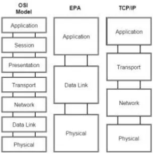
In general, it is illustrated by a hierarchical structure composed by different communication protocols and media equipment where the lowest level of data transmission lies at the connection with the controllers and the physical world; above there is the application level that make the sharing of information between different protocols possible [29].
Following this, there is the supervision and monitoring level, ending on the data collection and external communication layer. This hierarchy has seen a tendency to dissipate, due to constant technological improvements, which facilitated the simultaneous interaction between all the components within a control systems [29].
![Figure 2.6 - RFID usage on smart manufacturing of bottles [12].](https://thumb-eu.123doks.com/thumbv2/123dok_br/15133933.1011142/40.892.209.684.343.610/figure-rfid-usage-smart-manufacturing-bottles.webp)