282 Brazilian Journal of Physics, vol. 33, no. 2, June, 2003
Real-Time Neutron Radiography at the
IEA-R1m Nuclear Research Reactor
M. O. de Menezes, R. Pugliesi, M. A. S. Pereira, and M.L.G. Andrade
Centro do Reator de Pesquisas - CRPQInstituto de Pesquisas Energ´eticas e Nucleares - IPEN/CNEN-SP
Cidade Universit´aria, S˜ao Paulo-SP, Brasil, CEP 05508-970
Received on 30 October, 2002
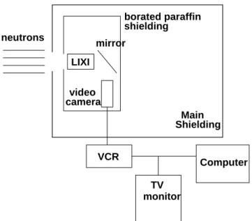
A LIXI(Light Intensifier X-ray Image) device has been employed in a real-time neutron radiography system. The LIXI is coupled to a video camera and the real-time images can be observed in a TV monitor, and pro-cessed in a computer. In order to get the real-time system operational, the neutron radiography facility installed at the IEA-R1m nuclear research reactor of the IPEN-CNEN/SP has been optimized. The most important im-provements were the neutron/gamma ratio, the effective energy of the neutron beam, decrease of the scattered radiation at the irradiation position, and the additional shielding of the video camera. Several one-frame as well as computer processed images are presented. The overall Modulation Transfer Function for the real-time system was obtained from the resolution parameterp= 0.44±0.04mm; the system sensitivity, evaluated for a Perspex step wedge, was determined and the average value is0.70±0.09mm.
I
Introduction
Until the beginning of 1997, the neutron radiography (NR) activities at IPEN-CNEN/SP employed imaging systems composed only by conventional X-ray films and solid state nuclear track detectors with metallic(gadolinium and dys-prosium), scintillator (lithium fluoride) as well as boron con-verter screens [1, 2] . Recently, we have also used a LIXI (Light Intensifier X-ray Image) device to obtain real-time images. In such device, neutron scintillations are amplified by a light intensifier and a video camera captures the result-ing light, given rise to an analog image which can be seen in the TV monitor, and digitized. The resulting one-frame images can be processed in the computer.
The present real-time system has been characterized in terms of its overall Modulation Transfer Function(MTF). In addition it was also verified the system sensitivity to discern thickness.
II
Experimental
The experimental NR facility employed in this work is in-stalled at the beam-hole #08 of the 2MW IEA-R1m nuclear research reactor. In order to get the real-time system op-erational, the original facility designed in 1987, has been improved. Presently, the external shielding has a large inter-nal free space (2 x 2 x 2 m) providing several irradiation positions and a negligible scattered radiation contribution at the irra-diation position. The new Cd-borated paraffin divergent col-limator, 1.5m length leads to a maximum L/D ratio of about 110. The bismuth filter, 25cm thick assures a low gamma radiation contribution to the image formation and reduces the effective energy of the neutron beam. The characteris-tics of the neutron beam depend on the irradiation position inside the shielding, and are shown in Table 1 for the posi-tions where the neutron flux is maximum and minimum. neutron flux 1106n/s.cm2 1.6105n/s.cm2
n/γ 4106n/cm2.mrem 2106n/cm2.mrem
L/D 55 110
effective energy 7meV 7meV
Table 1: Main characteristics of the neutron beam
The LIXI is a device with a 5cm diameter input neu-tron scintillator, which is coupled to a light intensifier(gain
104) . The amplified image is captured by a high
sensitiv-ity – 0.01 lux CCD (Charge Coupled Device) video camera which is attached to a video cassette recorder (VCR), to a
neu-M. O. de Menezeset al. 283
trons by means of an additional borated-paraffin shielding. The TV monitor, the VCR and the computer are installed outside the facility shielding. A schematic diagram of the real-time system is shown in the Fig. 1.
monitor TV Main VCR LIXI mirror shielding borated paraffin neutrons camera video Shielding Computer
Figure 1. Schematic diagram of the real-time system.
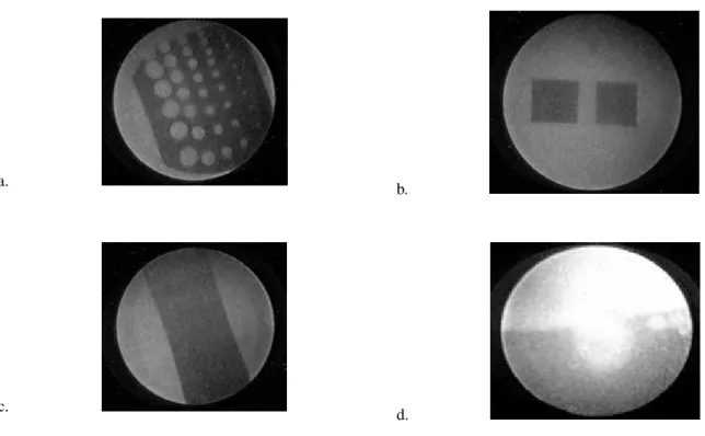
The real-time images were obtained by positioning the LIXI device where the neutron flux is maximum. The im-ages coming from the video camera can be visualized in the TV monitor and stored in a cassette tape or in the com-puter hard disk. The images are digitized by means of a Targa-1000 frame grabber at a rate of 30 frames/sec with 256 gray levels, installed in the computer. Because of hard-ware limitations, the image processing is not performed in real-time. Several experiments have been carried out in or-der to observe static and dynamic objects such as cadmium and gadolinium strips, Perspex step wedge, water movement inside an aluminum cavity. The obtained one-frame images as well as the processed ones are shown in Fig. 2 and Fig. 3, respectively.
The MTF was determined by a conventional method [3], by scanning the image of a neutron opaque mate-rial(gadolinium strip), which has been irradiated in a tight contact with the LIXI scintillator. AnarctanEdge Spread Function (ESF) has been fitted to the resulting pixel inten-sity distribution. By differentiating the ESF, the Line Spread Function (LSF) is obtained and its Fourier transform gives the resulting MTF:
M T F =C·exp(−2πf /p)
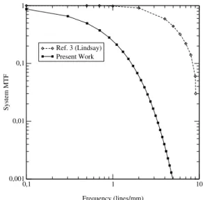
where C is a constant, f is the spatial frequency(lines/mm) and p is the resolution parameter. In Fig. 4 the system MTF corresponding to an average of 75 frames is shown.
The system sensitivity to discern thickness is related to several factors, such as: material thickness (x); total
macro-scopic cross section (ΣT); imaging system performance; ex-posure (E) defined as the product of neutron flux by irradi-ation time (Φt).
Since the neutron transmisstion is governed by the well known exponential law
Φ = Φ0e−ΣT(v)x
and that the light intensity generated in the scintilator (bright
B) is a linear function of the exposure (B ∝ E), we can write:
B=B0e−ΣTx
Considering that the gray levels (g) of the digitized im-age and the gray levels of the analog imim-age are related by a
γfactor given by [6]:
γ= ∆g
g
∆B B
the sensitivity obtained for the digital image can be given by:
∆x= ∆g
γgΣT
where∆g is the minimum discernible change in the gray levels.
The system sensitivity to discern thickness has been evaluated by imaging a Perspex step wedge, with thick-nesses ranging from 2 to 15mm. The step wedge was ir-radiated as close as possible to the LIXI device. From a 75 frames averaged image we performed gray level read-ings (300 pixels) in each step; these readread-ings were averaged arithmetically and the resulting values as a function of the thickness are shown in Fig. 5.
III
Discussion
For similar real-time systems, high level noisy and low con-trast analog images are frequently obtained [4, 5]. However, the present analog images are good in contrast and resolu-tion. This can be a consequence of the low effective energy of the present neutron beam which leads to a high effective cross section for the materials and to a high neutron to pho-ton conversion efficiency of the LIXI scintillator.
In the Fig. 2(a, b, c) and Fig. 3(a, b, c) the one-frame images as well as the processed ones for the static objects are shown. In this case, frame averaging, edge and contrast enhancement has been applied and improvements in image quality have been obtained.
284 Brazilian Journal of Physics, vol. 33, no. 2, June, 2003
a.
b.
c.
d.
Figure 2. One-frame images: a. cadmium strip; b. gadolinium strip; c. Perspex step wedge; d. water movement.
a. b.
c. d.
M. O. de Menezeset al. 285
In the Fig. 4 the overall MTF as a function of the spa-tial frequency(lines/mm) is shown. The image used for the MTF measurements was 75 frame averaged. The resolution parameter obtained for this image isp= 0.44±0.04mm.
0,1 1 10
Frequency (lines/mm) 0,001
0,01 0,1 1
System MTF
Ref. 3 (Lindsay) Present Work
Figure 4. Modulation Transfer Function for the present system and from literature [3].
Although a noise reduction has been obtained, the present MTF when compared with that from literature [3], shows a faster decay after frequency of 0.3 lines/mm, denot-ing a worse image quality for the present system.
Concerning the system sensitivity, the greatest variation in gray level, that is, the greatest standard deviation for the readings of gray levels of the steps is ∆g = 9. Using
γ = 1[7] and the total macroscopic cross section of Per-spex ΣT = 0.94±0.11cm−1, the minimum discernible thickness change will be given by:
∆x= 9 0.94g
Forgmax, gmed andgmin shown in Fig. 5, the corre-sponding∆xare:
• gmax= 218±8, so∆x= 0.44±0.05mm • gmed= 137±8, so∆x= 0.70±0.09mm • gmin= 57±3, so∆x= 1.68±0.22mm
The average sensitivity value obtained for the Perspex,
0.7mm, is superior to those obtained from real-time sys-tems using thermal neutron beams [3], reflecting the high neutron-light converter screen conversion efficiency for the neutron effective energy of 7meV (see Table 1). The sensitivity value is also comparable to those obtained for film neutron radiography (0.45mm[8]), which often have higher sensitivity.
0 5 10 15 20
Thickness (mm) 0
50 100 150 200 250
Gray Level
Maximum
Medium
Minimum
Figure 5. Perspex step wedge gray levels distribution as a function of thickness.
Acknowledgments: The authors would like to acknowl-edge Fundac¸˜ao de Amparo `a Pesquisa do Estado de S˜ao Paulo for the financial support of this project.
References
[1] R. Pugliesi, M.O. de Menezes, M.L.G. Andrade, M.A.S. Pereira, M.S.J. Maizatto, Nucl. Instr. and Meth. A
424, 248 (1999).
[2] R. Pugliesi, M.A.S. Pereira, M.A.P.V. de Moraes, M.O. de Menezes, Appl. Rad. Isotopes50, 375 (1999).
[3] J. T. Lindsay, Ph.D. Thesis, University of Missoury, May 1983.
[4] S. Fujine, K. Yoneda, K. Kanda, Nucl. Instr. and Meth. A
228, 541 (1985).
[5] J. T. Lindsay, J. D. Jones, C. W. Kauffman, B. van Pelt, Nucl. Instr. and Meth. A242, 525 (1986).
[6] L. E. Bryant and P. McIntire, editors Nondestructive Test-ing Handbook, Radiography and Radiation,Vol. 3, American Society for Nondestructive Testing, Columbus, Ohio, 1985.
[7] Precise Optics, Inc., 239 South Fehr Way, Bay Shore, NY., Instruction Handbook PVC525 PVC625 – High Performance CCTV Camera.