Advances in Mechanical Engineering 2016, Vol. 8(5) 1–11
ÓThe Author(s) 2016 DOI: 10.1177/1687814016650832 aime.sagepub.com
Development of a trajectory following
vehicle control model
Erdem Uzunsoy
1and Veysel Erkilic
2Abstract
Determination of the handling properties of a vehicle may be restrictive in some situations. A vehicle model coupled with a driver model may be necessary and even unavoidable to analyse the real road behaviour in the most basic form. Therefore, a fuzzy logic–based controller has been investigated for potential application in modelling driver. Using some particular and limited number of information from characteristics of human driving operation, the model aims to provide any flexible vehicle path reliably. It generates the vehicle’s trajectory through a number of specified points through which the vehicle must pass. The controller was modified to account for peripheral vision characteristic of human eye, as an input. The simulation is carried out in the MATLABÓprogramming environment using a SimulinkÓvehicle model. Both longitudinal and lateral controls were applied in the study. This article adds novel approaches to the limited existing pub-lished work on driver steering model using fuzzy logic.
Keywords
Vehicle handling dynamics, fuzzy control, driver model, preview control, peripheral vision
Date received: 13 September 2015; accepted: 29 April 2016
Academic Editor: Francesco Massi
Introduction
Computer simulations have been an important part of the vehicle dynamics design process and the develop-ment/improvement of electronic control systems for decades. The implementation of the control systems such as antilock braking system, electronic stability programme, active steering, active braking and torque control and active suspension in the hardware are expensive and time consuming. Mathematical vehicle models can be used to estimate the performance of the proposed control system, and this process is highly cost effective, especially due to the minimised development time. However, a comprehensive vehicle model com-bined with a driver model is essential to be able to simulate many different scenarios. A control response of a driver model coordinated with visual stimuli and related to the vehicle dynamics control model can potentially make a correct simulation of the vehicle motion possible.1
In the literature, a wide range of driver models employing various techniques can be found. From the driver modelling point of view, there is a general con-sensus that control occurs at two levels:2preview con-trol, in which the driver anticipates the path ahead and makes an appropriate steering action based on knowl-edge of the vehicle dynamics, and compensatory con-trol, where the driver compensates for errors in the preview control and for disturbances. However, accord-ing to Rix and Cole,2techniques for modelling driver
1Department of Mechanical Engineering, Bursa Technical University, Bursa, Turkey
2Graduate School of Natural and Applied Sciences, Yildiz Technical University, Istanbul, Turkey
Corresponding author:
Erdem Uzunsoy, Department of Mechanical Engineering, Bursa Technical University, Gaziakdemir Mahallesi Mudanya Yolu Caddesi No 4/10, Osmangazi, Bursa 16190, Turkey.
Email: [email protected]
behaviour are less well developed and appear to be inadequate for the reliable design of vehicles with good subjective handling behaviour. Limiting the determina-tion of vehicle handling properties into the strict mathe-matical functions may be restrictive from the point of real-world road behaviour of the vehicle. Therefore, for the purpose of assessing the driveability, manoeuvrabil-ity and safety of the vehicles, the behaviour of the human driver has also to be included in the modelling approach to some degree. At this point, representing the human driver at any level in a model is an impor-tant point in making the vehicle characteristics in oper-ation as realistic as possible.
Understanding and modelling the behaviours of human drivers are highly broad in scope.3 A human driver considers imprecise data to make a concrete decision. An important outcome of imprecision is the possibility of assigning more than one symbolic value at the same time to the same variable with different degrees of truth in each of these values. Although human behaviour is not deterministic, it can be esti-mated for a normal person under certain constraints.4 Many researchers studied on the human driver using a feed-forward or preview controller approach.5–8 Steering involves the driver looking ahead at the intended path relative to the car and somehow process-ing the preview information and the current motion data to yield the steering control inputs needed to make the car follow the path.8
A trajectory following driver model allows the vehi-cle to be driven through a set path manoeuvre in differ-ing states until the manoeuvre becomes beyond the abilities of the vehicle. The driver model would also react to the current state of the vehicle. This method models a real driver more closely and attempts to follow a specified path. The control algorithm adjusts to coun-ter any undesirable dynamics, for example, excessive oversteer, and allows the model to be driven through a set path manoeuvre with varying velocity control.9
In general, the associated driver models need to be more complex than the mathematical control models since at least some aspects of human cognition need to be considered.10The fuzzy logic has proven to be a very effective tool for handling imprecision and uncertainty, which are both very important characteristics of driv-ing environments.11 A nonlinear fuzzy logic controller can be used to represent driver behaviour by offering the ability to develop rules which make intuitive sense and can be expressed in linguistic terms.12
Hessburg and Tomizuka13 employed a fuzzy logic controller for vehicle lateral control on a full-sized test vehicle. The controller included a feedback module to infer control action from state errors, a preview module for preview information regarding upcoming road cur-vature and a gain scheduling module to handle the effects of the velocity of the vehicle. Cheng and
Fujioka14 developed a hierarchical model which has four individual layers such as decision making, task planning, manoeuvre, and action. They especially focused on the task planning and the manoeuvre, using the fuzzy logic as for basic decision making if there is a necessity to trigger the individual controllers such as gap control, lane keeping, speed tracking and lane change. The manoeuvres were applied using simple mathematical functions. Zeyada et al.15 studied on a fuzzy logic driver model which was taking into account the road borders using five distance inputs and the angles between those. In the study, traction was neglected and the research was basically focused on to keep the vehi-cle on the road by applying brake input during the turn. Although the researchers claimed a human in the loop simulation, the explained principles of the input data col-lection were electronic sensory base.15
Most of the driver models in the literature have been developed to control the lateral vehicle dynamics. Longitudinal dynamics is often simply kept to following a given or optimised speed profile, rather independent from the steering task of the driver, by focusing on the vehicle rather than driver.16 This article, on the other hand, focuses on the control aspect of the driver and its subsequent conceptual or computer-based modelling, in general.3 For the purpose, a vehicle model is used in conjunction with a fuzzy logic–based driver model to generate the vehicle’s trajectory through a number of specified points, which may be the coordinates of a real road. According to Lachenmayr,17participation in traf-fic is not possible without an intact central and periph-eral visual field. Periphperiph-eral vision concept in the field of driver modelling and vehicle dynamics control has been investigated in detail, especially after the study of Donges.18 According to Donges,18 vehicle steering is based on information provided both far and near field. The main purposes of peripheral vision concept in driver modelling studies have been transportation safety (e.g. near object detection, lane keeping) and lane changing manoeuvres.12,18–22By considering this, a pre-view control strategy was developed conforming to the nature of a real driver in some respects, such as periph-eral vision of human eye. In our study, periphperiph-eral vision has been defined as a single point and called as ‘second-ary target point’. Nevertheless, the input numbers, which represent the human cognition, were limited not to increase the complexity of the model. The simulation is carried out in the MATLABÓ
negotiate the defined road features can therefore be simulated by testing how accurately the vehicle model/ fuzzy driver combination can develop a trajectory through the specified points. The main contribution of this study to the field is the peripheral vision approach of the driver in trajectory following, introduced by the fuzzy inference system (FIS), which also permits the velocity change.
Tyre model
Tyre model used in this study is based on the works of Allen et al.23,24 This model uses experimentally pro-vided data to derive analytical and nonlinear solutions to the vehicle dynamics simulations. The model pre-sents the opportunity of using lateral and longitudinal tyre forces at the same time. Both the forces can be cal-culated for various longitudinal (S) and lateral slips
(alpha) in a form which is normalised by mFz as they
are presented in equations (1) and (2)25
Fy mFz
= ffiffiffiffiffiffiffiffiffiffiffiffiffiffiffiffiffiffiffiffiffiffiffiffiffiffiffiffiffiffiffiffiffiffiffif(s)Kstana K2
stan2a+K9
2
c S2
q +Ygg ð1Þ
Fx mFz
= ffiffiffiffiffiffiffiffiffiffiffiffiffiffiffiffiffiffiffiffiffiffiffiffiffiffiffiffiffiffiffiffiffiffiffiffiffif(s)K9cS K2
stan2a+K9
2
c S2
q ð2Þ
wheremis the slide friction coefficient,sis the compo-site slip function,f(s) is the force saturation function,
Ksis the lateral stiffness coefficient andK#cis the
modi-fied longitudinal stiffness coefficient.
Vehicle model
An 8-degree-of-freedom vehicle model is used in this study. Basically, the model takes into account lateral, yaw, longitudinal and roll motions, enabling the inclu-sion of traction and braking forces on handling man-oeuvres and additionally the dynamics of each wheel. Vertical load distribution for each wheel (Fz),
rota-tional acceleration (v_), tyre slip angle (a) and the velo-city component in the wheel plane direction expressions of each front and rear wheels (v) are given in equations (3)–(10). The normal load distribution can be expressed in terms of four different variants. These variants are static load, load transfer due to the lateral acceleration, longitudinal acceleration and roll moment. In the equa-tions,mis the total vehicle mass,his the sprung mass centre of gravity,L is the wheelbase, t is the track of the vehicle,fis front,lis left andris right or rear
FZf(l,r)=
mf g
2
aymf h 2tr
axmf h 2L 6
Mfr
tr ð3Þ
FZr(l,r)=
mrg
2 +
aymrh 2tr
+axh
2L 6 Mfr
tr
ð4Þ
_
vf(l,r)= 1
Iv
Fxf(l,r)RMvf(l,r)
ð5Þ
_
vr(l,r)= 1
Iv Fxr(l,r)RMvr(l,r)
ð6Þ
af(l,r)=df(l,r)tan1
v+ar U6 tf
2r
!
ð7Þ
ar(l,r)= tan1
vbr U6tr
2r
ð8Þ
vvf(l,r)=
ffiffiffiffiffiffiffiffiffiffiffiffiffiffiffiffiffiffiffiffiffiffiffiffiffiffiffiffiffiffiffiffiffiffiffiffiffiffiffiffiffiffiffiffiffiffiffiffiffiffiffiffiffiffi
u6t2f r
2
+ðv+arÞ2
r
cosaf(l,r) ð9Þ
vvr(l,r)=
ffiffiffiffiffiffiffiffiffiffiffiffiffiffiffiffiffiffiffiffiffiffiffiffiffiffiffiffiffiffiffiffiffiffiffiffiffiffiffiffiffiffiffiffiffiffiffiffiffiffiffiffiffi
u6tr
2r
2
+ðvarÞ2
r
cos af(l,r)
ð10Þ
The longitudinal slip ratioSis defined as a function of velocity component in the wheel plane direction v
and tyre tangential speed and depends on acceleration or braking.
For braking conditions
Sf(l,r)=
vvf(l,r)vf(l,r)R
vvf(l,r)
ð11Þ
Sr(l,r)=
vvr(l,r)vr(l,r)R
vvr(l,r)
ð12Þ
For acceleration conditions
Sf(l,r)=
vf(l,r)Rvvf(l,r) vf(l,r)R
ð13Þ
Sr(l,r)=
vr(l,r)Rvvr(l,r) vr(l,r)R
ð14Þ
X
Fx=m(U_ +rV) ð15Þ
X
Fy=m(V_ +rU) ð16Þ
X
Mz=Izzr_ ð17Þ
X
Mx=Ixxp_ ð18Þ
Equations (15)–(18) can be written in a more detailed form from Figure 1 as equations (19)–(22), respectively
m(U_ :
rV) = FxrL+FxrR+FxfL+FxfRcosdFbrLFbrRFbfL+FbfRcosdFyfL+FyfRsinð Þd ð19Þ
m(V_ :
+rU) = FyrL+FyrR+ FyfL+FyfR
cosd+ FxfL+FxfR
sind FbfL+FbfR
sind
ð20Þ
Ixxp_= ms V_ +rU
hcghrc
+msg hcghrc
fCff_ Kff
ð21Þ
Izz_r=
a FyfL+FyfR
cosd+tf
2 FyfLFyfR
sind+a FxfL+FxfR
sind+tr
2ðFbrLFbrRFxrL+FxrRÞ
b FyrL+FyrR
tf
2 FxfL+FbfRFxfRFbfL
cosda FbfR+FbfL
sind
" #
ð22Þ
Fuzzy controller design
Compared to conventional control, fuzzy control (FC) can be strongly based and focused on the experience of a human operator, and a fuzzy controller can model more accurately this experience when compared to a conventional controller.26 Therefore, the FC can be considered as a multi-input controller, similar to linear or nonlinear state-feedback controllers.26
Mamdani-type FIS is preferable in FC instead of Takagi–Sugeno (TS)-type FIS, due to the rule struc-ture, which is expressed in natural-language form. It is more intuitive to build the fuzzy rules so that the para-meters can be determined later using genetic algo-rithms. Besides, the presentation of output membership functions (MFs) by the TS method requires much more parameters, which make the optimisation become more complicated and computationally intensive.27 Therefore, a Mamdani-type FIS (Figure 2) was used to develop a driver model at some level, using any pro-vided path coordinates, representing a real road. The
model is to consider the severity of cornering and main-tain a suitable vehicle velocity. As a result, the decision making includes basic steering, braking and accelera-tion acaccelera-tions in the model, and the variable velocity provided by the braking and tractive force inputs on the wheels is the main improvement to the previous model developed by Uzunsoy and Olatunbosun.28 For the purpose, a Simulink model was developed by
considering the basic vehicle dynamics model. The FIS has five inputs in total: two inputs are related to the vehicle orientation from the driver’s point of view
(Error1andError2) and the rest is for the lateral
accel-eration, distance left to the first point which the driver aims (Distance) and the instantaneous longitudinal velocity of the vehicle. Three outputs are included rep-resenting the main control parameters of a real driver as the steering angle, braking and gas pedals. Meanwhile, the model does not claim to cover all the aspects of a human driver. The main goal is to intro-duce the basic human eye sight and the resultant reac-tion to the model by taking into account the both steering wheel and brake–accelerator inputs.
module, (3) is the fuzzified outputs, (4) is the inference module including the fuzzy rules, (5) is the fuzzy con-clusions, (6) is the defuzzification module and (7) is the crisp outputs of the fuzzy controller structure used in this study.
Peripheral vision approach
To achieve a trajectory, first, some representing nate points should be defined in earth-fixed coordi-nates. Then, the coordinates are transformed into the vehicle body–fixed coordinates during the simulation and the points defined, which the vehicle should pass through, are evaluated two by two, by taking into account a feature of the human eye. Considering a real driver’s driving behaviour, it is apparent that both steering and velocity control cannot be limited by a sin-gle target point. The two-point approach, which con-siders a near and a far point, is well known in the literature. Those two points can be switchable for the most convenient situation, even though, mostly the one is fixated. Therefore, at least in a particular moment or time period, ‘gaze’ action of the eyes is important in the presence of the both points. However, peripheral vision is a part of vision that occurs outside the very centre of ‘gaze’.29 A driver can detect the tendency but not gaze on it. It is important for common driving tasks (e.g. changing lanes and merging into traffic). A real driver always searches for the following point of the first aimed point through the path, which is in peripheral vision that is not in focus, but that which the eyes can detect. This secondary target point actually exists in every moment of driving behaviour and is related to the ability of the eyes to notice the periphery in tion to the focal point. Both the first target and addi-tionally the secondary target approach are the elements of a feed-forward controller in a vehicle system, in fact, an approximation for a real driver. According to Summala et al.,29 the usage of peripheral vision depends on the driver experience level. The more expe-rienced the driver, the more information is provided by the periphery. In this study, secondary target point defines the orientation of the road, which the driver can sense in the periphery, and then, it becomes the new first target point ones the previous one is reached, during the automatised representation of the next two points. Therefore, the peripheral vision input supports the fuzzy controller by adding a human-like behaviour to it. Nevertheless, it should be pointed out that this is only an approximation of the real behaviour. In reality, eye movements can detect an infinite number of first and secondary target points.17 Although the model works similarly, very limited numbers of points were aimed during the study.
During the simulation, if the first target is missed and left behind for some reason, then the second target
becomes the first anyway. The fuzzy controller consid-ers the MFs of the provided inputs and outputs for decision making. Figure 3 shows the target points which the vehicle must pass through in relation to its instantaneous position. The point O(x0,y0) represents the instantaneous position of the vehicle, with Ox and Oy representing the instantaneous forward and lateral moving axes, respectively. Points A(x1,y1) and B(x2,
y2) represent the first and second target points which the vehicle must pass through, respectively. The angle between the instantaneous heading direction of the vehicle (Ox) and the direction of the first target point (OA) provides the input ‘Error1’ for the fuzzy driver (i.e. the angle AOx). ‘Error2’ is the angle between the current heading direction and the direction of the sec-ond target point (OB).
MFs and rule structure
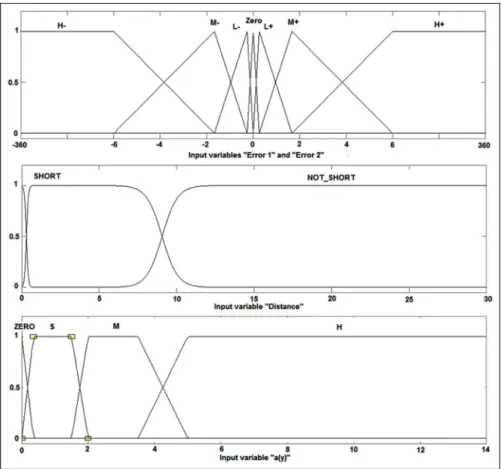
A MF defines how each point in the input space is mapped to a degree of membership from 0 (non-mem-ber) to 1 (full membership). H2 (High negative), M2 (Medium negative), L2 (Low negative), ZERO, H + (High positive), M + (Medium positive), L + (Low positive), RH (Right High), RM (Right Medium), RL (Right Low), NC (No Change), LH (Left High), LM (Left Medium), LL (Left Low) and L/M/H (Absolute Values of Left, Medium and High) are all MFs used either in inputs or outputs of the FIS developed for this study. Each function possesses a degree of membership to which a weighting factor can then be applied depend-ing on the vehicle’s position in relation to the target point, along with the appointed rules.
In a similar manner, MFs for the inputs Error1,
Error2, Distance, Lateral Acceleration a(y) and
Longitudinal Velocityare shown in Figure 4, while the
promising results for most of the problems, triangular MFs were used except theDistanceinput. Thesigmoid
MF was preferred for distance input to provide three interacting but separate areas for three different actions at those parts using just two MFs. On the other hand,
maximum velocity is used to limit the top velocity, and a singleton MF was used to define the limit. Lateral acceleration input was taken as absolute values into the FIS for the purpose of simplicity in fuzzy rule defini-tion, by taking into account the steer angle feedback. Figure 4. MFs of the fuzzy inputs:Error1, Error2, DistanceandLateral Acceleration a(y).
Three basic outputs of the driver must be well syn-chronised to maintain the vehicle’s stability and route. When the process of decision making is considered, it should be as close as possible to human behaviour, and at this point, some criteria should be defined. These cri-teria must include the basic control parameters, realisti-cally, while providing the velocity and steering outputs. For this reason, fuzzy rules as a natural part of the FIS were generated.
Each input should have its own MFs in the FIS structure which should match an output by these gener-ated rules. For instance, steering angle output to be applied depending on the existing situation mostly depends onError1input in the fuzzy rule structure:
If Error1 Zero then Steer Angle is Zero
If Error1 L2then Steer Angle is LR
If Error1 L+ then Steer Angle is LL
If Error1 M2then Steer Angle is MR
If Error1 M+ then Steer Angle is ML
If Error1 H2then Steer Angle is HR
If Error1 H+ then Steer Angle is HL
Error2 input, which represents the secondary target
point, also has a great importance in providing more realistic and satisfactory results from the model. However,Error2 is only taken into account when a cer-tain distance is left to the first target point, in accor-dance with the human driver behaviour. The secondary target point prevents any sudden manoeuvres which may only be the actions of novice drivers. Then, the definition of ‘certain distance’ gains importance. If the action distance to the first target point chosen is rela-tively long, then it may result in too much vehicle decel-eration. If the distance is very short, then the vehicle may traverse and improper velocity changes occur. The correct distance can be found by observing and classi-fying human behaviour. However, dependencies of this distance such as reaction times and psychological situa-tions have not been studied, in detail, during this study. Here, it was decided that the secondary target point may be taken into consideration about in the last 10 m distance to the first target. In this distance, both first and second targets are considered. Therefore, down to 10 m distance, the fuzzy rules related to ‘Error1’ are considered for steering, braking and acceleration out-puts. Then, ‘Error2’ is also used in decision making. If
Error1is too small during the last 10 m to the first
tar-get point, the accelerator will then be depressed to increase the speed. However, a high value of ‘Error2’ is going to decrease the resultant velocity and partly adjust the steering angle to improve the stability while aiming towards the next target. However, for a real driver, making a decision to change the velocity and steering of a vehicle also depends strictly on existing
road conditions and the feel of control. Increasing lat-eral forces encourage the driver to decrease the velocity and/or steer angle if possible for safer handling. Thus, lateral acceleration, as yaw rate and so on, is a factor on decision making of drivers. Therefore, the model
useslateral acceleration a(y) withError1, Error2,
maxi-mum velocityanddistanceas criterions for driver
deci-sion making. In this context, lateral acceleration is classified asZero, Low, MediumandHigh in terms of fuzzy logic. Some selected fuzzy rules representing the roles of the lateral acceleration ‘a(y)’ and ‘Error2’ inputs are given as follows:
If Error1 is Zero, Error2 is M+, Distance is Short
and a(y) is Zero, then Steer Angle is Zero, Accelerator is S and Brake is Zero;
If Error1 is Zero, Error2 is M+, Distance is Short
and a(y) is L, then Steer Angle is Zero and Accelerator and Brake are Zero;
If Error1 is Zero, Error2 is M+, Distance is Short
and a(y) is M, then Steer Angle is Zero and Brake is S;
If Error1 is Zero, Error2 is M+, Distance is Short
and a(y) is H, then Steer Angle is Zero and Brake is M.
In the definition of road coordinates, there may be an infinite number of possibilities. However, in some cases, like long-distance straight-route travel, the coor-dinates, the related fuzzy rules and the base vehicle model must all be well considered due to the possible improper actions of fuzzy driver. For instance, the inputs,Error1, Error2anda(y), can all be zero or near zero representing the straight-route travel. Then, the rules interpret this condition as ‘the velocity can be
increased’, and in this way, there is no limitation in the
rules to limit the velocity. Considering this situation, a limit value may be determined outside the FIS, within the vehicle dynamics model structure. To determine a limit velocity, a fuzzy input, namely, ‘Longitudinal Velocity’, having just a singleton MF, was also intro-duced. When the limit is reached, the condition of sin-gleton MF is satisfied, and Accelerator Pedal input is released while the other cases are also considered. Similar but reverse application is done for deceleration without stopping.
Benchmarking
A benchmarking study was done using a well-known vehicle dynamics simulation tool called IPG CarMakerä. The software package includes also a
normal and aggressive. The defensive driver was used for the simulations due to its closer results to the fuzzy driver model. Some of the comparative actions are pre-sented in Figures 6–9. The comparison shows the single lane-change manoeuvre at 60 km/h initial speed. Steering wheel response shows that IPG driver reacts before the fuzzy driver, and it increases the angle gradually providing a sinusoid with the peaks around 25°–30°. Meanwhile, due to the late reaction of the
fuzzy driver, the angle is increased with a higher accel-eration resulting in higher steering wheel angle for the same route (Figure 6). Figures 7 and 8 show the accel-erator and braking pedal inputs for fuzzy driver and IPG driver, respectively, while Figure 9 compares the longitudinal velocities provided by both the driver models. IPG driver did not use brake pedal during the whole manoeuvre due to slightly decreasing speed. Then, the driver accelerated the vehicle considering the initial speed and the possible reliable drive. Fuzzy driver, on the other hand, increased the speed slightly by continuously caring the route and the velocity. It is
apparent that IPG’s defensive driver was more relax than the fuzzy driver. From the whole responses, the fuzzy driver’s reactions ended with the similar results, however, in a novice manner.
Results and discussions
Path 1/double lane-change manoeuvre
A standard handling test track, which is standardised in ISO 3888-1:1999 (Test track for a severe lane-change
manoeuvre – Part 1: Double lane-change), was used to
test the efficiency of the fuzzy driver/vehicle control model. The trajectory was properly designed to the standard and represented by X and Y coordinates in the model. However, the intention was to observe the performance of fuzzy driver on a standardised path rather than performing a standard test. For the simula-tions, both tyre and vehicle parameters are provided from the literature32
Figure 6. Steering wheel angle responses of IPG driver and fuzzy driver.
Figure 7. Accelerator and braking inputs of fuzzy driver.
Figure 8. Accelerator and braking inputs of IPG driver.
X=½0 0 10 40 50 65 80 105 118 125 130 150 160
Y=[1.057 1.057 1.057 1.057 2.65 4.1 4.642 4.642 2.842 1.75 1.057 1.057 1.057]
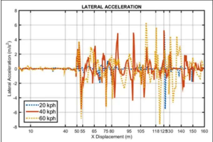
Some of the simulation results for this type of man-oeuvre are shown in Figures 10–12. Simulations were performed at three different initial vehicle speed levels
from 20 to 60 km/h. Figure 10 shows the path followed, while Figures 11 and 12 shows the longitudinal velocity variation and lateral acceleration level provided during the course, respectively. As it can clearly be seen, the velocity of the vehicle is increased up to the first lane-change point and slightly decreased when necessary (between 70 and 80 m distance) to keep the vehicle in position, which is an action provided by the ‘secondary target point’ (peripheral vision) approach. As a result, the manoeuvres are completed highly successfully in the given route. However, the level of slight lateral accel-eration fluctuations, particularly at 60 km/h, shows that the driver tries to keep the vehicle on the ideal course.
Path 2/single lane-change manoeuvre
A lane change and longitudinal travel assessment are also shown in Figures 13–15. Similarly, simulations
were performed at three different vehicle speed levels from 20 to 60 km/h. Figure 13 shows the path followed, Figure 10. ISO 3888-1 manoeuvre (path 1).
Figure 11. Velocity change for path 1.
Figure 12. Lateral acceleration for path 1.
Figure 13. Lane change and longitudinal travel test manoeuvre (path 2).
while Figures 14 and 15 show the longitudinal velocity variation and lateral acceleration level provided during the course, respectively.
As it can also be seen from path 1, in path 2 as well, the driver stabilises the vehicle especially between 80 and 95 m (Figures 14 and 15). At 60 km/h vehicle longi-tudinal velocity, up to 105 m distance, similar response can be observed due to the same path. Afterwards, even if the straight route, driver starts to struggle to keep the line at the same velocity, as seen in Figure 15. Figure 16, on the other hand, presents an example effect of the peripheral vision on vehicle dynamics response. At 40 km/h longitudinal velocity, it is obvious that the input provides better lane keeping and an over-all manoeuvre. Defined vehicle travel coordinates (path 2) are given as follows
X=[0 0 10 40 50 65 80 105 118 125 130 150 160]
Y=[1.057 1.057 1.057 1.057 2.65 4.1 4.642 4.642 4.642 4.642 4.642 4.642 4.642]
Conclusion
In this study, a trajectory following vehicle control model, based on preview control, was developed. Both longitudinal velocity and steering control provided a flexible test environment. The fuzzy controller repre-senting the driver model including peripheral vision approach combined with longitudinal dynamics per-formed well enough in following a prescribed trajectory. However, it is obvious that tuning the MFs well depend-ing on the experience is necessary to increase the robust-ness and reliability of the model, while modelling a human driver is also of importance for the future study.
Declaration of conflicting interests
The author(s) declared no potential conflicts of interest with respect to the research, authorship and/or publication of this article.
Funding
The author(s) received no financial support for the research, authorship and/or publication of this article.
References
1. Renski A. Identification of driver model parameters.Int J Occup Saf Ergo2001; 7: 79–92.
2. Rix JJ and Cole DJ. Models of human learning applicable to the vehicle steering task. In:Proceedings of the 6th inter-national symposium on advanced vehicle control (AVEC 2002), Hiroshima, Japan, 9–13 September 2002, pp.561– 568. http://www2.eng.cam.ac.uk/~djc13/vehicledynamics/ downloads/RixCole_AVEC_2002.pdf
3. MacAdam CC. Understanding and modeling the human driver.Vehicle Syst Dyn2003; 40: 101–134.
4. White D and Thakur K. Stability in the real world-influence of drivers and actual roads on vehicle stability performance(Road transport technology-4). Ann Arbor, MI: University of Michigan Transportation Research Institute, 1995.
5. Sharp RS and Valtetsiotis V. Optimal preview car steer-ing control.Vehicle Syst Dyn2001; 35: 101–117.
6. Sharp RS, Casanova D and Symonds P. A mathemati-cal model for driver steering control, with design, tun-ing and performance results.Vehicle Syst Dyn2000; 33: 289–326.
7. MacAdam CC. Application of an optimal preview con-trol for simulation of closed-loop automobile driving.
IEEE T Syst Man Cyb1981; 11: 393–399.
8. Sharp RS. Driver steering control and a new perspective on car handling qualities. Proc IMechE, Part C: J Mechanical Engineering Science2005; 219: 1041–1051. Figure 16. Lateral accelerations at 40 km/h with and without
peripheral vision.
9. White MC. Measurement and analysis of rally car dynamics at high attitude angles. PhD Thesis, Cranfield University, Cranfield, 2006.
10. Bauer C. A driver-specific maneuver prediction model based on fuzzy logic. Dissertation zur Erlangung der Dok-torwu¨rde urde, Freien Universitat Berlin, Berlin, 2011. 11. Ghaemi S, Khanmohammadi S and Tinati M. Driver’s
behavior modeling using fuzzy logic. Math Probl Eng
2010; 2010: 172878.
12. Plo¨chl M and Edelmann J. Driver models in automobile dynamics application. Vehicle Syst Dyn 2007; 45: 699–741.
13. Hessburg T and Tomizuka M. Fuzzy logic control for lat-eral vehicle guidance.IEEE Contr Syst1994; 14: 55–63. 14. Cheng B and Fujioka T. A hierarchical driver model. In:
Proceedings of the IEEE conference on intelligent transpor-tation system (ITSC ‘97), Boston, MA, 9–12 November 1997. New York: IEEE.
15. Zeyada Y, El-Beheiry EM, El-Araby ME, et al. Driver modeling using fuzzy logic controls for human-in-the-loop vehicle simulations. In: Hassan MF and Megahed SM (eds)Current advances in mechanical design and pro-duction. Oxford: Pergamon Press, 2000, pp.113–122. 16. Mastinu G and Ploechl M.Road and off-road vehicle
sys-tem dynamics handbook. Boca Raton, FL: CRC Press, 2014.
17. Lachenmayr B. Visual field and road traffic. How does peripheral vision function? Ophthalmologe 2006; 103: 373–381.
18. Donges E. A two-level model of driver steering behavior.
Hum Factors1978; 20: 691–707.
19. Day GS and Schoemaker PJH.Peripheral vision: detect-ing the weak signals that will make or break your company. Cambridge, MA: Harvard Business School Press, 2006. 20. Henderson S, Gagnon S, Be´langer A, et al. Near
periph-eral motion detection threshold correlates with self-reported failures of attention in younger and older drivers.
Accident Anal Prev2010; 42: 1189–1194.
21. Castro C.Human factors of visual and cognitive perfor-mance in driving. Boca Raton, FL: CRC Press, 2008. 22. Salvucci D. Modeling driver behavior in a cognitive
architecture.Hum Factors2006; 48: 362–380.
23. Allen RW, Rosenthal TJ and Szostak HT. Steady state and transient analysis of ground vehicle handling. SAE paper 870495, 1987.
24. Allen RW, Rosenthal TJ, Szostak HT, et al.Analytical modelling of driver response in crash avoidance manoeuvr-ing volume II: an interactive model for driver/vehicle simu-lation (US Department of Transportation Report). Washington, DC: US Department of Transportation, 1988.
25. Sahin M.Design and simulation of an ABS for an inte-grated active safety system for road vehicles. MSc Thesis, Middle East Technical University, Ankara, 2007. 26. Precup RE and Hellendoorn H. A survey on industrial
applications of fuzzy control. Comput Ind 2011; 62: 213–226.
27. Dao T-K and Chen C-K. Tuning fuzzy-logic controllers. In: Dadios EP (ed.) Fuzzy logic – controls, concepts, theories and applications. InTech, 2012, http://www. intechopen.com/books/fuzzy-logic-controls-concepts-the-ories-and-applications/tuning-fuzzy-logic-controllers 28. Uzunsoy E and Olatunbosun OA. A generic fuzzy pilot
and path planning for vehicle handling dynamics simula-tion studies (SAE 2003 Transacsimula-tions - journal of passen-ger cars: electronic and electrical systems, p.767). SAE paper 2003-01-2263, 2003.
29. Summala H, Nieminen T and Punto M. Maintaining lane position with peripheral vision during in-vehicle tasks.
Hum Factors1996; 38: 442–451.
30. Olofsson M and Pettersson J.Parameterization and vali-dation of road and driver behavior models for carmaker simulations and transmission HIL-rig. MSc Thesis, Chal-mers University of Technology, Go¨teborg, 2015.
31. CarMaker TM. IPG driver user manual 6.5. Karlsruhe, Germany: IPG Automotive, 2015.