*e-mail: [email protected]
1. Introduction
Among the new materials for applications in power plants, modiied P91 steel has been widely adopted due to its excellent mechanical properties at elevated temperatures, combined with good workability and weldability1-6. As welding is one of the main industrial processes for fabrication of structures and pipelines, the knowledge of residual stress (RS) induced by this process is extremely important because the mechanical properties of the welded components, such as fatigue and thermal fatigue resistance, are not only determined by the microstructures present in the joint, but also by residual stresses heterogeneously introduced in the thermal cycle during the process7,8. In this context, the construction of welding pipelines of high integrity and strength are necessary: in order to achieve safe operation in the power plant, which can be compromised by the presence of residual stresses, which can reach values very close to the material yield strength at determinate regions, decreasing the service life9-11.
Many researches that intended to contribute to better understanding failures that occur in welded modiied P91 steel-pipe are made from the microstructural point of view12-14. In the welding processes some microstructural changes occurring in the joint. The partial transformation of the tempered martensite as well as the partial dissolution of precipitates during the welding thermal cycles result in the regions deined as intercritical (IC) and ine grain (FG) into the heat affected zone (ICHAZ and FGHAZ, respectively). Thus,
these are the most sensitive regions of welded Cr-Mo steels joints, and where, in most cases, the fracture denominated Type IV occurs due to the cumulative creep damage during service life. Recent studies shows that the highest values of tensile residual stresses generated in welding processes, such as GTAW, can be related in the ICHAZ12,15,16.
Despite the high productivity, the Metal Cored Arc Welding (MCAW) and Flux Cored Arc Welding (FCAW) processes are not widely exploited in the manufacture of pipe lines for high temperature17,18. However, still there are few studies about the nature and magnitude of the residual stresses generated by MCAW/FCAW and the inluence of PWHT processes on these stresses and hence the joint properties.
Understanding the distribution, nature and magnitude of the residual stresses may be achieved from experimental measurements, which under common approach, provides the successful design and operation of an industrial installation through different techniques for characterization. Thus, this study aims mainly to evaluate the inluence of PWHT on the residual stresses generated in the MCAW/FCAW welding process in P91 steel by X-ray diffraction technique.
2. Material and Method
In the present work, it was used a P91 seamless pipe in the normalized and tempered condition, with 152 mm outside diameter and a wall thickness of 18 mm. The chemical composition and mechanical properties of the base material are shown in Tables 1 and 2.
Inluence of Heat Treatment in Residual Stresses Generated in P91 Steel-pipe Weld
Tatiane Campos Chuvasa, Pedro Soucasaux Pires Garciab,
Juan Manuel Pardala,b, Maria da Penha Cindra Fonsecaa,b*
aDepartamento de Engenharia Mecânica, Programa de Pós-Graduação em Engenharia Mecânica – PGMEC,
Universidade Federal Fluminense – UFF, Rua Passo da Pátria, 156, Bloco D, Sala 302, São Domingos,CEP 24210-240, Niterói, RJ, Brazil
bPós-Graduação em Montagem Industrial, Universidade Federal Fluminense – UFF,
Rua Passo da Pátria, 156, Bloco D, São Domingos,CEP 24210-240, Niterói, RJ, Brazil
Received: April 6, 2015; Revised: May 18, 2015
The knowledge of residual stress arising from the welding processes is extremely important because the mechanical properties of the welded components are not only determined by the microstructures present in the joint, but also by the heterogeneous residual stresses introduced during the thermal cycle in welding processes. The aim of this work is the characterization of ASTM P91 steel-pipe welded by Metal Cored Arc Welding &Flux Cored Arc Welding (MCAW/FCAW) processes, through the residual stresses evaluation associated with welding and post-weld heat treatment (PWHT). Residual stresses were analysed by X-ray diffraction technique with sin2ψ method, presenting tensile behaviour with higher magnitude at the weld metal of root region. The PWHT promoted the relief of the residual stresses in the both regions. High Vickers microhardness values were observed in the weld metal region before the PWHT, which was very eficient to reduce them.
The samples were welded by the semiautomatic lux cored and metal cored arc welding processes, which are being increasingly applied in tubular joints at site or pipe shop, due to its high productivity.
For the root pass, in order to ensure the maximum integrity of the joint which is provided by electrodes without slag formation, it has been used metallic electrode in the form of a metal cored wire, within the SFA 5:28 speciication and E90C-B9 classiication with 1.2 mm diameter. The illing passes were performed using the E91T1-B9 lux cored electrode that although it produces slag, provides greater productivity to the process when compared to metal cored. The chemical composition of the electrode wires are shown in Tables 3 and 4.
As the shielding gas was used a mixture formed of 98% argon and 2% CO2 with a low rate of 12 l/min. The purge gas used in the root protection against oxidation during welding was commercial argon (99.998% purity) with a low rate of 16 l/min. The API 938-B standard19 requires that the P91 steel be welded at the minimum preheat temperature of 250 °C for greater thickness and interpass temperature between 200 and 300°C. In this work was used preheat temperature of 250 °C and the interpass temperature during welding was about 260 °C and heating was accomplished by electrical resistance, protected by insulating blanket. The sketch with sequence of weld passes is represented in Figure 1.
At each position residual stresses were measured in direction along the pipe axis (axial measurements), in the cap pass and root pass region, by the X-ray diffraction
technique, based on Bragg’s law, using CrKα radiation (λCRKΑ= 2.29092 Å) diffracting the (211) plane for ferrite phase
at 2θ = 156.41°. The stress measurement was performed in the XStress3000 portable analyser with a collimator of 2 mm (30 kV and 6.7 mA), using the sin2ψ method for which the lattice spacing of material were measured at ive ψ-angles between –45° and +45°. Based on a linear regression it, the variations of 2θ versus sin2ψ plots were recorded and the residual stress was evaluated. An accuracy of approximately 15 MPa was achieved using X-ray diffraction.
The access to the root region in a tubular coupon is a major issue in pipe integrity analyses. Thus, this paper presents an analysis of residual stresses in the cap passes and in the root pass of the welded joints using two methods to obtain the samples such as described in Table 5. In addition it was possible to analyse the inluence of cutting process of pipes on the residual stresses.
Table 1. Chemical composition of P91 steel (% weight).
C Si Mn P S Cu Cr Ni
0.108 0.33 0.53 0.013 0.002 0.190 8.560 0.300
Mo V N Al Nb As Sn Ti
0.870 0.221 0.053 0.012 0.067 0.006 0.150 0.003
Table 2. Mechanical properties of P91 steel (room temperature).
σLE(MPa) σLR (MPa) Elongation (%)
ASTM 335 > 415 > 585 > 19
Laboratory 638 724 20
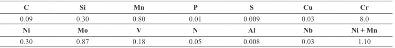
Table 3. Chemical composition of metal cored electrode E90C-B9 (% weight).
C Si Mn P S Cu Cr
0.09 0.30 0.80 0.01 0.009 0.03 8.0
Ni Mo V N Al Nb Ni + Mn
0.30 0.87 0.18 0.05 0.008 0.03 1.10
Figure 1. Sequence of weld passes.
Table 4. Chemical composition of lux cored electrode E91T1-B9 (% weight).
C Si Mn P S Cu Cr
0.11 0.34 0.89 0.020 0.06 0.05 9.4
Ni Mo V N Al Nb Ni + Mn
Firstly the residual stresses from the welding process were measured only in the cap region. After this analysis Sample 1wascut and the residual stresses were measured again. In the root region, due to the small pipe diameter, there was no possibility of carrying out measurements at 90° of the cut. Thus, measurements were performed in two different regions: at 30° and 60° on the half-pipe as shows in Figure 2. Afterward, the PWHT was performed only in the samples 1A and 2A.
Half-pipes were subjected to a heat treatment in an electric furnace where it was heated to a rate of 125°C/h until it was reached a temperature corresponding to 760 °C ± 5 °C, which was maintained for 2 h. The cooling to 250 °C was monitored at a maximum rate of 125 °C/h.
3. Results and Discussion
Initially, the surface residual stresses were measured on the cap in the transverse direction of the bead (axial pipe direction), in order to characterize the state of surface
Figure 2. Schematic representation of welded half-pipe showing location (red point and angles) of residual stresses measurement (a) on the cap; (b) on the root.
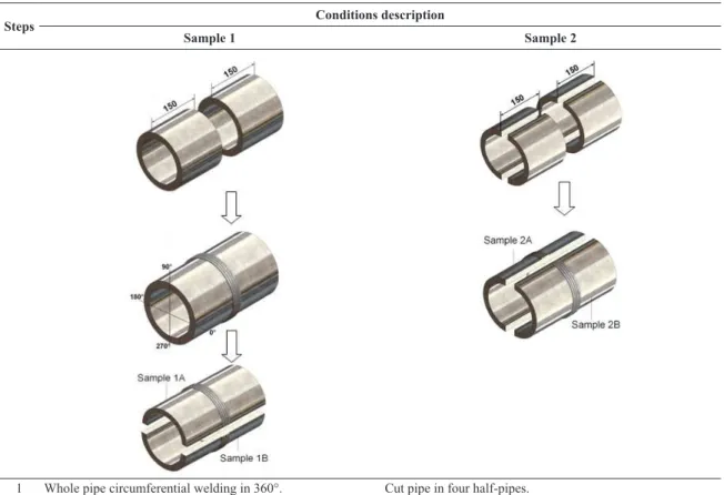
Table 5. Conditions description of the experimental steps.
Steps Conditions description
Sample 1 Sample 2
1 Whole pipe circumferential welding in 360°. Cut pipe in four half-pipes. 2 RS measurement in 2 regions in the cap of welded joint: at 90°
and 270° of the welding start.
Semi-circumferential welding of parts in two half-pipes.
3 Cut in two half-pipes in the region of welding start. RS measurement on the cap and in the root of two half-pipes
welded joint.
4 RS measurement on the cap and in the root of two half-pipes
welded joint. Heat treatment of one half-pipe.
5 Heat treatment of one half-pipe– sample 1A. RS measurement on the cap and in the root of half-pipe heat
treated welded joint – sample 2A.
6 RS measurement on the cap and in the root of half-pipe heat
treated welded joint.
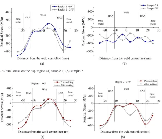
Figure 4. Inluence the cutting process in the residual stresses proile of the sample 1: (a) region 1-90°; (b) region 2-270°.
Figure 3. Residual stress on the cap region (a) sample 1; (b) sample 2.
residual stress after welding of two samples. Each sample shows a very different residual stresses proile (Figure 3), because they were welded by two different methods, with different restriction level as shows in the Table 5. Analysing the proiles for each sample of Figure 3, it is possible to verify the relationship between the nature and the magnitude of these residual stresses and a speciic joint region.
In the welding process preheating and interpass temperature control aims to reduce the thermal gradient between the base metal and the weld metal and decrease the cooling rate between the passes. Thus, occurs the release of hydrogen by effusion, reducing the probability of cold cracks nucleation.
The preheat and interpass temperatures used in the P91 steel welding process should be within the range of martensitic transformation ( and ), ensuring the part of austenite transformation during the welding passes. At the end of the process, when the sample is cooled to room temperature, the martensitic transformation occurs at a lower and controlled cooling rate, resulting in lower levels of the RS. However, the value is critical for the generation of residual stresses. temperature closer to room temperature results in lower residual stresses, because the difference between the phase transformation temperature and the room temperature become smaller and therefore the cooling contraction is minimized. For P91 steels, temperature is about 100 °C, depending on the prior austenite grain size. Thus, the macroscopic contraction stress are minimized and relieved by phase transformation microscopic stresses. In the case of sample 2, welding was
performed on half-pipe, which may have allowed expansion and contraction of the joint during the welding thermal cycle and resulting in compressive residual stresses, as show in Figure 3b. These residual stresses values can be considered beneicial in the context of the fatigue life of the pipe8.
Regarding the sample 1 (Figure 3a), circumferentially welded, the joint restriction results in the higher stress gradients due to differential expansion and contraction of the welding process. Considering that the welding is conducted in several passes, each subsequent pass affects thermally adjacent passes and therefore the residual stresses are the result of these interactions - may occur tempering of the passes, reducing the residual stresses level. As interpass temperatures are controlled, there is a decrease in residual stresses by minimizing thermal gradients involved. However, for the last pass, is expected tensile residual stress because there is no subsequent interaction with other passes and cooling is more abrupt (severe thermal contraction). In fact, the difference in the residual stresses proile is directly related to the welding method and the restriction of the joints. For the sample 1, the circumferential welding resulted in higher joint restriction, which tends to generate tensile residual stresses.
Figure 5. Residual stress located at root after welding on the samples: (a) 1A; (b) 1B; (c) 2A; (d) 2B.
Figure 6. Residual stresses after PWHT (a) cap region and (b) root region. resulting in residual stresses rearrangement. In this case, the tensile nature of the residual stress was changed to compressive. This shows that the welding method and the level of the joints restriction directly inluence on the residual stress proiles.
There are few non-destructive techniques for residual stresses analyses inside of tubular joints and the root region is not commonly studied, even being a region with high incidence of discontinuities. Figure 5 shows that joints presented high magnitude of tensile residual stresses at the root in both regions analysed (up to 400 MPa), which can inluence directly in the cracks nucleation and propagation during the service life. In the root pass was used purge gas, which leads to a more intense cooling rate and results in
less controlled martensitic transformation and more intense cooling contraction, which would explain the high stress values in the two welding methods.
in the joint surface, which would be beneicial during the pipeline service life.
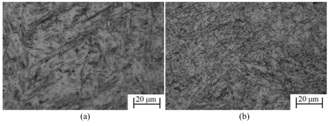
Microstructural analysis showed that base metal (BM) consists of tempered martensite and carbides (Figure 7). In the as-welded sample, the microstructure of the weld metal is
untempered lath martensite (Figure 8a), which explains the high hardness values approaching approximately 450 HV, as shown in Figure 9a and 9b. However, after performing the heat treatment, it shown a microstructure of tempered martensite with high carbide precipitation, as presented in Figure 8b, similar microstructural results are reported by Eggeler et al.20.
The PWHT operation results in a considerable decrease in hardness within the weld metal region (∼260 HV), as shown in Figures 8a and 8b. However, this class of steel has a tendency to form a soft zone in HAZ, speciically in the intercritical HAZ (ICHAZ). This region has only partially austenitised during welding and subsequent PWHT operation produced a relatively soft microstructure, which can reduce the creep resistance of the joint.
In industry it is very common to try to relate hardness values with residual stresses. Based on these proiles presented in the Figure 9 cannot make such a relationship because the nature of the residual stresses is different across regions (root and cap). The results indicated that the microstructure is the preponderant factor inluencing the hardness.
Figure 7. Base metal microstructure.
Figure 8. Weld metal microstructure (a) as welded; (b) after PWHT.
4. Conclusions
This study allows the following conclusions:
1. The welding methods originated different proiles of residual stresses on the welding cap region. On the sample 1 the residual stress proile shows a tensile tendency, particularly during the last pass, however the sample 2 presented high compressive stress average values (–300 MPa). From the above, it can be seen that the method used to obtain the samples inluences the residual stresses proile generated in the same welding process;
2. The analysis of the root region shown high tensile residual stresses values (up to 400 MPa), which could be detrimental to the service life of the component;
3. The post weld heat treatment of 760 °C for 2 h reduced the as-welded residual stresses to a low value, in both root and cap regions;
4. The microstructural analysis of weld metal showed the presence of martensite laths, which after PWHT were transformed into tempered martensite, very close to the base material characteristics, that
believed to contribute to reduce the hardness level of the weld metal region;
5. After welding very high Vickers microhardness values were present in the weld metal region (>400HV) in the cap and root regions. In industry it is very common to try to relate hardness values with residual stresses. Based on these proiles cannot make such a relationship because the nature of the residual stresses is different across regions (root and cap). The results indicated that the microstructure is the preponderant factor inluencing the hardness; and
6. Regarding the soft zone observed in the HAZ, a detailed study of the presented microstructure to reach better conclusions is required. Furthermore, this behaviour is standard for welded joints of P91 steel and these regions are more susceptible to the type VI fracture.
Acknowledgements
The authors would like to thank the Brazilian research agencies (CNPq, CAPES and FAPERJ) for their inancial support.
References
1. Vaillant JC, Vandenberghe B, Hahn B, Heuser H and Jochum C. T/P23, 24, 911 and 92: new grades for advanced coal-fired
power plants - properties and experience. International Journal of Pressure Vessels and Piping. 2008; 85(1-2):38-46. http://
dx.doi.org/10.1016/j.ijpvp.2007.06.011.
2. Narasimhachary SB and Saxena A. Crack growth behavior of 9Cr-1Mo (P91) steel under creep-fatigue conditions.
International Journal of Fatigue. 2013; 56:106-113. http://
dx.doi.org/10.1016/j.ijfatigue.2013.07.006.
3. Maleki S, Zhang Y and Nikbin K. Prediction of creep crack growth properties of P91 parent and welded steel using
remaining failure strain criteria. Engineering Fracture Mechanics. 2010; 77(15):3035-3042. http://dx.doi.org/10.1016/j. engfracmech.2010.04.022.
4. Hyde CJ, Sun W, Hyde TH and Saad AA. Thermo-mechanical fatigue testing and simulation using a viscoplasticity model for a P91 steel. Computational Materials Science. 2012; 56:29-33.
http://dx.doi.org/10.1016/j.commatsci.2012.01.006.
5. Isaac Samuel E and Choudhary BK. Tensile work hardening behaviour of P91 steel. Materials Science and Engineering A. 2011; 528(25-26):7827-7830. http://dx.doi.org/10.1016/j. msea.2011.06.058.
6. Schütze M, Schorr M, Renusch DP, Donchev A and Vossen JPT. The role of alloy composition, environment and stresses for the oxidation resistance of modern 9% Cr steels for fossil
power stations. Materials Research. 2004; 7(1):111-123. http:// dx.doi.org/10.1590/S1516-14392004000100016.
7. Pedrosa PD, Rebello JMA and Cindra Fonseca MP. Residual
stress state behaviour under fatigue loading in duplex stainless steel. Journal of Strain Analysis for Engineering Design. 2011; 46(4):298-303. http://dx.doi.org/10.1177/0309324711400499.
8. Francis JA, Bhadeshia HKDH and Withers PJ. Welding
residual stress in ferritic power plants steels. Materials Science and Technology. 2007; 23(9):1009-1020. http://dx.doi.
org/10.1179/174328407X213116.
9. Yaghi AH, Hyde TH, Becker AA and Sun W. Finite element simulation of residual stresses induced by the dissimilar welding of a P92 steel pipe with weld metal IN625. International Journal of Pressure Vessels and Piping. 2013; 111-112:173-186. http://
dx.doi.org/10.1016/j.ijpvp.2013.07.002.
10. Hilson G, Simandjuntak S, Flewitt PEJ, Hallam KR, Pavier MJ and Smith DJ. Spatial variation of residual stresses in a welded
pipe for high temperature applications. International Journal of Pressure Vessels and Piping. 2009; 86(11):748-756. http://
dx.doi.org/10.1016/j.ijpvp.2009.07.003.
11. Kumar S, Kundu A, Venkata KA, Evans A, Truman CE, Francis JA, et al. Residual stresses in laser welded ASTM A387 Grade
91 steel plate. Materials Science and Engineering A. 2013; 575:160-168. http://dx.doi.org/10.1016/j.msea.2013.03.046.
12. Divya M, Das CR, Albert SK, Goyal S, Ganesh P, Kaul R, et al. Influence of welding process on type IV cracking behavior of P91 steel. Materials Science and Engineering A. 2014; 613:148-158. http://dx.doi.org/10.1016/j.msea.2014.06.089.
13. Arivazhagan B and Vasudevan M. A comparative study on the effect of GTAW processes on the microstructure and mechanical properties of P91 steel weld joints. Journal of Manufacturing Processes. 2014; 16(2):305-311. http://dx.doi.org/10.1016/j.
jmapro.2014.01.003.
14. Allen DJ, Harvey B and Brett SJ. “FOURCRACK”- An investigation of the creep performance of advanced high alloy
steel welds. International Journal of Pressure Vessels and Piping. 2007; 84(1-2):104-113. http://dx.doi.org/10.1016/j.
15. Paddea S, Francis JA, Paradowska AM, Bouchard PJ and Shibli IA. Residual stress distributions in a P91 steel-pipe girth weld
before and after post weld heat treatment. Materials Science and Engineering A. 2012; 534:663-672. http://dx.doi.org/10.1016/j. msea.2011.12.024.
16. Parker J. Factors affecting Type IV creep damage in Grade
91 steel welds. Materials Science and Engineering A. 2013; 578:430-437. http://dx.doi.org/10.1016/j.msea.2013.04.045.
17. Arivazhagan B, Sundaresan S and Kamaraj M. Effect of TIG arc
surface melting process on weld metal toughness of modified
9Cr-1Mo (P91) steel. Materials Letters. 2008; 62(17-18):2817-2820. http://dx.doi.org/10.1016/j.matlet.2008.01.054.
18. Heinze C, Schwenk C and Rethmeier M. Numerical calculation
of residual stress development of multi-pass gas metal arc welding. Journal of Constructional Steel Research. 2012; 72:12-19. http://dx.doi.org/10.1016/j.jcsr.2011.08.011.
19. American Petroleum Institute – API. API Technical Report
938-B: Use of 9Cr-1Mo-V (Grade 91) steel in the oil reining
industry. 1st ed. Washington: API; 2008.