*e-mail: [email protected]
Presented at the International Symposium on High Temperature Corrosion in Energy Related Systems, Angra dos Reis - RJ, September 2002.
Solid Particle Erosion of Plasma Sprayed Ceramic Coatings
José Roberto Tavares Brancoa*, Robert Gansertb, Sanjay Sampathb
Christopher C. Berndtb, Herbert Hermanb
aREDEMAT, (UFOP/CETEC/UEMG)
Av. José Cândido da Silveira, 2000 - Inst. Agronômico Belo Horizonte - M G, Brazil
bCenter for Thermal Spray Research, State University of New York at Stony Brook
NY. USA
Received: September 2, 2002; Revised: September 4, 2002
Thermal spraying allows the production of overlay protective coatings of a great variety of materials, almost without limitations as to its components, phases and constituents on a range of substrates. Wear and corrosion resistant coatings account for significant utilization of ther-mal spray processes. Besides being a means to evaluate the coating tribological performance, erosion testing allows also an assessment of the coating toughness and adhesion. Nevertheless, the relationship between the erosion behavior of thermal sprayed coatings and its microstruc-tural features is not satisfactorily understood yet. This paper examines room temperature solid particle erosion of zirconia and alumina-based ceramic coatings, with different levels of poros-ity and varying microstrucutre and mechanical properties. The erosion tests were carried out by a stream of alumina particles with an average size of 50 µm at 70 m/s, carried by an air jet with impingement angle 90°. The results indicate that current erosion models based on hardness alone cannot account for experimental results, and, that there is a strong relationship between the erosion rate and the porosity.
Keywords:thermal barrier, plasma spraying, erosion
1. Introduction
Plasma sprayed coatings represents a versatile and cost-effective solution for tribological and high temperature cor-rosion applications. The coatings have been commercially used since 1920’s. It is currently possible, by choosing the right feed stock material and coating process, as well as post-processing, to get coatings with performances compa-rable to conventional casting or sintered materials. A major part of thermal spray coatings – TSC - in high temperature applications lacks systematic investigation of their tribological behavior. As a consequence, users and devel-opment engineers can only count on relatively limited em-pirical data, that is little understood.
Solid Particle Erosion, SPE, is a wear process where particles strike against surfaces and promote material loss. During flight a particle carries momentum and kinetic en-ergy, which can be dissipated during impact, due to its in-teraction with a target surface. Different models have been proposed that allow estimations of the stresses that a
mov-ing particle will impose on a target1. The particle will also
be subject to stresses and therefore it can undergo damage. However this possibility is not addressed here. It has been experimentally observed that, during the impact the target can be locally scratched2 extruded3, melted4 and cracked2 in
different ways. The imposed surface damage will vary with the target material, erodent particle, impact angle, erosion time, particle velocity, temperature and atmosphere among others2,5. Erosion rate, defined as the material loss per unit
scale, there are evidences of plastic deformation underneath the target surface. Other evidences suggest that erosion of materials combines ductile and brittle modes simultaneously, the ratio of them depending on impact angle and material properties6-7.
The dynamics of a coating buildup results in a layered structure with individual lamellae oriented differently to the substrate surface, according to the spray angle8,9. Pores can
be seen between and inside lamellae. Brittle lamellae are frequently cracked. Gases adsorbed on the substrate sur-face, fluidity limitations, solidification shrinkage, phase transformation as well as gases trapped in feed stock, pro-mote voids inside TSC. Shrinkage, thermal shock and lin-ear expansion coefficient mismatch between substrate and coating are some of the factors responsible for coating crack-ing. Dimension and content of these features are determined by the spraying process parameters and feedstock material. There is extensive literature on the relationship between mechanical properties of bulk materials and erosion rate. It has been proposed that lateral crack grow from the indenta-tion plastic zone towards the surface originate chips. The erosion scar plastic zone produces the residual stress, which will be the driving force that determines the depth, h, and extent of lateral crack propagation. The lateral crack size being cr, WE, the volume loss per impact, is9:
WE ~ (cr2h)
∝ (1/KnHm) (1)
where n is around 4 and m around 0.25, K and H are the coating toughness and hardness.
In thermal spraying systems, for which there is no spe-cific model has been developed, the study of erosion behavior has been mostly experimental. Variables investi-gated include coating thickness and surface roughness, hard-ness, porosity10. No general trend has been found. The
present authors’ analysis however observed that there are different trends for different coating systems. For example, cermets showed decreased erosion rates with increasing roughness and self-fluxing alloys showed just the opposite. In both systems hardness increased with roughness. Alumina-13Titania had the same erosion rate for average roughness values ranging from 5 to 10 µm. Erosion rates of cermet increased with porosity.
A relationship between erosion wear and coating char-acteristics is not always found11, but in general, one expects
a monotonic decrease of erosion resistance with the increase in porosity11-13. However, there are conflicting data. The
deleterious effect of porosity on erosion resistance has been demonstrated through tribographic features that, for exam-ple, show that the coating crashed around pores14-15. Pores
have been found exposed16-17, which may affect the
effec-tive impact angle that the target sees the erodent. Kawase analyzed Ni-Cr, WC-Co and Alumina data separately and
found that, for the latter two coatings erosion resistance decreased with increase in porosity but no trend could be observed for the Ni-Cr system. There are also reports where investigators did get quantitative erosion and porosity val-ues but they did not present any relationship between them18,19. Data for WC-Ni, showed that, despite porosity
increase with WC content, the erosion resistance and hard-ness increased for carbide contents from zero to 35 wt.% and then both hardness and erosion resistance decreased20.
Porosity effects will depend also on other TSC charac-teristics11-13. Eaton and Novak did find different correlations
between porosity content and erosion rate for coatings of YSZ depending on plasma power. However, by recogniz-ing that different pore structure may have different effects, and using an estimate for a surface area to porosity ratio they were able to find a linear correlation between erosion rate and [(internal surface area/porosity)/bending strength]12.
Mechanical properties of coatings usually include ten-sile strength and hardness, which are proportional. There is still limited data on toughness. Therefore, investigators have searched for relationships between these properties and ero-sion resistance21 and linear correlation between erosion
re-sistance and Tensile Bond Strength, Hardness and Cohe-sion Strength have been reported22. The two latter
proper-ties have been related to one another and their relationship with erosion resistance is reasonable since according to Eq. 1, higher hardness, or equivalent, means higher erosion resistance. Also, the relationship between hardness and po-rosity has been experimentally known in bulk materials23.
However, experimental results on homogeneous materials have shown that hardness alone cannot be used to indicate a general erosion trend, what is also consistent with Eq. 1. It has also been claimed that the effect of toughness in Eq. 1 is underestimated22. As to the effect of adhesion, if just a
small part of the coating is removed during erosion, as men-tioned before, one should not expect that adhesion would influence the wear performance. Yet, there are reports that related high adhesion with high wear performance22.
There-fore, even though one may agree that erosion resistance in-creases with improvement of adhesion, the factors that cause it are still unclear.
In view of the opportunity to better understand the ef-fect of porosity on erosion behavior, this paper examines incremental erosion rates at 90° impact angle and tribogra-phic features of different classes of water stabilized plasma sprayed ceramics.
2. Experimental Procedures
calcia-sta-bilized zirconia (CZ) were sprayed. The AT3 parts were produced by water stabilized plasma, using a WSP PAL 160 system (Institute of Plasma Physics Czech Republic). The AZ and CZ were sprayed with the Plasma Technik PT-2000 system, Table 1. A sample of CZ was tested in the as ground condition, which was accomplished by grinding the as sprayed samples with 600 mesh SiC grinding paper. Room temperature SPE were carried out in a compressed air blasting type rig, under 90° impact angles, according to ASTM G76. The nozzle had a 2.2 mm ID and was kept at 15 mm stand-off distance from the target. 50 µm average
size Al2O3 particles were used as erodent, with an average velocity of 70 m/s, as measured by a stroboscopic Control Vision® system. Weight loss was measured with 0.1 mg variability. Polished cross sections, as well as eroded sur-faces of TSC, were observed under Light and Scanning Elec-tron Microscope. The effect of SPE on the surface rough-ness was measured by profilometry. Porosity was determined using mercury intrusion porosimetry. The flexural strength was determined using 4-point bend testing.
3. Results and Discussion
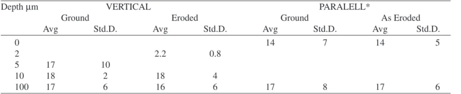
Figure 1a shows schematically a typical incremental
erosion curve and a schematic 2D profile of an erosion scar while in Fig.1b the measured erosion rates are plotted. Ero-sion rates of the reference materials, given in Table 2, fall in the ranges of previous reported values. A transient regime in the erosion process takes place, during which the incre-mental erosion rates decrease monotonically down to a con-stant steady state value. Glass however presented no tran-sient regime. Polishing seems to reduce this trantran-sient re-gime.
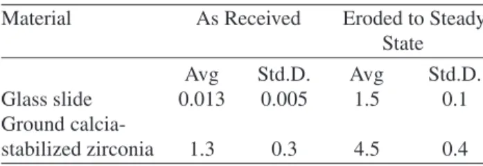
In the tribrographs of eroded WSP free standing CZ, Fig. 2, one can see intersplat boundaries and trans-splat cracked surfaces at various sites. Transgranular cracks are profuse, indicative of brittle erosion mode, and the surface of various pores are exposed. In cross section there is a fine network of cracks, even hundreds of mm away from the eroded edge, Fig. 3. The average intercrack distance in both vertical and parallel directions, relatively to the coating-substrate interface, were measured at various distances from the eroded surface of ground CZ, Table 3. It is clear that grit blasting imposes a significant increase in the density of ver-tical cracks.
The decrease in the wear rate with erosion time (or erodent dose) has been reported before24. They postulated
that, for some brittle materials, initially the target surface is thoroughly cracked with minimum material loss. Then,
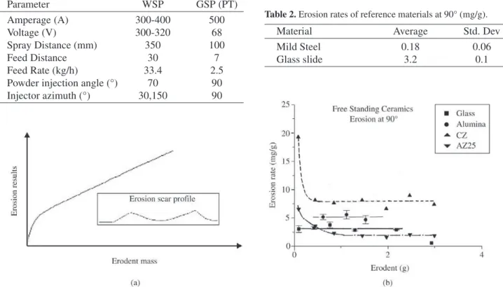
sig-Table 1. Spray parameters.
Parameter WSP GSP (PT)
Amperage (A) 300-400 500
Voltage (V) 300-320 68
Spray Distance (mm) 350 100
Feed Distance 30 7
Feed Rate (kg/h) 33.4 2.5
Powder injection angle (°) 70 90
Injector azimuth (°) 30,150 90
Table 2. Erosion rates of reference materials at 90° (mg/g).
Material Average Std. Dev
Mild Steel 0.18 0.06
Glass slide 3.2 0.1
nificant chipping occurs, which leads to a maximum ero-sion rate. Further particle impact cracking proceeds, with less material removal. Later, Levy proposed that incremen-tal erosion rate curves of brittle materials start with a high rate at the first measurable amount of erosion and that it then decreases to a much lower steady state value25. This is
more reasonable. The maximum values reported for refer-ence brittle material, NiO scale, was a result of three effects interaction: NiO scale, porous NiO and Ni and therefore should not be expected to occur on single TSC. The soda-lime glass, which has a brittle behavior under the condi-tions used for this work, showed neither a maximum nor a monotonic decay in the incremental erosion rate. In another analysis, high surface roughness was suggested to be the responsible factor for high initial erosion rate of TSC26,
where protrusions are easily knocked out from as sprayed surface. Polishing TS zirconia with 1 µm alumina decreased
the initial incremental erosion rate and did not alter the steady state erosion rate. Nevertheless, the material still exhibited
a monotonically decreasing incremental erosion rate curve. This finding was also verified in the present work. Also, the roughness of the polished coating, which was much less
Figure 2. Tribography of CSZ sample, in eroded condition: a) 50 µm; b) 10 µm, marks.
Figure 3. Cross section of a representative coating after erosion test. Cracks in the vertical (V) and parallel (P) direction are indi-cated.
Table 3. Inter-crack distance at different depths in the eroded coating of calcium stabilized zirconia (µm).
Depth µm VERTICAL PARALELL*
Ground Eroded Ground As Eroded
Avg Std.D. Avg Std.D. Avg Std.D. Avg Std.D.
0 14 7 14 5
2 2.2 0.8
5 17 10
10 18 2 18 4
100 17 6 16 6 17 8 17 6
Avg = average value; Std.D. = Standard deviation.
than in the as sprayed condition, significantly increased af-ter erosion, a result also verified in this work, Table 4. The eroded surface profile changes but the average roughness does not change significantly. Considering a cross section of the as sprayed surface, there is a superposition of two waves: one with wave length on the order of 100 µm and
the other with a wave length on the order of 1 to 10 µm.
Most likely the high wavelength reflects the splat size and the short wavelength reflects either splashing of the liquid particles upon impact on the substrate surface or unmelted particles. These fine protusion-like coating parts are rela-tively loose and can be removed with less energy than what would be necessary to remove a similar part from the bulk of the coating. Consequently, during the transient erosion regime, there is a smoothened of the coating surface.
Some insight on the reasons for the SPE transient as observed in this work can come from the current modeling of brittle erosion. According to it, debris are created due to
lateral cracking and intersection between various crack types. The size of these cracks varies with load, or equiva-lently, impact energy. If one start a SPE experiment with a target that has a cracking structure with dimensions lower than expected for the impact energy to be used, the incre-mental erosion rate should increase as the cracking dimen-sions increase up to a steady state. If, on the other hand, the cracking dimensions and density are higher than what would be imposed by the experiment impact energy, then the ero-sion rate should start high and decrease to a steady state value, as the cracking dimensions and density decrease. This proposition has actually been demonstrated previously27. In
the case of TSC, it is possible that the near surface coating has a defect density higher than the bulk coating. With higher crack density the near surface coating toughness decreases and so does hardness, which, according to Eq. 1 should deter-mine a higher erosion rate than the bulk coating. Also, since solid particle impact can promote significant surface heating, it is possible that crack closing happens during erosion.
The present results confirm that various tribographic features found in monolithic materials are present in TSC, more so in the high cohesion and low porosity coatings. However, significant differences exist and are related with the as sprayed surface and coating microstructure. Previous expectations that brittle thermal sprayed coatings erode by cracking and chipping mechanism, can than be just partially met28. Even results for steady state erosion rates vs. impact
angle for NiCrAlY at room temperature, have shown that this coating had the same erosion rate at 30 and 9029, which
denotes brittleness in the coating. Similar results found that thermal sprayed metals eroded in brittle manner30. Table 4. Average Roughness of erosion coupons (µm).
Material As Received Eroded to Steady State
Avg Std.D. Avg Std.D.
Glass slide 0.013 0.005 1.5 0.1
Ground
calcia-stabilized zirconia 1.3 0.3 4.5 0.4
Avg = average value Std.D. = Standard deviation
Figure 4 shows the erosion rate and the rupture modu-lus as a function of porosity content. As the rupture strength decreases, one should expect that the role of intersplat decohesion should increase and the material loss per im-pact event should also increases, increasing the erosion rate. However, despite the fact that the coatings have very different mechanical properties at the same porosity con-tent, it is the porosity that dictates the erosion behavior. This result shows that there must be a strong microstruc-tural feature to be incorporated in erosion models. Poros-ity is definitely one very important feature, which influ-ences erosion in three ways. Firstly, it decreases the mate-rial’s strength against plastic deformation or chipping , since the material at the edge of a void lacks mechanical support. Secondly, the concave surface inside a void, that is not under the shadow of some void edge, will see an impinging particle at an angle higher than the average tar-get surface to impact angle. This will be detrimental for brittle materials and beneficial for ductile ones. Finally, pores can act as stress concentrators and decrease the load-bearing surface.
4. Conclusion
High cohesion and low porosity coatings tend to be dam-aged by the same mechanisms as cast and sintered materi-als. The effect of porosity is significant and needs to be accounted for in erosion wear modeling. When there is high porosity content at intersplat surfaces, its effect is superim-posed in the cohesion effect. Otherwise, porosity will influ-ence erosion in three ways. Firstly, it decreases the materi-als strength against plastic deformation or chipping since, the material at the edge of a void lacks mechanical support. Secondly, the concave surface inside a void, that is not un-der the shadow of some void edge, will see an impinging particle at an angle higher than the average target surface to impact angle. This will be detrimental for brittle materials and beneficial for ductile ones. Finally, pores can impair strength. They do so by acting as stress concentrators and/ or decreasing the load-bearing surface.
Acknowledgment
The authors are grateful for the support granted by Conselho Nacional de Desenvolvimento Científico e Tecnológico – CNPq and CETEC.
References
1. Angel, P.A. Impact Wear of Materials. (Elsevier: New York, 1976).
2. Tilly, G.P. “Erosion Caused by Impact of Solid Parti-cles”, in H. Herman (ed), Treatise on Materials Science and Technology, vol. 13: D. Scott (ed), Wear. (Academic
Press: New York, 1979) p.287-320.
3. Erosion by Liquid and Solid Impact. (Cavendish Labo-ratory, University of Cambridge: Cambridge, England, 1979).
4. Erosion by Liquid and Solid Impact. (Cavendish Labo-ratory, University of Cambridge: Cambridge, England, 1987).
5. Evans, A.G. “Impact Damage Mechanism - Solid Projec-tile”, in H. Herman (ed.), Treatise on Materials Science and Technology, Vol. 16: C.M. Preece (ed.), Materials Ero-sion, (Academic Press: New York, 1979), p. 1-67. 6. Eyre, T.S. Wear Resistance of Metals”, in H. Herman
(ed), Treatise on Materials Science and Technology, vol. 13: D. Scott (ed), Wear. (Academic Press: New York, 1979), p. 363-442.
7. ASM HANDBOOK, vol. 18: Friction, Lubrication and Wear.
8. Hutchings, I.M.; Winter., R.E. J. Phus. D Appl. Phys., v. 8, p. 8-14, 1975.
9. Ives, L.K.; Ruff, A.W. Wear, v. 46, p. 149-162, 1978. 10. Tilly, G.P. Wear, v. 14, p. 63-79, 1969.
11. Smeltzer, C.E.; Gulden, M.E.; Compton, W.A. Jnl. Ba-sic Eng., v. 92D, n. 139, 1970.
12. Hockey, B.J.; Wiederhorn, S.M. Erosion of Ceramic Materials: The Role of Plastic Flow, paper 26 in ref. 3. 13. Hockey, B.J.; Wiederhorn, S.M.; Johson, H. in (R.C. Bradt, D.P.H. Hasselman and F.F. Lange, eds.) Frac-ture Mechanics of Ceramics - 3, Flaws and Testing (Ple-num Press: New York, 1978) p. 379.
14. Stringer, J.; Wright, I.G. Some Views on the Formation fo Ripples on Eroded Surfaces, paper 47 in ref. 4. 15. Finnie, Kabil, Y.H. Wear, v. 8, p. 60-69, 1965. 16. Davis, A.G.; Boone, D.H.; Levy, A.V. Erosion of
Ce-ramic Thermal Barrier coatings, Wear, v. 110, p. 101-116, 1986.
17. Rogers, P.M.; Shipway, P.H.; Hutchings, I.M.;Little, J.A. The erosion-corrosion of plasma-sprayed alumina coat-ings on a Low Chromium Steel, paper 35 in A.V. Levy (ed.), C-E. Wear of Materials at Elevated Temperature, 1990.
18. Levy, A.V. The platelet mechanism of erosion of duc-tile metals, Wear, v. 108, p. 1-21, 1986.
19. Levy, A.V.; Aghazadeh, M.; Hickey, G. “The effect of test variables on the Platelet mechanism of erosion”, Wear, v. 108, p. 23-41, 1986.
Nacional de Desenvolvimento Científico e Tecnológico. 1995
23. Hardness and porosity in sinterred materials: Kirillov , V.S. et al., Sov. J. Superhard Materials, v. 5, n. 21, 1983. 24. Levy, A.V. The erosion-corrosion behavior of protec-tive coatings, Surf. and Coat. Techn., v. 36, p. 387-406, 1988.
25. Wright, I.G.; Shetty, D.K. A Phenomenological Ap-proach to Modelling the Erosion of WC-Co Alloys,.. 7th ELSI, paper 43.
26. Pennefather, R.C.; Hutchings, R.; Bull, A. Erosion mechisms in Cemented Carbides Subjected to Solid
Particle Erosion, paper 60 in ref. 3.
27. Scattergood, R.O.; Roubort, J.L.; Transient and Synergistic Effects in Solid-Particle Erosion of Silicon, JACS, C-104, 1981.
28. Levy, A.V. The Erosion-Corrosion Behavior of Protec-tive Coatings, Surface and Coatings Technology, v. 36, p. 387-406, 1988.
29. Wang, B.Q.; Geng, G.Q.; Levy, A.V. Erosion-Corro-sion of Thermal Spray Coatings, Surface and Coatings Techn., v. 43/44, p. 859-874, 1990.