IEEE Proof
Web Version
IEEE TRANSACTIONS ON ANTENNAS AND PROPAGATION, VOL. 61, NO. 1, JANUARY 2013 1
Hybrid UHF/UWB Antenna for Passive Indoor
Identification and Localization Systems
Catarina C. Cruz, Jorge R. Costa, Senior Member, IEEE, and Carlos A. Fernandes, Senior Member, IEEE
Abstract—There is a growing interest for simultaneous
identifi-cation and centimetre-resolution localization of multiple targets in indoor environments. A hybrid passive UHF/UWB RFID concept has been recently proposed that conciliates the potential from high resolution UWB impulse radio with the typical range from UHF-RFID identification systems. This paper proposes a new planar an-tenna for hybrid passive tag systems, which operates both in the UHF-RFID band and in the FCC UWB band. The co-designed UHF and UWB antenna elements are printed back-to-back on each side of a common substrate with appropriate topology for future integration with a single UHF-UWB RFID chip. Experimental tests have shown that both UHF-RFID and UWB performance of the hybrid antenna are comparable to available commercial solutions that work just on a single band. The antenna is adequate for low-cost mass production of hybrid passive tags. It aims at low-low-cost pas-sive RFID systems combining the ability of item identification with precise tracking in indoor environments.
Index Terms—Indoor localization and identification, passive tag
antenna, dual-band antenna, RFID, UWB. I. INTRODUCTION
T
HERE is a high demand for reliable and accurate indoor real-time identification and tracking of persons and/or ob-jects, where satellite-based services fail. The growing market of Real-Time Location Systems (RTLS) is expected to reach 2700 million US dollars in 2016 [1] yet most of the available com-mercial solutions are still not 100% reliable [2] and have high associated costs.Usual indoor RTLS are based on optical, infrared, ultra-sounds, radio frequency or a combination of these technolo-gies. Optical and infrared systems are very accurate but require line of sight [3]. Ultrasounds are also highly accurate but they are susceptible to environment noise [4]. Hybrid systems combining optical imaging with infrared and ultrasound have been widely explored for example in gamepads for the general public. Although the accuracy of these systems is generally very good, the major limitation is the number of objects that can be simultaneously tracked, especially when they obstruct each Manuscript received February 11, 2012; revised July 15, 2012; accepted Au-gust 20, 2012. Date of publication September 21, 2012; date of current ver-sion December 28, 2012. This work was supported in part by Fundação para a Ciência e Tecnologia under Project RFIDLocal PTDC/EEA-TEL/102390/2008. C. C. Cruz, J. R. Costa and C. A. Fernandes are with Instituto de Telecomu-nicações, Instituto Superior Técnico, Technical University of Lisbon, 1049-001 Lisboa, Portugal (e-mail: [email protected]).
J. R. Costa is also with Instituto Universitário de Lisboa (ISCTE-IUL), Depar-tamento de Ciências e Tecnologias da Informação, 1649-026 Lisboa, Portugal. Color versions of one or more of the figures in this paper are available online at http://ieeexplore.ieee.org.
Digital Object Identifier 10.1109/TAP.2012.2220112
other. Even more critical is the fact that unique identification is not possible in general.
Radio frequency RTLS can overcome this limitation by pro-viding unique identification of the object and in some cases also the location, although generally with less accuracy than the pre-viously described systems. The most common radio frequency RTLS are based on RFID or UWB technologies [5].
Current commercial RFID systems are designed for item identification only, but they can still be used for coarse posi-tioning. In one common approach, coarse tag positioning is obtained by comparing its received signal strength (RSS) with the RSS from neighboring tags located in pre-defined positions [6]. Accuracies are in the order of 1 m, limited by RSS strong dependence on the environment and tag orientation [7], [8]. In a different perspective, RFID reader antennas can be designed to self-delimit a near-field detection zone, enabling selective identification of only those objects that are placed above a given shelf [9], on a conveyor belt [10] or in front of a mirror [11]. Despite the lower resolution from RFID based RTLS, this is one of the cheapest solutions per item, especially when using battery-less (or passive) tags. Passive tags do not require maintenance and its unit cost for the UHF band is expected to reach 0.05 US dollars between 2014 and 2016 [12].
In UWB localization systems, distance to the target is obtained from time-of-arrival (ToA) of sub-nanosecond trans-mitted pulses. These systems typically achieve centimeter resolution [1]. Regulations for UWB authorize unlicensed use of 3.1 to 10.6 GHz spectrum in US [13] and 6 to 8.5 GHz in Europe [14], subject to a spectral power density limit of dBm/MHz. This ensures spectrum sharing with other estab-lished narrowband applications without mutual interference, but at the same time it implies a severe range limitation. UWB systems are highly immune to multipath interference, have low power consumption and involve low complexity transceivers since baseband transmission is used. Commercial UWB lo-calization solutions already exist based upon active tags [15], [16]. However, passive UWB tag solutions would be more at-tractive for low-cost, maintenance-free large-scale deployment applications, if the range limitation could be overcome. In fact, regulation compliant ultra-wideband pulses are insufficient to energize passive tag’s chips, unlike what is done in UHF RFID. An alternative approach has been presented in [17] where a narrowband continuous wave UHF RFID signal is broadcast by the reader, which carries the clock, commands, and energy to power-up the chip on the tag, whereas it responds with UWB pulses. The feasibility of the UHF/UWB hybrid concept is demonstrated in [18] using a breadboard circuit with discrete components and well separated UWB and UHF antennas to 0018-926X/$31.00 © 2012 IEEE
IEEE Proof
Web Version
avoid mutual influence. This large circuit is not practical for real applications. In [19] a UHF/UWB hybrid chip is developed with on-chip UHF and UWB antennas each one connected to the respective port. The solution is very compact with a few mm square, but the downside is the achievable range of only 7 cm because of insufficient on-chip antenna size. This motivates the development in the present work of a single external efficient antenna with two independent ports (for the UHF and UWB), located close enough to be compatible with a single chip similar to the one in [19] to boost the system range. The fundamental requirement for the antenna design is its simultaneous operation at UHF and in the FCC UWB band, with best possible pulse preservation for accurate estimation of ToA. The antenna is also required to be compact, lightweight and low-cost.
This paper is organized in four sections. The antenna design is described in Section II. The performance of a prototype is presented in Section III. Numerical and experimental RFID de-tection and ranging results are given and discussed throughout. Conclusions are finally drawn in Section IV.
II. ANTENNADESIGN
The schematic of the developed hybrid UHF-UWB antenna is presented in Fig. 1. It is a planar antenna comprising two metallic layers printed on each side of a
mm thick Duroid 5880 substrate with permittivity and loss tangent . One of the printed layers corre-sponds to the UHF radiating element and the other to the UWB element. The UHF element is based on a meandered line plus loop, while the UWB is a modified version of the Crossed Ex-ponential Tapered Slot antenna (XETS) proposed in [20], [21] which was shown to present excellent transient performance for the full UWB band. As will be explained ahead, one of the chal-lenges is to design and arrange the UHF and UWB elements in a way that minimizes mutual influence. Furthermore, the two elements are aligned so that the feeding ports almost overlap at each side of the substrate, see Fig. 1. In this way, a single hybrid RFID-UWB chip can be used to connect its ports directly and through vias to the antenna ports. Actually such hybrid IC chip is not yet available commercially, although a similar one has been demonstrated in [19] for on-chip antennas. Therefore, in order to design and test the antenna, it is assumed that the hybrid chip will present a differential port for UWB with 50 input impedance. For the UHF port, it is assumed that the chip will present the input impedance of current commercial UHF RFID ICs. The antenna is designed considering the input impedance
of the ALIEN Higgs-2 IC which is [22],
which is available at our lab for integration and test. Alternative chips can be easily accommodated in the design.
A. RFID Chip Characterization
Since the RFID chip on the UHF side of the substrate is di-rectly on top of the UWB terminals on the other face of the tenna, the chip is expected to influence as well the UWB an-tenna impedance and radiation performance. Thus, it is essen-tial to obtain a lumped model describing the chip behavior for both bands, to be used in the electromagnetic solver. The chip manufacturer provides a lumped model only for the UHF band,
Fig. 1. Exploded view of the hybrid RFID-UWB antenna showing the two met-alized faces from each side of a common planar substrate.
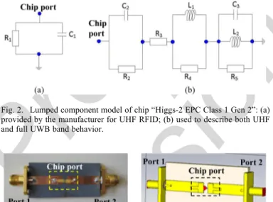
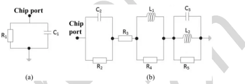
Fig. 2. Lumped component model of chip “Higgs-2 EPC Class 1 Gen 2”: (a) provided by the manufacturer for UHF RFID; (b) used to describe both UHF and full UWB band behavior.
Fig. 3. Microstrip test line with RFID chip at half-length: (a) fabricated proto-type; (b) simulation model in CST.
a parallel between a 1500 resistor and a 1.2 pF capacitor, see Fig. 2(a). This is not enough to model the chip for the full FCC UWB band.
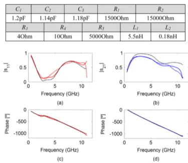
A procedure that combines simulated and measured results is used to de-embed the RFID chip impedance up to 10.6 GHz. Two test circuits were manufactured: a reference circuit corre-sponding to a straight 50 microstrip line and a second circuit with a microstrip line with the same dimensions but with a gap at half length, loaded at that point with the chip under test, see Fig. 3. Both circuits are replicated in the CST Microwave Studio [23], where the RFID chip is modeled by a lumped circuit, Fig. 2(b). The lumped model parameters are adjusted to max-imize the correlation between measured and simulated curves of and versus frequency. Table I presents the final com-ponent values.
Fig. 4 compares magnitude and phase of measured and sim-ulated and curves, using either the manufacturer UHF model or the proposed extended model.
Fig. 4 confirms that the manufacturer model agrees with the measured curves for UHF ( GHz). However, only the new model agrees well for the extended band, namely for high mag-nitude values of from 2 to 6 GHz. The extended model is
IEEE Proof
Web Version
CRUZ et al.: HYBRID UHF/UWB ANTENNA FOR PASSIVE INDOOR IDENTIFICATION AND LOCALIZATION SYSTEMS 3
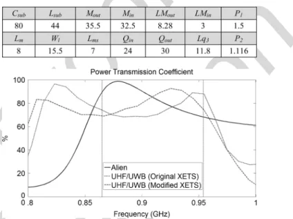
TABLE I
COMPONENTVALUES FOR THELUMPEDELEMENTMODELS OF THECHIP
Fig. 4. Magnitude ((a) and (b)) and phase ((c) and (d)) for s11 and s21, respec-tively, measured ( ) and simulated ( ) using the proposed extended model for both UHF and UWB bands and using the manufacturer model (ALIEN) ( ).
used throughout in CST for the co-design of the UHF and UWB radiating elements.
B. Design of the RFID Part of the Antenna
Design and performance of the RFID part of the hybrid an-tenna are affected by the presence of the XETS on the other face of the substrate, and vice-versa. By choosing an appropriate ori-entation and alignment of the two radiating elements at each side of the substrate, to be detailed ahead, it is possible to minimize its mutual influence. At a first step of the UHF element opti-mization, a previous XETS design is used on the other face of the substrate, loaded with 50 at its port.
The geometry of the UHF-RFID element in Fig. 5 shows a double loop connected to a meandered dipole. Since UHF and UWB ports must be close in the xy-plane as explained, two mi-crostrip lines are used inside the loop to connect the UHF RFID chip at the center. The lines are very narrow (0.4 mm) and posi-tioned in a way that minimizes the interference with the XETS antenna on the opposite side.
The antenna RFID port impedance must equal the complex conjugate of the chip impedance, for maximum power transfer: at 860 MHz. Thus, the antenna impedance must exhibit inductive behavior, which is achieved using the loop. The adopted double-loop configuration en-hances bandwidth compared to a single loop [24]. The loop itself presents insignificant real part of the impedance, so the radiating behavior is obtained with the addition of a dipole, which is meandered to reduce its length.
The described UHF-RFID element is optimized to operate for the three geographic worldwide region sub-bands: 865–868 MHz for Europe, 902–928 MHz for U.S. and 952–954 MHz for Japan. The obtained parameter values are given in Table II.
Fig. 5. Geometry of the RFID face of the hybrid antenna, designed with CST Microwave Studio.
TABLE II
PARAMETERVALUES OF THERFID FACE INMILLIMETERS
Fig. 6. Simulated Power Transmission Coefficient for the proposed hybrid an-tenna and for ALIENS’s Squiggle tag.
It makes sense to analyze the power transfer coefficient from the antenna to the chip, as this relates directly to the tag achievable range. It measures the maximum fraction of the available power at the antenna port that is transferred to the chip [25]. The simulated result is presented in Fig. 6 (dotted green curve). Power transmission is above 70% level across the entire UHF band (from 860 MHz to 960 MHz). Superimposed on Fig. 6 is the transmission coefficient for the commercial tag ALN-9640 Squiggle Alien [22] that uses the same RFID chip (solid blue curve). It is noted that the hybrid tag presents com-parable performance within the UHF-RFID band, though with marginally lower power transfer values. This will be improved at a later stage of the hybrid antenna design, as detailed ahead.
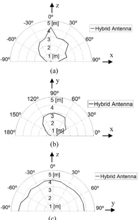
Fig. 7 shows the simulated radiation pattern at 866 MHz. The hybrid antenna presents at UHF-RFID a typical dipole-like ra-diation pattern. Similar behavior is observed across the whole UHF-RFID band.
C. Design of the UWB Part of the Antenna
The XETS element used on the UWB face of the antenna (Fig. 8) derives from the original version demonstrated by the authors in [20], [21] for the full FCC UWB band (3.1 GHz to
IEEE Proof
Web Version
Fig. 7. Simulated UHF-RFID far-field radiation pattern at 866 MHz.Fig. 8. Parameters defining the UWB face of the hybrid antenna [20]: (a) single exponentially tapered slot; (b) star slot.
Fig. 9. Representative scheme of the orientation of the two overlapping faces of the hybrid antenna considering a transparent substrate.
10.6 GHz). This antenna has stable radiation pattern, well de-fined linear polarization and very well dede-fined constant phase center versus frequency.
Some modifications of the original XETS configuration are however necessary for integration into the hybrid antenna. It is reduced to a single metallization layer and the feeding is done directly at the XETS front face. As in [20], [21], a thin semi-rigid coaxial cable EZ-41 (1.19 mm diameter), is used for that (Fig. 9).
As in the previous Section, the optimization of the UWB an-tenna shape parameters is performed with the UHF anan-tenna on the other side, loaded by the RFID chip model from Section II.A. Table III summarizes the obtained XETS parameter values pre-sented in Fig. 8 and keeping the same nomenclature from [20].
Fig. 10. Hybrid antenna prototype: (a) UWB face; (b) RFID face.
Fig. 11. Setup for measuring RFID range inside the anechoic chamber.
The slot exponential geometry is given by the width at the slot longitudinal coordinate measured from the centre of the slot, see Fig. 8. Slot width at the centre is is the exponen-tial expansion parameter and is the antenna thickness. Simu-lated VSWR curve and radiation pattern are shown in Figs. 13, 14 and 15 with experimental results.
This change in the XETS shape influences the previously designed UHF-RFID element performance. Fig. 6 shows the corresponding power transfer coefficient after replacing the XETS by the modified one (dashed red curve): actually the power transfer characteristic improves, becoming much similar to Squiggle’s. Thus, no further iteration of the design process is required.
III. ANTENNAEXPERIMENTALPERFORMANCE Fig. 10 shows both faces of the manufactured prototype. The coaxial cable is connected between two opposed petals from the UWB antenna (Fig. 10(a)) and the RFID chip is soldered at the UHF port (Fig. 10(b)). Corresponding experimental RFID detection and UWB ranging performance is analyzed next.
A. RFID Performance
The RFID reading range of the hybrid antenna is evaluated in-side an anechoic chamber. For this purpose, the antenna under test is attached to an azimuth positioner, with due care to avoid unwanted reflections from antenna back lobe. The RFID reader antenna is attached to a tripod and pointed to the center of the hybrid antenna. For each azimuth orientation of the hybrid an-tenna (at 15 steps of the azimuth positioner), the tripod travels
IEEE Proof
Web Version
CRUZ et al.: HYBRID UHF/UWB ANTENNA FOR PASSIVE INDOOR IDENTIFICATION AND LOCALIZATION SYSTEMS 5
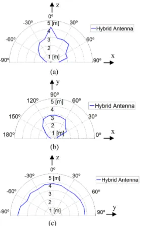
Fig. 12. Polar RFID detection range charts for the hybrid antenna at the planes: (a) E1 (xz plane); (b) E2 (xy plane); (c) H (yz plane).
Fig. 13. Measured and simulated VSWR curve of UWB port of the hybrid antenna with a RFID chip placed in the RFID port.
along the link direct path to determine the corresponding edge of the RFID detection region.
Commercial circular polarized antenna ALR-8610-AC and ALR-8800 Enterprise Scalable RFID Reader from ALIEN are used in these tests. Its power is adjusted to limit detection to the maximum measurable distance inside the anechoic chamber (4 m). Results for the antenna main planes are presented in Fig. 12. The z-axis (plane-E1) and y-axis (plane-E2) correspond to face-to-face alignment of tag and reader antenna (Fig. 11). The results are consistent with the radiation pattern from Fig. 7, resembling a dipole radiation pattern with nulls along the x-axis (dipole axis).
The same test is repeated for the commercial ALIEN ALN-9640 Squiggle passive tag [22] that uses the same RFID chip.
Fig. 14. Measured ( ) and ( ) and simulated ( ) and ( ) radiation patterns at GHz: (a) plane-1 magnitude; (b) plane-2 mag-nitude; (c) plane-1 phase; (d) plane-2 phase.
Obtained results are practically coincident with the hybrid an-tenna results, also with a maximum range of about 4 m. If max-imum allowed reader power is used in open space, both tags are detected up to 8 m distance. Tests show that the RFID perfor-mance of the proposed hybrid antenna tag is comparable to the performance of a standard commercial passive tag. However, as will be demonstrated next, the developed antenna further op-erates simultaneously in the FCC UWB band, which is not the case of available commercial RFID tags.
B. UWB Performance
Measured VSWR of the hybrid antenna is superimposed on simulations in Fig. 13. There is a good match between measured and simulated curves across the FCC UWB band, with values mostly below 2. Although VSWR of the UWB antenna degrades near the edges of the UWB band, this does not compromise localization performance for impulse-based systems. The used pulse is identical to the one presented in [20], (5). It is defined by
(1) where the central frequency is GHz in order to center the pulse spectrum within the UWB band and the Gaussian width is ps to comply with the FCC indoor spec-trum mask. In fact the pulse specspec-trum decreases significantly near the edges of the UWB band. Therefore, the pulse shape is not affected by the slight restriction of the operation band at the edges. Pulse fidelity, [26] which quantifies the pulse preserva-tion performance of the antenna is 95% in the main direcpreserva-tion.
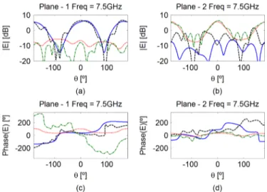
Measured radiation patterns are shown in Figs. 14 and 15 at 5 GHz and 7.5 GHz, respectively, superimposed on the CST simu-lated curves. The same figures present the absolute gain: it is 3.4 dBi at 5 GHz and 6.1 dBi at 7.5 GHz. These values are similar to those previously obtained for the stand-alone UWB antenna described in [20] which was characterized between 3.1 and 10.6 GHz. Unlike the original XETS [20], [21], the presence of UHF part of the hybrid antenna precludes a stable and well-defined polarization in the UWB band. However, this does not prevent
IEEE Proof
Web Version
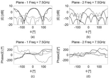
Fig. 15. Measured ( ) and ( ) and simulated ( ) and( ) radiation patterns at .5 GHz: (a) plane-1 magnitude; (b) plane-2 magnitude; (c) plane-1 phase; (d) plane-2 phase.
TABLE III
PARAMETERVALUES OF THEXETS ANTENNA INmm
good positioning accuracy as will be discussed ahead. Measured phase pattern is almost horizontal within the main lobe, as seen in (c) and (d) plots from Figs. 14 and 15. It indicates that the an-tenna phase center position is constant, near its geometric center in both planes and both frequencies, a fundamental character-istic to preserve the pulse shape.
C. Localization Performance
The final goal of the design of this antenna is its integration with an identification and localization system. Therefore indoor localization trials are performed to determine the antenna per-formance. Two different experimental tests are carried out: in the first test, the position of the hybrid tag in a plane is de-termined using synthesized pulses in the frequency domain to-gether with a trilateration algorithm based on pulse time-of-ar-rival (ToA); in the second test, the developed antenna is used directly on a commercial active UWB ranging system that trans-mits actual time domain pulses.
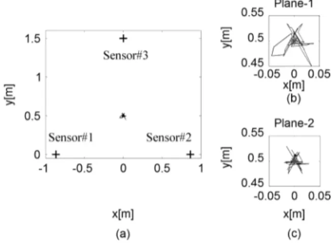
The two-dimension (2D) trilateration setup is shown in Fig. 16. The three sensors (original XETS antennas, [20]) are mounted at the vertices of an equilateral triangle with 1.73 m side, with vertical polarization. The hybrid antenna is attached to an azimuth positioner at the center of the triangle, exactly at 1 m distance from each sensor. The photo shows the cluttered surrounding environment, which remains static during the measurements. This set-up enables to isolate the hybrid antenna ranging performance, by eliminating the influence from the sensor antennas.
The three XETS sensors and the hybrid tag antenna are con-nected to a 4-port Vector Network Analyzer—VNA (Agilent Technologies E5071C 300 kHz—14 GHz ENA Series Network
Fig. 16. Localization setup with 3 sensors and 1 target.
Fig. 17. Position error as a function of angular rotation of the target for hybrid antenna for both planes 1 and 2.
Analyzer) and calibration is performed at the four antenna ports. Channel frequency response between each sensor and the hybrid antenna is measured in magnitude and phase over the frequency interval from 2 GHz to 12 GHz.
Distance information is calculated by post-processing, using the procedure detailed in [20]: measured channel frequency re-sponse is multiplied by the spectrum of an ultra-short Gaussian test pulse spanning the interval [3.1–10.6 GHz] and complying with FCC energy mask; when transformed into time-domain, this product provides a good estimation of the pulse ToA. A tri-lateration algorithm is then used to estimate the hybrid antenna position and the corresponding error with respect to its actual position.
Fig. 17 shows the estimated position error (distance between actual and estimated position from experimental data) when the hybrid antenna is rotated about its axis in plane-1 and -2, at 1 m constant distance to the target. Plane-1 corresponds to cross-polarization link, while plane-2 corresponds to co-cross-polarization link. The obtained average position error is in the order of 2 cm, with best results for the co-polarization measurement. It is worth noting that even for cross-polarization, the distance error does not exceed 6.5 cm.
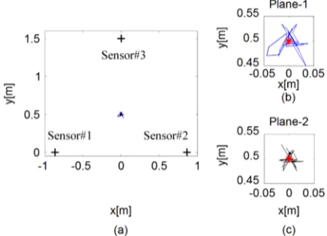
Fig. 18 shows a top view of the test plane, with the representa-tion of the estimated tag posirepresenta-tion for each angular orientarepresenta-tion of
IEEE Proof
Web Version
CRUZ et al.: HYBRID UHF/UWB ANTENNA FOR PASSIVE INDOOR IDENTIFICATION AND LOCALIZATION SYSTEMS 7
Fig. 18. (a) Real and measured target position using hybrid antenna for both planes, (b) zoomed measured target position for plane-1; (c) zoomed measured target position for plane-2.
the tag in plane-1 and -2. It demonstrates very good positioning performance obtained with the proposed hybrid antenna.
As mentioned before, the antenna is subsequently put through a second test, by integrating it with a commercial active system for UWB ranging: PulsON 400 model from the time domain manufacturer [15]. The objective is to evaluate the hybrid an-tenna performance compared to commercial solutions that work only for UWB, even if the above equipment comes configured for its own antennas. Furthermore, this allows testing the an-tenna for larger distances. In this test a pair of anan-tennas is placed face-to-face with co-polar alignment and distance in the interval from 1.5 m to 6.5 m, in the same indoor environment as be-fore. Two different antennas are tested: manufacturer-manufac-turer, and hybrid-hybrid (more than one copy of the hybrid an-tenna was fabricated for these tests to evaluate repeatability). The PulsON 400 system transmits a train of pulses with a spec-trum in the interval 3.1 GHz to 5.3 GHz, and the average from 100 distance readings is logged for each case, along with the standard deviation.
Results from measured distance error are summarized in Fig. 19. Measurements at 1.5 m are used for calibration of systematic errors and consequently Fig. 19 presents zero error for that distance. It is seen that distance errors for both antennas increase with distance but are less than 5% of the distance for Time Domain proprietary antennas, with standard deviations in the order of 4 cm; for the new hybrid tag antennas the distance error is slightly better % . The same line-of-sight tests were repeated in several areas of the lab with different lateral clutter, and similar results were obtained. It is therefore reason-able to assume that the developed antenna allows at least the same ranging performance from available commercial antennas that are currently used in this type of equipment for UWB localization, but with the added advantage of simultaneous correct operation in the UHF RFID band.
IV. CONCLUSION
A new hybrid antenna has been developed for passive object identification and localization in indoor environments. The antenna can be used in a system where the reader activates
Fig. 19. Distance error for different measurement distance with different com-binations of antennas using PulseON equipment.
the tag’s chip through a narrowband UHF signal and the tag answers with ultra-short UWB pulses, allowing its position determination with centimeter-class resolution. The antenna topology was specifically designed to allow UHF and UWB ports to be close enough to be compatible with a few mm chip. It is a compact, low-profile and potentially low-cost solution (possibly with the same price of current RFID passive tags with identification function only).
Despite the fact that these hybrid chips do not yet exist com-mercially, the finished hybrid antenna was experimentally tested using a commercial RFID chip to test RFID performance; also the ranging performance of the same antenna loaded with the RFID chip was tested using both synthesized pulses based on VNA channel measurement (for full FCC UWB characteriza-tion) as well as a commercial ranging system based on actual impulse radio. In all cases the hybrid antenna performed simi-larly to best available solutions that work either on RFID or on UWB, with the added advantage of performing well simultane-ously on both bands. It is relevant to mention that the study was complete for the whole solid angle of the antenna. Repeatability tests showed that the design is robust with respect to fabrication tolerance.
Thus, the hybrid antenna is appropriate for potential systems that combine identification and centimeter-class indoor local-ization using passive and therefore very low cost technology. This type of solution does not exist in current commercial sys-tems and encourages the emergence of new applications for the general public, which are expected to have explosive growth in the coming years.
ACKNOWLEDGMENT
The authors acknowledge the collaboration from C. Brito for prototype construction, and A. Almeida for prototype measure-ments.
REFERENCES
[1] Z. Sahinoglu, S. Gezici, and I. Guvenc, Ultra-Wideband Positioning
Systems. Cambridge, UK: Cambridge Univ. Press, 2008.
[2] K. Curran et al., “An evaluation of indoor location determination tech-nologies,” J. Location Based Serv., vol. 5, no. 2, pp. 61–78, June 2011. [3] R. Salomon, M. Schneider, and D. Wehden, “Low-cost optical indoor localization system for mobile objects without image processing,” in
Proc. IEEE Conf. on Emerging Technologies and Factory Automation (ETFA’06), Sep. 2006, pp. 629–632.
IEEE Proof
Web Version
[4] O. J. Woodman and R. K. Harle, “Concurrent scheduling in the activebat location system,” in Proc. 8th IEEE Int. Conf. on Pervasive
Com-puting and Communications Workshops (PERCOM Workshops), Apr.
2010, pp. 431–437.
[5] L. Hui et al., “Survey of wireless indoor positioning techniques and systems,” IEEE Trans. Syst., Man, Cybern., Part C: Applicat. Rev., vol. 37, pp. 1067–1080, Nov. 2007.
[6] F. Shih-Hau and L. Tsung-Nan, “A dynamic system approach for radio location fingerprinting in wireless local area networks,” IEEE Trans.
Commun., vol. 58, pp. 1020–1025, Apr. 2010.
[7] L. M. Ni, Z. Dian, and M. R. Souryal, “RFID-based localization and tracking technologies,” IEEE Wireless Commun., vol. 18, pp. 45–51, Apr. 2011.
[8] S. S. Saad and Z. S. Nakad, “A standalone RFID indoor positioning system using passive tags,” IEEE Trans. Ind. Electron., vol. 58, pp. 1961–1970, May 2011.
[9] C. R. Medeiros, J. R. Costa, and C. A. Fernandes, “RFID smart shelf with confined detection volume at UHF,” IEEE Antennas Wireless
Propag. Lett., vol. 7, pp. 773–776, 2008.
[10] C. R. Medeiros, J. R. Costa, and C. A. Fernandes, “RFID reader an-tennas for tag detection in self-confined volumes at UHF,” IEEE
An-tennas Propag. Mag., vol. 53, pp. 39–50, Apr. 2011.
[11] C. C. Serra, C. R. Medeiros, J. R. Costa, and C. A. Fernandes, “Mirror-integrated transparent antenna for RFID application,” IEEE Antennas
Wireless Propag. Lett., vol. 10, pp. 776–779, 2011.
[12] M. Lieshout, L. Grossi, G. Spinelli, S. Helmus, L. Kool, L. Pennings, R. Stap, T. Veugen, B. der Waaij, and C. Borean, “RFID Technologies: Emerging Issues, Challenges and Policy Options, Institute for Prospec-tive Technological Studies, European Commission, Tech. Report, EUR 22770 EN, 2007.
[13] Federal Communications Commission (FCC) First Order and Report: Revision of Part 15 of the Commission’s Rules Regarding UWB Trans-mission Systems FCC 02-48, Apr. 22, 2002.
[14] Commission Decision on allowing the use of the radio spectrum for equipment using ultra-wideband technology in a harmonised manner in the Community, Official J. Eur. Union, 2007/131/EC Feb. 23, 2007. [15] Time Domain Corporation. Huntsville, AL, Feb. 2012 [Online].
Available: www.timedomain.com
[16] Ubisense Limited, Feb. 2012 [Online]. Available: www.ubisense.net [17] Z. Zou, M. Baghaei-Nejad, H. Tenhunen, and L.-R. Zheng, “An
efficient passive RFID system for ubiquitous identification and sensing using impulse UWB radio,” in Elektrotechnik &
Information-stechnik. Berlin, Germany: Springer Wien, Nov. 2007, vol. 124, pp.
397–403, no. 11.
[18] M. B. Nejad, C. R. Chen, and L. R. Zheng, “An innovative semi-UWB passive transponder for wireless sensor and RFID applications,” pre-sented at the IEEE ICIIS Conf., 2006.
[19] S. Radiom et al., “Far-field on-chip antennas monolithically integrated in a wireless-powered 5.8 GHz downlink/UWB uplink RFID tag in 0.18 m standard CMOS,” IEEE J. Solid-State Circ., vol. 45, pp. 1746–1758, Sept. 2010.
[20] J. R. Costa, C. R. Medeiros, and C. A. Fernandes, “Performance of a crossed exponentially tapered slot antenna for UWB systems,” IEEE
Trans. Antennas Propag., vol. 57, no. 5, pp. 1345–1352, May 2009.
[21] C. R. Medeiros, J. R. Costa, and C. A. Fernandes, “Compact tapered slot Uwb antenna with Wlan band rejection,” IEEE Antennas Wireless
Propag. Lett., vol. 8, pp. 661–664, 2009.
[22] Alien Technology. Morgan Hill, CA, Feb. 2012 [Online]. Available: http://www.alientechnology.com
[23] CST—Computer Simulation Tech, Feb. 2012 [Online]. Available: http://www.cst.com
[24] C. Cho, H. Choo, and I. Park, “Broadband RFID tag antenna with quasi-isotropic radiation pattern,” Electron. Lett., vol. 41, pp. 1091–1092, Sep. 2005.
[25] G. Marrocco, “The art of UHF RFID antenna design: Impedance-matching and size-reduction techniques,” IEEE Antennas Propag.
Mag., vol. 50, pp. 66–79, Feb. 2008.
[26] D. Lamensdorf and L. Susman, “Baseband-pulse-antenna techniques,”
IEEE Antennas Propag. Mag., vol. 36, pp. 20–30, Feb. 1994.
Catarina C. Cruz was born in Lisbon, Portugal,
in 1986. She received the Licenciado and M.Sc. degrees in telecommunications engineering and computer science from the Instituto Universitário de Lisboa (ISCTE—IUL), Lisbon, Portugal, in 2009 and 2011, respectively. She is currently working toward the Ph.D. degree at the Instituto Superior Técnico (IST), Technical University of Lisbon, Lisbon, Portugal.
Since 2010, she has been a researcher at the Insti-tuto de Telecomunicações (IT), focusing her work on antennas for wireless communications. Her current research interests are in the area of antennas for RFID and lenses.
Jorge R. Costa (S’97–M’03–SM’09) was born in
Lisbon, Portugal, in 1974. He received the Licen-ciado and Ph.D. degrees in electrical and computer engineering from the Instituto Superior Técnico (IST), Technical University of Lisbon, Lisbon, Portugal, in 1997 and 2002, respectively.
He is currently a Researcher at the Instituto de Telecomunicações, Lisbon, Portugal. He is also an Assistant Professor at the Departamento de Ciências e Tecnologias da Informação, Instituto Universitário de Lisboa (ISCTE—IUL). His present research in-terests include lenses, reconfigurable antennas, MEMS switches, UWB, MIMO and RFID antennas. He is the coauthor of four patent applications and more than 50 contributions to peer reviewed journals and international conference proceedings. More than ten of these papers have appeared in IEEE Journals.
Prof. Costa is currently serving as an Associate Editor for the IEEE TRANSACTIONS ONANTENNAS ANDPROPAGATION.
Carlos A. Fernandes (S’86–M’89–SM’08)
re-ceived the Licenciado, M.Sc., and Ph.D. degrees in electrical and computer engineering from Instituto Superior Técnico (IST), Technical University of Lisbon, Lisbon, Portugal, in 1980, 1985, and 1990, respectively.
He joined IST in 1980, where he is presently Full Professor at the Department of Electrical and Computer Engineering in the areas of microwaves, radio wave propagation and antennas. He is a Senior Researcher at the Instituto de Telecomunicações and member of the Board of Directors. He has been the leader of antenna activities in National and European Projects as RACE 2067-MBS (Mobile Broadband System), ACTS AC230-SAMBA (System for Advanced Mobile Broadband Applications) and ESA/ESTEC-ILASH (Integrated Lens Antenna Shaping). He has coauthored a book, a book chapter, and more than 130 technical papers in peer reviewed international journals and conference proceedings, in the areas of antennas and radiowave propagation modeling. His current research interests include dielectric antennas for millimeter wave applications, antennas and propagation modeling for personal communication systems, RFID antennas, artificial dielectrics and metamaterials.
IEEE Proof
Print Version
IEEE TRANSACTIONS ON ANTENNAS AND PROPAGATION, VOL. 61, NO. 1, JANUARY 2013 1
Hybrid UHF/UWB Antenna for Passive Indoor
Identification and Localization Systems
Catarina C. Cruz, Jorge R. Costa, Senior Member, IEEE, and Carlos A. Fernandes, Senior Member, IEEE
Abstract—There is a growing interest for simultaneous
identifi-cation and centimetre-resolution localization of multiple targets in indoor environments. A hybrid passive UHF/UWB RFID concept has been recently proposed that conciliates the potential from high resolution UWB impulse radio with the typical range from UHF-RFID identification systems. This paper proposes a new planar an-tenna for hybrid passive tag systems, which operates both in the UHF-RFID band and in the FCC UWB band. The co-designed UHF and UWB antenna elements are printed back-to-back on each side of a common substrate with appropriate topology for future integration with a single UHF-UWB RFID chip. Experimental tests have shown that both UHF-RFID and UWB performance of the hybrid antenna are comparable to available commercial solutions that work just on a single band. The antenna is adequate for low-cost mass production of hybrid passive tags. It aims at low-low-cost pas-sive RFID systems combining the ability of item identification with precise tracking in indoor environments.
Index Terms—Indoor localization and identification, passive tag
antenna, dual-band antenna, RFID, UWB. I. INTRODUCTION
T
HERE is a high demand for reliable and accurate indoor real-time identification and tracking of persons and/or ob-jects, where satellite-based services fail. The growing market of Real-Time Location Systems (RTLS) is expected to reach 2700 million US dollars in 2016 [1] yet most of the available com-mercial solutions are still not 100% reliable [2] and have high associated costs.Usual indoor RTLS are based on optical, infrared, ultra-sounds, radio frequency or a combination of these technolo-gies. Optical and infrared systems are very accurate but require line of sight [3]. Ultrasounds are also highly accurate but they are susceptible to environment noise [4]. Hybrid systems combining optical imaging with infrared and ultrasound have been widely explored for example in gamepads for the general public. Although the accuracy of these systems is generally very good, the major limitation is the number of objects that can be simultaneously tracked, especially when they obstruct each Manuscript received February 11, 2012; revised July 15, 2012; accepted Au-gust 20, 2012. Date of publication September 21, 2012; date of current ver-sion December 28, 2012. This work was supported in part by Fundação para a Ciência e Tecnologia under Project RFIDLocal PTDC/EEA-TEL/102390/2008. C. C. Cruz, J. R. Costa and C. A. Fernandes are with Instituto de Telecomu-nicações, Instituto Superior Técnico, Technical University of Lisbon, 1049-001 Lisboa, Portugal (e-mail: [email protected]).
J. R. Costa is also with Instituto Universitário de Lisboa (ISCTE-IUL), Depar-tamento de Ciências e Tecnologias da Informação, 1649-026 Lisboa, Portugal. Color versions of one or more of the figures in this paper are available online at http://ieeexplore.ieee.org.
Digital Object Identifier 10.1109/TAP.2012.2220112
other. Even more critical is the fact that unique identification is not possible in general.
Radio frequency RTLS can overcome this limitation by pro-viding unique identification of the object and in some cases also the location, although generally with less accuracy than the pre-viously described systems. The most common radio frequency RTLS are based on RFID or UWB technologies [5].
Current commercial RFID systems are designed for item identification only, but they can still be used for coarse posi-tioning. In one common approach, coarse tag positioning is obtained by comparing its received signal strength (RSS) with the RSS from neighboring tags located in pre-defined positions [6]. Accuracies are in the order of 1 m, limited by RSS strong dependence on the environment and tag orientation [7], [8]. In a different perspective, RFID reader antennas can be designed to self-delimit a near-field detection zone, enabling selective identification of only those objects that are placed above a given shelf [9], on a conveyor belt [10] or in front of a mirror [11]. Despite the lower resolution from RFID based RTLS, this is one of the cheapest solutions per item, especially when using battery-less (or passive) tags. Passive tags do not require maintenance and its unit cost for the UHF band is expected to reach 0.05 US dollars between 2014 and 2016 [12].
In UWB localization systems, distance to the target is obtained from time-of-arrival (ToA) of sub-nanosecond trans-mitted pulses. These systems typically achieve centimeter resolution [1]. Regulations for UWB authorize unlicensed use of 3.1 to 10.6 GHz spectrum in US [13] and 6 to 8.5 GHz in Europe [14], subject to a spectral power density limit of dBm/MHz. This ensures spectrum sharing with other estab-lished narrowband applications without mutual interference, but at the same time it implies a severe range limitation. UWB systems are highly immune to multipath interference, have low power consumption and involve low complexity transceivers since baseband transmission is used. Commercial UWB lo-calization solutions already exist based upon active tags [15], [16]. However, passive UWB tag solutions would be more at-tractive for low-cost, maintenance-free large-scale deployment applications, if the range limitation could be overcome. In fact, regulation compliant ultra-wideband pulses are insufficient to energize passive tag’s chips, unlike what is done in UHF RFID. An alternative approach has been presented in [17] where a narrowband continuous wave UHF RFID signal is broadcast by the reader, which carries the clock, commands, and energy to power-up the chip on the tag, whereas it responds with UWB pulses. The feasibility of the UHF/UWB hybrid concept is demonstrated in [18] using a breadboard circuit with discrete components and well separated UWB and UHF antennas to 0018-926X/$31.00 © 2012 IEEE
IEEE Proof
Print Version
avoid mutual influence. This large circuit is not practical forreal applications. In [19] a UHF/UWB hybrid chip is developed with on-chip UHF and UWB antennas each one connected to the respective port. The solution is very compact with a few mm square, but the downside is the achievable range of only 7 cm because of insufficient on-chip antenna size. This motivates the development in the present work of a single external efficient antenna with two independent ports (for the UHF and UWB), located close enough to be compatible with a single chip similar to the one in [19] to boost the system range. The fundamental requirement for the antenna design is its simultaneous operation at UHF and in the FCC UWB band, with best possible pulse preservation for accurate estimation of ToA. The antenna is also required to be compact, lightweight and low-cost.
This paper is organized in four sections. The antenna design is described in Section II. The performance of a prototype is presented in Section III. Numerical and experimental RFID de-tection and ranging results are given and discussed throughout. Conclusions are finally drawn in Section IV.
II. ANTENNADESIGN
The schematic of the developed hybrid UHF-UWB antenna is presented in Fig. 1. It is a planar antenna comprising two metallic layers printed on each side of a
mm thick Duroid 5880 substrate with permittivity and loss tangent . One of the printed layers corre-sponds to the UHF radiating element and the other to the UWB element. The UHF element is based on a meandered line plus loop, while the UWB is a modified version of the Crossed Ex-ponential Tapered Slot antenna (XETS) proposed in [20], [21] which was shown to present excellent transient performance for the full UWB band. As will be explained ahead, one of the chal-lenges is to design and arrange the UHF and UWB elements in a way that minimizes mutual influence. Furthermore, the two elements are aligned so that the feeding ports almost overlap at each side of the substrate, see Fig. 1. In this way, a single hybrid RFID-UWB chip can be used to connect its ports directly and through vias to the antenna ports. Actually such hybrid IC chip is not yet available commercially, although a similar one has been demonstrated in [19] for on-chip antennas. Therefore, in order to design and test the antenna, it is assumed that the hybrid chip will present a differential port for UWB with 50 input impedance. For the UHF port, it is assumed that the chip will present the input impedance of current commercial UHF RFID ICs. The antenna is designed considering the input impedance
of the ALIEN Higgs-2 IC which is [22],
which is available at our lab for integration and test. Alternative chips can be easily accommodated in the design.
A. RFID Chip Characterization
Since the RFID chip on the UHF side of the substrate is di-rectly on top of the UWB terminals on the other face of the tenna, the chip is expected to influence as well the UWB an-tenna impedance and radiation performance. Thus, it is essen-tial to obtain a lumped model describing the chip behavior for both bands, to be used in the electromagnetic solver. The chip manufacturer provides a lumped model only for the UHF band,
Fig. 1. Exploded view of the hybrid RFID-UWB antenna showing the two met-alized faces from each side of a common planar substrate.
Fig. 2. Lumped component model of chip “Higgs-2 EPC Class 1 Gen 2”: (a) provided by the manufacturer for UHF RFID; (b) used to describe both UHF and full UWB band behavior.
Fig. 3. Microstrip test line with RFID chip at half-length: (a) fabricated proto-type; (b) simulation model in CST.
a parallel between a 1500 resistor and a 1.2 pF capacitor, see Fig. 2(a). This is not enough to model the chip for the full FCC UWB band.
A procedure that combines simulated and measured results is used to de-embed the RFID chip impedance up to 10.6 GHz. Two test circuits were manufactured: a reference circuit corre-sponding to a straight 50 microstrip line and a second circuit with a microstrip line with the same dimensions but with a gap at half length, loaded at that point with the chip under test, see Fig. 3. Both circuits are replicated in the CST Microwave Studio [23], where the RFID chip is modeled by a lumped circuit, Fig. 2(b). The lumped model parameters are adjusted to max-imize the correlation between measured and simulated curves of and versus frequency. Table I presents the final com-ponent values.
Fig. 4 compares magnitude and phase of measured and sim-ulated and curves, using either the manufacturer UHF model or the proposed extended model.
Fig. 4 confirms that the manufacturer model agrees with the measured curves for UHF ( GHz). However, only the new model agrees well for the extended band, namely for high mag-nitude values of from 2 to 6 GHz. The extended model is
IEEE Proof
Print Version
CRUZ et al.: HYBRID UHF/UWB ANTENNA FOR PASSIVE INDOOR IDENTIFICATION AND LOCALIZATION SYSTEMS 3
TABLE I
COMPONENTVALUES FOR THELUMPEDELEMENTMODELS OF THECHIP
Fig. 4. Magnitude ((a) and (b)) and phase ((c) and (d)) for s11 and s21, respec-tively, measured ( ) and simulated ( ) using the proposed extended model for both UHF and UWB bands and using the manufacturer model (ALIEN) ( ).
used throughout in CST for the co-design of the UHF and UWB radiating elements.
B. Design of the RFID Part of the Antenna
Design and performance of the RFID part of the hybrid an-tenna are affected by the presence of the XETS on the other face of the substrate, and vice-versa. By choosing an appropriate ori-entation and alignment of the two radiating elements at each side of the substrate, to be detailed ahead, it is possible to minimize its mutual influence. At a first step of the UHF element opti-mization, a previous XETS design is used on the other face of the substrate, loaded with 50 at its port.
The geometry of the UHF-RFID element in Fig. 5 shows a double loop connected to a meandered dipole. Since UHF and UWB ports must be close in the xy-plane as explained, two mi-crostrip lines are used inside the loop to connect the UHF RFID chip at the center. The lines are very narrow (0.4 mm) and posi-tioned in a way that minimizes the interference with the XETS antenna on the opposite side.
The antenna RFID port impedance must equal the complex conjugate of the chip impedance, for maximum power transfer: at 860 MHz. Thus, the antenna impedance must exhibit inductive behavior, which is achieved using the loop. The adopted double-loop configuration en-hances bandwidth compared to a single loop [24]. The loop itself presents insignificant real part of the impedance, so the radiating behavior is obtained with the addition of a dipole, which is meandered to reduce its length.
The described UHF-RFID element is optimized to operate for the three geographic worldwide region sub-bands: 865–868 MHz for Europe, 902–928 MHz for U.S. and 952–954 MHz for Japan. The obtained parameter values are given in Table II.
Fig. 5. Geometry of the RFID face of the hybrid antenna, designed with CST Microwave Studio.
TABLE II
PARAMETERVALUES OF THERFID FACE INMILLIMETERS
Fig. 6. Simulated Power Transmission Coefficient for the proposed hybrid an-tenna and for ALIENS’s Squiggle tag.
It makes sense to analyze the power transfer coefficient from the antenna to the chip, as this relates directly to the tag achievable range. It measures the maximum fraction of the available power at the antenna port that is transferred to the chip [25]. The simulated result is presented in Fig. 6 (dotted green curve). Power transmission is above 70% level across the entire UHF band (from 860 MHz to 960 MHz). Superimposed on Fig. 6 is the transmission coefficient for the commercial tag ALN-9640 Squiggle Alien [22] that uses the same RFID chip (solid blue curve). It is noted that the hybrid tag presents com-parable performance within the UHF-RFID band, though with marginally lower power transfer values. This will be improved at a later stage of the hybrid antenna design, as detailed ahead.
Fig. 7 shows the simulated radiation pattern at 866 MHz. The hybrid antenna presents at UHF-RFID a typical dipole-like ra-diation pattern. Similar behavior is observed across the whole UHF-RFID band.
C. Design of the UWB Part of the Antenna
The XETS element used on the UWB face of the antenna (Fig. 8) derives from the original version demonstrated by the authors in [20], [21] for the full FCC UWB band (3.1 GHz to
IEEE Proof
Print Version
Fig. 7. Simulated UHF-RFID far-field radiation pattern at 866 MHz.
Fig. 8. Parameters defining the UWB face of the hybrid antenna [20]: (a) single exponentially tapered slot; (b) star slot.
Fig. 9. Representative scheme of the orientation of the two overlapping faces of the hybrid antenna considering a transparent substrate.
10.6 GHz). This antenna has stable radiation pattern, well de-fined linear polarization and very well dede-fined constant phase center versus frequency.
Some modifications of the original XETS configuration are however necessary for integration into the hybrid antenna. It is reduced to a single metallization layer and the feeding is done directly at the XETS front face. As in [20], [21], a thin semi-rigid coaxial cable EZ-41 (1.19 mm diameter), is used for that (Fig. 9).
As in the previous Section, the optimization of the UWB an-tenna shape parameters is performed with the UHF anan-tenna on the other side, loaded by the RFID chip model from Section II.A. Table III summarizes the obtained XETS parameter values pre-sented in Fig. 8 and keeping the same nomenclature from [20].
Fig. 10. Hybrid antenna prototype: (a) UWB face; (b) RFID face.
Fig. 11. Setup for measuring RFID range inside the anechoic chamber.
The slot exponential geometry is given by the width at the slot longitudinal coordinate measured from the centre of the slot, see Fig. 8. Slot width at the centre is is the exponen-tial expansion parameter and is the antenna thickness. Simu-lated VSWR curve and radiation pattern are shown in Figs. 13, 14 and 15 with experimental results.
This change in the XETS shape influences the previously designed UHF-RFID element performance. Fig. 6 shows the corresponding power transfer coefficient after replacing the XETS by the modified one (dashed red curve): actually the power transfer characteristic improves, becoming much similar to Squiggle’s. Thus, no further iteration of the design process is required.
III. ANTENNAEXPERIMENTALPERFORMANCE Fig. 10 shows both faces of the manufactured prototype. The coaxial cable is connected between two opposed petals from the UWB antenna (Fig. 10(a)) and the RFID chip is soldered at the UHF port (Fig. 10(b)). Corresponding experimental RFID detection and UWB ranging performance is analyzed next.
A. RFID Performance
The RFID reading range of the hybrid antenna is evaluated in-side an anechoic chamber. For this purpose, the antenna under test is attached to an azimuth positioner, with due care to avoid unwanted reflections from antenna back lobe. The RFID reader antenna is attached to a tripod and pointed to the center of the hybrid antenna. For each azimuth orientation of the hybrid an-tenna (at 15 steps of the azimuth positioner), the tripod travels
IEEE Proof
Print Version
CRUZ et al.: HYBRID UHF/UWB ANTENNA FOR PASSIVE INDOOR IDENTIFICATION AND LOCALIZATION SYSTEMS 5
Fig. 12. Polar RFID detection range charts for the hybrid antenna at the planes: (a) E1 (xz plane); (b) E2 (xy plane); (c) H (yz plane).
Fig. 13. Measured and simulated VSWR curve of UWB port of the hybrid antenna with a RFID chip placed in the RFID port.
along the link direct path to determine the corresponding edge of the RFID detection region.
Commercial circular polarized antenna ALR-8610-AC and ALR-8800 Enterprise Scalable RFID Reader from ALIEN are used in these tests. Its power is adjusted to limit detection to the maximum measurable distance inside the anechoic chamber (4 m). Results for the antenna main planes are presented in Fig. 12. The z-axis (plane-E1) and y-axis (plane-E2) correspond to face-to-face alignment of tag and reader antenna (Fig. 11). The results are consistent with the radiation pattern from Fig. 7, resembling a dipole radiation pattern with nulls along the x-axis (dipole axis).
The same test is repeated for the commercial ALIEN ALN-9640 Squiggle passive tag [22] that uses the same RFID chip.
Fig. 14. Measured ( ) and ( ) and simulated ( ) and ( ) radiation patterns at GHz: (a) plane-1 magnitude; (b) plane-2 mag-nitude; (c) plane-1 phase; (d) plane-2 phase.
Obtained results are practically coincident with the hybrid an-tenna results, also with a maximum range of about 4 m. If max-imum allowed reader power is used in open space, both tags are detected up to 8 m distance. Tests show that the RFID perfor-mance of the proposed hybrid antenna tag is comparable to the performance of a standard commercial passive tag. However, as will be demonstrated next, the developed antenna further op-erates simultaneously in the FCC UWB band, which is not the case of available commercial RFID tags.
B. UWB Performance
Measured VSWR of the hybrid antenna is superimposed on simulations in Fig. 13. There is a good match between measured and simulated curves across the FCC UWB band, with values mostly below 2. Although VSWR of the UWB antenna degrades near the edges of the UWB band, this does not compromise localization performance for impulse-based systems. The used pulse is identical to the one presented in [20], (5). It is defined by
(1) where the central frequency is GHz in order to center the pulse spectrum within the UWB band and the Gaussian width is ps to comply with the FCC indoor spec-trum mask. In fact the pulse specspec-trum decreases significantly near the edges of the UWB band. Therefore, the pulse shape is not affected by the slight restriction of the operation band at the edges. Pulse fidelity, [26] which quantifies the pulse preserva-tion performance of the antenna is 95% in the main direcpreserva-tion.
Measured radiation patterns are shown in Figs. 14 and 15 at 5 GHz and 7.5 GHz, respectively, superimposed on the CST simu-lated curves. The same figures present the absolute gain: it is 3.4 dBi at 5 GHz and 6.1 dBi at 7.5 GHz. These values are similar to those previously obtained for the stand-alone UWB antenna described in [20] which was characterized between 3.1 and 10.6 GHz. Unlike the original XETS [20], [21], the presence of UHF part of the hybrid antenna precludes a stable and well-defined polarization in the UWB band. However, this does not prevent
IEEE Proof
Print Version
Fig. 15. Measured ( ) and ( ) and simulated ( ) and ( ) radiation patterns at .5 GHz: (a) plane-1 magnitude; (b) plane-2 magnitude; (c) plane-1 phase; (d) plane-2 phase.
TABLE III
PARAMETERVALUES OF THEXETS ANTENNA INmm
good positioning accuracy as will be discussed ahead. Measured phase pattern is almost horizontal within the main lobe, as seen in (c) and (d) plots from Figs. 14 and 15. It indicates that the an-tenna phase center position is constant, near its geometric center in both planes and both frequencies, a fundamental character-istic to preserve the pulse shape.
C. Localization Performance
The final goal of the design of this antenna is its integration with an identification and localization system. Therefore indoor localization trials are performed to determine the antenna per-formance. Two different experimental tests are carried out: in the first test, the position of the hybrid tag in a plane is de-termined using synthesized pulses in the frequency domain to-gether with a trilateration algorithm based on pulse time-of-ar-rival (ToA); in the second test, the developed antenna is used directly on a commercial active UWB ranging system that trans-mits actual time domain pulses.
The two-dimension (2D) trilateration setup is shown in Fig. 16. The three sensors (original XETS antennas, [20]) are mounted at the vertices of an equilateral triangle with 1.73 m side, with vertical polarization. The hybrid antenna is attached to an azimuth positioner at the center of the triangle, exactly at 1 m distance from each sensor. The photo shows the cluttered surrounding environment, which remains static during the measurements. This set-up enables to isolate the hybrid antenna ranging performance, by eliminating the influence from the sensor antennas.
The three XETS sensors and the hybrid tag antenna are con-nected to a 4-port Vector Network Analyzer—VNA (Agilent Technologies E5071C 300 kHz—14 GHz ENA Series Network
Fig. 16. Localization setup with 3 sensors and 1 target.
Fig. 17. Position error as a function of angular rotation of the target for hybrid antenna for both planes 1 and 2.
Analyzer) and calibration is performed at the four antenna ports. Channel frequency response between each sensor and the hybrid antenna is measured in magnitude and phase over the frequency interval from 2 GHz to 12 GHz.
Distance information is calculated by post-processing, using the procedure detailed in [20]: measured channel frequency re-sponse is multiplied by the spectrum of an ultra-short Gaussian test pulse spanning the interval [3.1–10.6 GHz] and complying with FCC energy mask; when transformed into time-domain, this product provides a good estimation of the pulse ToA. A tri-lateration algorithm is then used to estimate the hybrid antenna position and the corresponding error with respect to its actual position.
Fig. 17 shows the estimated position error (distance between actual and estimated position from experimental data) when the hybrid antenna is rotated about its axis in plane-1 and -2, at 1 m constant distance to the target. Plane-1 corresponds to cross-polarization link, while plane-2 corresponds to co-cross-polarization link. The obtained average position error is in the order of 2 cm, with best results for the co-polarization measurement. It is worth noting that even for cross-polarization, the distance error does not exceed 6.5 cm.
Fig. 18 shows a top view of the test plane, with the representa-tion of the estimated tag posirepresenta-tion for each angular orientarepresenta-tion of
IEEE Proof
Print Version
CRUZ et al.: HYBRID UHF/UWB ANTENNA FOR PASSIVE INDOOR IDENTIFICATION AND LOCALIZATION SYSTEMS 7
Fig. 18. (a) Real and measured target position using hybrid antenna for both planes, (b) zoomed measured target position for plane-1; (c) zoomed measured target position for plane-2.
the tag in plane-1 and -2. It demonstrates very good positioning performance obtained with the proposed hybrid antenna.
As mentioned before, the antenna is subsequently put through a second test, by integrating it with a commercial active system for UWB ranging: PulsON 400 model from the time domain manufacturer [15]. The objective is to evaluate the hybrid an-tenna performance compared to commercial solutions that work only for UWB, even if the above equipment comes configured for its own antennas. Furthermore, this allows testing the an-tenna for larger distances. In this test a pair of anan-tennas is placed face-to-face with co-polar alignment and distance in the interval from 1.5 m to 6.5 m, in the same indoor environment as be-fore. Two different antennas are tested: manufacturer-manufac-turer, and hybrid-hybrid (more than one copy of the hybrid an-tenna was fabricated for these tests to evaluate repeatability). The PulsON 400 system transmits a train of pulses with a spec-trum in the interval 3.1 GHz to 5.3 GHz, and the average from 100 distance readings is logged for each case, along with the standard deviation.
Results from measured distance error are summarized in Fig. 19. Measurements at 1.5 m are used for calibration of systematic errors and consequently Fig. 19 presents zero error for that distance. It is seen that distance errors for both antennas increase with distance but are less than 5% of the distance for Time Domain proprietary antennas, with standard deviations in the order of 4 cm; for the new hybrid tag antennas the distance error is slightly better % . The same line-of-sight tests were repeated in several areas of the lab with different lateral clutter, and similar results were obtained. It is therefore reason-able to assume that the developed antenna allows at least the same ranging performance from available commercial antennas that are currently used in this type of equipment for UWB localization, but with the added advantage of simultaneous correct operation in the UHF RFID band.
IV. CONCLUSION
A new hybrid antenna has been developed for passive object identification and localization in indoor environments. The antenna can be used in a system where the reader activates
Fig. 19. Distance error for different measurement distance with different com-binations of antennas using PulseON equipment.
the tag’s chip through a narrowband UHF signal and the tag answers with ultra-short UWB pulses, allowing its position determination with centimeter-class resolution. The antenna topology was specifically designed to allow UHF and UWB ports to be close enough to be compatible with a few mm chip. It is a compact, low-profile and potentially low-cost solution (possibly with the same price of current RFID passive tags with identification function only).
Despite the fact that these hybrid chips do not yet exist com-mercially, the finished hybrid antenna was experimentally tested using a commercial RFID chip to test RFID performance; also the ranging performance of the same antenna loaded with the RFID chip was tested using both synthesized pulses based on VNA channel measurement (for full FCC UWB characteriza-tion) as well as a commercial ranging system based on actual impulse radio. In all cases the hybrid antenna performed simi-larly to best available solutions that work either on RFID or on UWB, with the added advantage of performing well simultane-ously on both bands. It is relevant to mention that the study was complete for the whole solid angle of the antenna. Repeatability tests showed that the design is robust with respect to fabrication tolerance.
Thus, the hybrid antenna is appropriate for potential systems that combine identification and centimeter-class indoor local-ization using passive and therefore very low cost technology. This type of solution does not exist in current commercial sys-tems and encourages the emergence of new applications for the general public, which are expected to have explosive growth in the coming years.
ACKNOWLEDGMENT
The authors acknowledge the collaboration from C. Brito for prototype construction, and A. Almeida for prototype measure-ments.
REFERENCES
[1] Z. Sahinoglu, S. Gezici, and I. Guvenc, Ultra-Wideband Positioning
Systems. Cambridge, UK: Cambridge Univ. Press, 2008.
[2] K. Curran et al., “An evaluation of indoor location determination tech-nologies,” J. Location Based Serv., vol. 5, no. 2, pp. 61–78, June 2011. [3] R. Salomon, M. Schneider, and D. Wehden, “Low-cost optical indoor localization system for mobile objects without image processing,” in
Proc. IEEE Conf. on Emerging Technologies and Factory Automation (ETFA’06), Sep. 2006, pp. 629–632.
IEEE Proof
Print Version
[4] O. J. Woodman and R. K. Harle, “Concurrent scheduling in the active bat location system,” in Proc. 8th IEEE Int. Conf. on Pervasive
Com-puting and Communications Workshops (PERCOM Workshops), Apr.
2010, pp. 431–437.
[5] L. Hui et al., “Survey of wireless indoor positioning techniques and systems,” IEEE Trans. Syst., Man, Cybern., Part C: Applicat. Rev., vol. 37, pp. 1067–1080, Nov. 2007.
[6] F. Shih-Hau and L. Tsung-Nan, “A dynamic system approach for radio location fingerprinting in wireless local area networks,” IEEE Trans.
Commun., vol. 58, pp. 1020–1025, Apr. 2010.
[7] L. M. Ni, Z. Dian, and M. R. Souryal, “RFID-based localization and tracking technologies,” IEEE Wireless Commun., vol. 18, pp. 45–51, Apr. 2011.
[8] S. S. Saad and Z. S. Nakad, “A standalone RFID indoor positioning system using passive tags,” IEEE Trans. Ind. Electron., vol. 58, pp. 1961–1970, May 2011.
[9] C. R. Medeiros, J. R. Costa, and C. A. Fernandes, “RFID smart shelf with confined detection volume at UHF,” IEEE Antennas Wireless
Propag. Lett., vol. 7, pp. 773–776, 2008.
[10] C. R. Medeiros, J. R. Costa, and C. A. Fernandes, “RFID reader an-tennas for tag detection in self-confined volumes at UHF,” IEEE
An-tennas Propag. Mag., vol. 53, pp. 39–50, Apr. 2011.
[11] C. C. Serra, C. R. Medeiros, J. R. Costa, and C. A. Fernandes, “Mirror-integrated transparent antenna for RFID application,” IEEE Antennas
Wireless Propag. Lett., vol. 10, pp. 776–779, 2011.
[12] M. Lieshout, L. Grossi, G. Spinelli, S. Helmus, L. Kool, L. Pennings, R. Stap, T. Veugen, B. der Waaij, and C. Borean, “RFID Technologies: Emerging Issues, Challenges and Policy Options, Institute for Prospec-tive Technological Studies, European Commission, Tech. Report, EUR 22770 EN, 2007.
[13] Federal Communications Commission (FCC) First Order and Report: Revision of Part 15 of the Commission’s Rules Regarding UWB Trans-mission Systems FCC 02-48, Apr. 22, 2002.
[14] Commission Decision on allowing the use of the radio spectrum for equipment using ultra-wideband technology in a harmonised manner in the Community, Official J. Eur. Union, 2007/131/EC Feb. 23, 2007. [15] Time Domain Corporation. Huntsville, AL, Feb. 2012 [Online].
Available: www.timedomain.com
[16] Ubisense Limited, Feb. 2012 [Online]. Available: www.ubisense.net [17] Z. Zou, M. Baghaei-Nejad, H. Tenhunen, and L.-R. Zheng, “An
efficient passive RFID system for ubiquitous identification and sensing using impulse UWB radio,” in Elektrotechnik &
Information-stechnik. Berlin, Germany: Springer Wien, Nov. 2007, vol. 124, pp.
397–403, no. 11.
[18] M. B. Nejad, C. R. Chen, and L. R. Zheng, “An innovative semi-UWB passive transponder for wireless sensor and RFID applications,” pre-sented at the IEEE ICIIS Conf., 2006.
[19] S. Radiom et al., “Far-field on-chip antennas monolithically integrated in a wireless-powered 5.8 GHz downlink/UWB uplink RFID tag in 0.18 m standard CMOS,” IEEE J. Solid-State Circ., vol. 45, pp. 1746–1758, Sept. 2010.
[20] J. R. Costa, C. R. Medeiros, and C. A. Fernandes, “Performance of a crossed exponentially tapered slot antenna for UWB systems,” IEEE
Trans. Antennas Propag., vol. 57, no. 5, pp. 1345–1352, May 2009.
[21] C. R. Medeiros, J. R. Costa, and C. A. Fernandes, “Compact tapered slot Uwb antenna with Wlan band rejection,” IEEE Antennas Wireless
Propag. Lett., vol. 8, pp. 661–664, 2009.
[22] Alien Technology. Morgan Hill, CA, Feb. 2012 [Online]. Available: http://www.alientechnology.com
[23] CST—Computer Simulation Tech, Feb. 2012 [Online]. Available: http://www.cst.com
[24] C. Cho, H. Choo, and I. Park, “Broadband RFID tag antenna with quasi-isotropic radiation pattern,” Electron. Lett., vol. 41, pp. 1091–1092, Sep. 2005.
[25] G. Marrocco, “The art of UHF RFID antenna design: Impedance-matching and size-reduction techniques,” IEEE Antennas Propag.
Mag., vol. 50, pp. 66–79, Feb. 2008.
[26] D. Lamensdorf and L. Susman, “Baseband-pulse-antenna techniques,”
IEEE Antennas Propag. Mag., vol. 36, pp. 20–30, Feb. 1994.
Catarina C. Cruz was born in Lisbon, Portugal,
in 1986. She received the Licenciado and M.Sc. degrees in telecommunications engineering and computer science from the Instituto Universitário de Lisboa (ISCTE—IUL), Lisbon, Portugal, in 2009 and 2011, respectively. She is currently working toward the Ph.D. degree at the Instituto Superior Técnico (IST), Technical University of Lisbon, Lisbon, Portugal.
Since 2010, she has been a researcher at the Insti-tuto de Telecomunicações (IT), focusing her work on antennas for wireless communications. Her current research interests are in the area of antennas for RFID and lenses.
Jorge R. Costa (S’97–M’03–SM’09) was born in
Lisbon, Portugal, in 1974. He received the Licen-ciado and Ph.D. degrees in electrical and computer engineering from the Instituto Superior Técnico (IST), Technical University of Lisbon, Lisbon, Portugal, in 1997 and 2002, respectively.
He is currently a Researcher at the Instituto de Telecomunicações, Lisbon, Portugal. He is also an Assistant Professor at the Departamento de Ciências e Tecnologias da Informação, Instituto Universitário de Lisboa (ISCTE—IUL). His present research in-terests include lenses, reconfigurable antennas, MEMS switches, UWB, MIMO and RFID antennas. He is the coauthor of four patent applications and more than 50 contributions to peer reviewed journals and international conference proceedings. More than ten of these papers have appeared in IEEE Journals.
Prof. Costa is currently serving as an Associate Editor for the IEEE TRANSACTIONS ONANTENNAS ANDPROPAGATION.
Carlos A. Fernandes (S’86–M’89–SM’08)
re-ceived the Licenciado, M.Sc., and Ph.D. degrees in electrical and computer engineering from Instituto Superior Técnico (IST), Technical University of Lisbon, Lisbon, Portugal, in 1980, 1985, and 1990, respectively.
He joined IST in 1980, where he is presently Full Professor at the Department of Electrical and Computer Engineering in the areas of microwaves, radio wave propagation and antennas. He is a Senior Researcher at the Instituto de Telecomunicações and member of the Board of Directors. He has been the leader of antenna activities in National and European Projects as RACE 2067-MBS (Mobile Broadband System), ACTS AC230-SAMBA (System for Advanced Mobile Broadband Applications) and ESA/ESTEC-ILASH (Integrated Lens Antenna Shaping). He has coauthored a book, a book chapter, and more than 130 technical papers in peer reviewed international journals and conference proceedings, in the areas of antennas and radiowave propagation modeling. His current research interests include dielectric antennas for millimeter wave applications, antennas and propagation modeling for personal communication systems, RFID antennas, artificial dielectrics and metamaterials.