Inês Margarida Neves Marcelino
Bachelor of Science in Materials Engineering
Additive Fabrication of Anepectic Meshes controlled by
a NiTi alloy
Dissertation to obtain the master’s degree in
Materials Engineering
Supervisor: Professor Doutor Francisco Manuel Braz Fernandes
Co-supervisor: Professor Doutor Alexandre José da Costa Velhinho
Jury
Chairperson: Professor Doutor Rui Jorge Cordeiro Silva
Rapporteurs: Professor Doutor João Paulo Miranda Ribeiro Borges Members: Professor Doutor Francisco Manuel Braz Fernandes
ii
Additive Fabrication of Anepectic Meshes controlled by a NiTi alloy
Copyright © Inês Margarida Neves Marcelino, Faculdade de Ciências e Tecnologia, Universidade Nova de Lisboa.
A Faculdade de Ciências e Tecnologia e a Universidade Nova de Lisboa têm o direito, perpétuo e sem limites geográficos, de arquivar e publicar esta dissertação através de exemplares impressos reproduzidos em papel ou de forma digital, ou por qualquer outro meio conhecido ou que venha a ser inventado, e de a divulgar através de repositórios científicos e de admitir a sua cópia e distribuição com objetivos educacionais ou de investigação, não comerciais, desde que seja dado crédito ao autor e editor.
iv
“You never know what you can do till you try.”
vi
ACNOWLEDGEMENTS
Em primeiro lugar gostava de agradecer aos meus orientadores, por me terem apoiado neste desafio. Professor Doutor Francisco Braz Fernandes e Professor Doutor Alexandre Velhinho, muito obrigada pela vossa dedicação, paciência e por todos os valores que me passaram.
Obrigada a toda a equipa do DCM e do CENIMAT que possibilitou a concretização desta dissertação, em especial agradeço ao Edgar Camacho e à Andreia Lopes. Obrigado aos professores que durante estes cinco anos, me mostraram o grandioso curso que é Engenharia de Materiais e todo o encanto desta ciência. Um grande obrigado à Joana Raminhos, não só por toda a ajuda, mas também por todo o companheirismo e amizade.
Todos os grandes percursos raramente se fazem sozinhos, durante estes cinco anos tive a oportunidade de conhecer pessoas muito boas e genuínas. Muito obrigada aos que estiveram lá para mim quando nem sempre foi fácil, João Duarte, Celina Palma, Rita Lobato e Tomás Fernandes, vocês tornaram este percurso muito melhor, obrigada por me aturarem.
Um obrigado muito sentido aos meus pais, ao meu irmão e à minha avó. Pais, obrigada por me terem dado esta oportunidade, obrigada por aguentarem as vezes que a faculdade roubava a atenção que devia ter sido dada a vocês, obrigada por me apoiarem nos meus momentos mais difíceis e estarem ao meu lado, e obrigada por toda a vossa dedicação e preocupação.
Por último, um enorme obrigada ao Filipe. Obrigada por toda a paciência, todo o amor e carinho. Obrigada por termos partilhado juntos esta etapa das nossas vidas, por teres sido o meu maior porto de abrigo e por temos estado lá um para outro. Um grande obrigada por me motivares a ser uma pessoa melhor.
viii
ABSTRACT
An anepectic material is a metamaterial which simultaneously exhibits a negative coefficient of thermal expansion (CTE) and a negative Poisson coefficient. These meshes may be applied in situations where a response to a thermal stimulus is desired, such as in the aerospace and medical fields. In the current work, anepectic composite meshes, made from ABS and NiTi alloys, were fabricated with the aid of an additive manufacturing technique and subsequently characterized. Seven different mesh designs or material combinations were tested. In every case, a common passive part consists of ABS. A complementary active part, consisting of NiTi wire, differed from case to case, whether in terms of the particular behavior demonstrated (shape memory effect [SME] an/or superelasticity [SE]), the temperature of the relevant phase transformation, the geometry adopted, or the diameter used. All meshes were tested in a silicone bath, and their CTE was measured. The results showed that, under careful parameter selection it is possible to achieve an anepectic effect by combining ABS with SME or SE wires. The mesh that showed to have a more negative CTE (-3008 x 10-6 ºC-1) combined SME wires with SE wires. With such combination, it was possible to activate the mesh bellow the glass transition of the polymer, at 38ºC. For one of the seven fabricated meshes, cyclic tests of three heating and cooling were performed. But only during the first cycle could the anepectic behavior be preserved, the CTE becoming positive on the remaining cycles. Finite element simulation was also performed, where both positive and negative mesh displacements were verified.
Keywords: 3D printing, Anepectic, Auxetic, Negative Thermal Expansion, NiTi alloys,
Shape Memory Alloys, Superelasticity
ix
RESUMO
Uma malha Anepéctica é um metamaterial que exibe simultaneamente um coeficiente de expansão térmico (CET) negativo e um coeficiente de Poisson negativo. Estas malhas podem ser aplicadas em situações onde é desejável uma resposta a um estímulo térmico, como por exemplo nas áreas da aeroespacial e da medicina. No trabalho presente, malhas compósitas Anepécticas, feitas de ABS e de ligas de NiTi, são fabricadas através de técnicas de fabricação aditiva e são consequentemente caracterizadas. Sete diferentes combinações de design, ou de material foram testadas. Em cada caso, a parte passiva consistia em ABS. A parte ativa complementar, consistia em arames de NiTi, diferindo de caso para caso, quer em termos do comportamento particular demonstrado (efeito de memória de forma [EMF] e/ou superelasticidade [SE]), a temperatura relevante da transformação de fase, a geometria adotada, ou o diâmetro usado. Todas as malhas foram testadas num banho de silicone e o seu CET foi medido. Os resultados demonstraram que, através de uma seleção cautelosa dos parâmetros é possível de atingir um efeito Anepético através da combinação de ABS com arames de EMF ou de SE. A malha que demonstrou ter um CET mais negativo (-3008 x 10-6 ºC-1) combina arames de EMF com SE. Com essas combinações, foi
possível atingir ativações abaixo da temperatura de transição vítrea do polímero, a 38ºC. Para uma das sete malhas fabricadas, foram efetuados três ciclos térmicos de aquecimentos e arrefecimentos. Porém, só durante o primeiro ciclo o efeito Anepéctico foi preservado, com o CET a tornar-se positivo nos restantes ciclos. Análise de elementos finitos foi também efetuada, onde se verificaram deslocamentos positivos e negativos.
Palavras-Chave: Impressão 3D, Anepéctica, Auxética, Expansão Térmica Negativa,
Ligas NiTi, Ligas de Memória de Forma, Superelasticidade
x
LIST OF CONTENT
Acnowledgements ... vi
Abstract ... viii
Resumo ... ix
List of Figures ... xii
List of Tables ... xiv
Acronyms ... xvi
Symbols ... xviii
Motivation and Objectives ... xx
1 Introduction ... 1
1.1. Auxetic and NTE materials ... 1
1.2. NiTi alloy – Shape Memory Effect and Superelasticity ... 4
1.3. Anepectic meshes controlled by NiTi alloy ... 4
2 Materials and Methods ... 6
2.1. Materials ... 6
2.1.1. Polymeric materials ... 6
2.1.2. Shape Memory Alloys ... 6
2.2. Mesh Design and Printing ... 8
2.3. Mesh characterization – CTE evaluation ... 9
3 Results and Discussion ... 10
3.1. Characterization of NiTi Wires ... 10
3.1.1. Thermal Analysis - Phase Transitions Temperatures ... 10
3.1.2. Tensile Tests ... 11
3.1.3. Thermo-mechanical Analysis ... 11
3.1.4. Forces Involved In each wire ... 13
3.2. ABS / NiTi Combination – Incorporation and Sizing ... 14
xi
3.4. Mono-Material ABS and without an active part meshes. ... 15
3.5. Testing of ABS/NiTi composite meshes ... 17
3.5.1. Effect of wire diameter ... 18
3.5.2. Effect of wires configuration ... 18
3.5.3. Separate effects of superelasticity and shape memory of active elements ... 19
3.5.4. Combined effects of superelastic and shape memory of active elements ... 20
3.5.5. Effect of sleeve geometry ... 21
3.5.6. Effect of heating and cooling cycles ... 22
3.5.7. Activation temperature and plastic flow during heating ... 23
3.6. Finite Model Analysis ... 24
4 Conclusions and Future perspectives ... 25
References ... 28
xii
LIST OF FIGURES
Figure 1.1 – The five main models of auxetic structures [8]-[12]……...………..1 Figure 1.2 - Metamaterials on Ai and Gao work [31][32]……..……….………...3 Figure 1.3 – Unit cell [2]. The red structs correspond to the active part and the blue beams to the
passive part of the mesh, this mesh has a re-entrant angle of 25º and a beam thickness of 1mm………....3
Figure 1.4 – Schematic of a NiTi DSC………...4 Figure 2.1 – DSC of NiTi alloys, in Figure 2.1.A it is represented the SME alloys (SME1 and
SME2), and in Figure B it is represented the SE alloys (SE1 and SE2). To be noted, the vertical line represents room temperature………..……….7
Figure 2.2 – Representative scheme of the three-point bending setup………8 Figure 2.3 – Interfacial adhesion test piece, the NiTi wire is represented in grey and the yellow
simulates the ABS passive part of the mesh, on the left image the red circle indicates the hole where the wire is inserted………...8
Figure 2.4 – Schematic of the test piece placed on the tensile machine. The Figure was taken after
the test was finished Schematic of the test piece (with the wire) placed on the tensile machine. On (a) is represented the assembly of the test piece on the tensile machine, this assembly allows a wire length to be secured outside the polymer matrix at the beginning of the pull-out test. On (b) is represented a photo taken after the test was finished…....……….………...8
Figure 2.5 – A unit cell with sleeves, and the sleeve in more detail. The a and b on the left Figure
are length parameters……….9
Figure 2.6 – Schematic of the CTE mesh testing setup [2]………9 Figure 3.1 – Tensile tests of NiTi wires: A- SE1; B- SE2; C- SME1; D- SME2………...……....11 Figure 3.2 – (a) TMA of SME1, (b) TMA of SME2. The red and orange line represents heating
and the blue and green represent cooling.………...………...12
Figure 3.3 – Three-point bending tests on SME1, SME2, and SE2……….……..13 Figure 3.4 – Adhesion test with three trials………...13 Figure 3.5 – Tensile test of ABS element mesh with three different thickness: 3 mm, 1.5 mm and
1 mm. Each thickness was tested two times, although only two were considered………...………..14
Figure 3.6 – Wire configuration in (a) the wires are in the straight configuration and in (b) are in
the curved configuration………...14
Figure 3.7 – Thermal testing of ABS/CPE+ and CPE+/ABS meshes. These tests were performed
in a range of 28 ºC to 120 ºC……….15
Figure 3.8 – CTE of PVA/Nylon, Mono-material ABS full mesh, and passive partial
xiii
Figure 3.9 – CTE of Mono-material ABS full mesh on different rates of heating………..16
Figure 3.10 – CTE of the meshes with SE and SME wires……….18
Figure 3.11 – CTE of the meshes with SE2 wire with different configurations……….………..19
Figure 3.12 – CTE of the mesh with SME2 and the mesh with SE2, with curved configuration……….20
Figure 3.13 – ABS + SE2 (C) mesh, the axes indicate the direction that each wire was placed………...……….20
Figure 3.14 – CTE of the mesh combining SE2 and SME2, and the meshes with SME2 and SE2 separately………...…………...21
Figure 3.15 – CTE of meshes with SME1 containing larger (L) and medium (M) sleeves…….22
Figure 3.16 – CTE after thermal cycles of the ABS + SME2 mesh………22
Figure 3.17 – Activation temperatures of the different composite meshes. A partial enlargement of the graph is also shown……….…...23
Figure 3.18 – Plastic flow during heating of the mesh with SME2……….…….24
Figure 3.19 – FE analysis of the displacements in x, y and z directions……….25
Figure 4.1 – CTE of the most relevant meshes on this work……….26
Figure A.1 – DSC of an ABS sample……….………...31
Figure B.1 – Mesh with the red circles marked, and the A and B representative positions………...……….32
Figure C.1 – Thermal test results of Mono-Material ABS full mesh……….……...33
Figure C.2 – Thermal test result of Passive partial mesh……….….34
Figure C.3 – Thermal test result of ABS + SE1 mesh………..………….34
Figure C.4 – Thermal test results of ABS + SE2 (S) mesh……….………..35
Figure C.5 – Thermal test results of ABS + SE2 (C) mesh………..35
Figure C.6 – Thermal test results of ABS + SME1 (L) mesh………..36
Figure C.7 – Thermal test results of ABS + SME1 (M) mesh……….………….36
Figure C.8 – Thermal test results of ABS + SME2 mesh……….……37
xiv
LIST OF TABLES
Table 2.1 – Glass transition temperatures of ABS and CPE+……….……6
Table 2.2 – Specifications of the wires……….………..7
Table 2.3 – Dimension parameters of the sleeves of the different alloys. The L and M in 0.8 mm diameter stand for Large and Medium sleeve sizes, respectively………..……….9
Table 3.1 – Transformation temperatures during cooling and heating……….……….10
Table 3.2 – Results of TMA analysis: linear contraction of each phase and the CTE of the austenite on each stage of cooling………12
Table 3.3 – Wire dimensions, considering their positioning………14
Table 3.4 – Designations of the abbreviation of the studied composites……….17
Table 3.5 – Activation temperatures……….24
Table B.1 – Coordinates of Point A and B at 28 ºC……….……….32
xvi
ACRONYMS
2D
-
Two dimensional
3D
-
Three dimensional
4D
-
Four dimensional
ABS -
Acrylonitrile butadiene styrene Copolyester
Af
-
Austenite finish temperature
A
s-
Austenute start temperature
AM
-
Additive manufacturing
B19’ -
Martensite, monoclinic structure
B2
-
Austenite, cubic symmetry structure
CPE -
Copolyester
CPE+ -
Copolyester +
CTE -
Coefficient of thermal expansion
DSC -
Differential scanning calorimetry
FE
-
Finite Element
M
f-
Martensite finish temperature
M
s-
Martensite start temperature
MPa -
Megapascal
N
-
Newton
xvii
NPR -
Negative Poisson ratio
NTE -
Negative thermal expansion
PP
-
Polypropylene
PVA -
Polyvinyl alcohol
R
f-
R finish temperature
R
s-
R start temperature
SE
-
Superelasticity
SE1
-
Wire showing superelasticity with 0.24 mm diameter
SE2
-
Wire showing superelasticity with 0.38 mm diameter
SMA -
Shape memory alloy
SME -
Shape memory polymer
SME1 -
Wire showing shape memory effect with 0.8 mm diameter
SME2 -
Wire showing shape memory effect with 0.38 mm diameter
SMP -
Shape memory polymer
TMA -
Thermo-mechanical analysis
xviii
SYMBOLS
%
-
Percent
a
-
Length parameter
b
-
Length parameter
ºC
-
Degree Celsius
min
-
Minute
mm
-
Millimeter
T
g-
Glass transition temperature
xx
MOTIVATION AND OBJECTIVES
Structures with simultaneous negative Poisson’s ratio (NPR) and negative thermal expansion (NTE) are starting to generate interest in the scientific community, due to their non-natural properties, and the possibility to be used for a range of new applications. This thesis proposes to combine both behaviors on an anepectic composite mesh made from a polymer and a NiTi alloy.
The need for the fabrication of these meshes arose after the creation of the first non-virtual anepectic mesh, that combines both NPR and NTE in a composite mesh with two different polymers. In the current work, one of those polymers will be substituted by a NiTi alloy;this shape memory alloy could impart either shape memory or a superelastic effect on the mesh. Besides that, the shape memory alloy on this mesh could introduce the perspective of obtaining active anepectic meshes, where the effects are controlled at will, instead of merely passive meshes which react to the prevailing environmental conditions.
With this composite, it is expected that the mesh may be activated below the glass transition temperature of the polymer. To achieve this goal, different NiTi alloys and different strategies to combine the two materials will be considered.
The anepectic meshes with wires presenting shape memory effect and/or superelasticity may be suitable for stimulus-response structures where it is needed to recover part or all the deformation. This new composite could be suitable for aerospace, medical, defense and structural applications.
1
1
INTRODUCTION
Smart materials can either be advanced structural materials or responsive materials. The first category corresponds to metamaterials, such as auxetics materials (with negative Poisson’s ratio [NPR] ) or materials with negative thermal expansion (NTE), and the second category corresponds to materials that respond to a certain stimulus, for example, shape memory alloys (SMA) and shape memory polymers (SMP) [1]. Another kind of metamaterials are anepectic meshes, which simultaneously exhibit NPR and the NTE; consequently, such materials have the ability to contract when heated or when the structure is compressed [2], [3].
This thesis proposes to combinean advanced structure with a responsive material: a shape memory alloy will be added to an anepectic mesh. This way, the composite mesh will have an anepectic behavior associated with a shape memory effect and/or superelasticity.
To produce this composite mesh, additive manufacturing (AM) techniques will be used. In 1984 Charles Hull introduced the first laser technique – Stereolithography; later, other techniques appeared based on extrusion, flash, and jet. The AM technique used in the context of this work is Fused Filament Fabrication, with the advantages over traditional technologies to produce less waste, to be low cost, with more simple and faster processing [1][4]. AM allowed advanced structures with complex geometries to begin to have more relevance, for example auxetic structures.
1.1. AUXETIC AND NTE MATERIALS
The Poisson’s ratio measures the transverse deformation of materials; for isotropic bulk materials, its values range between -1 ≤ ν ≤ 0.5, being 0.25 ≤ ν ≤ 0.35 for polymers and polycrystalline metals [3][5]. Although most materials present a positive Poisson’s ratio, there is still a range of natural materials that exhibit a negative Poisson’s ratio (NPR), for example, single crystals of arsenic and cadmium, and biological materials such as cat skin [6]. Man-made NPR materials have been studied since 1944 by Love, but only in 1991 Evan et al. named NPR materials as auxetic [7].
Auxetic meshes have elicited a great interest because compared to their starting materials, they can attain improved mechanical properties such as shear resistance and fracture toughness [7]. This class of metamaterials can appear in different structures, materials, and even scales, at macro- or micro-scales. The different structures can be grouped into five main models, re-entrant models [8], rotating polygonal models [9], chiral models [10], crumpled sheets models [11], and perforated sheets models [12]; all these models are represented in Figure 1.1.
2 The auxetic structures can be constituted by different materials, such as polymeric foams [13], solid fibers, metals [14] and composites [15]. On the other hand, the features responsible for the auxetic behavior may exist at the macro-scale, but also at the micro [16] and nano-scale [17]. This kind of material is ideal for applications in sports [18], sensors [19], optics [20], clothing and medical textiles [21].
The Coefficient of Thermal Expansion (CTE) can be linear or volumetric and, measures the expansion or contraction in length or volume, of a material, during a certain temperature range. Negative Thermal Expansion (NTE) materials contract when submitted to an increase in temperature. Although most materials have a positive CTE, there are some crystalline solids exhibiting an NTE. The mechanism causing CTE to become negative can rely on atomic radius contraction, flexible network or magneto volume effect [22]. Besides that, it is also possible to achieve the NTE by using two (or more than two) materials with different CTE, stiffness, and voids [23].
The unusual behavior of the NTE materials is ideal for applications where it is necessary to reduce the thermal fatigue, such as in composite fillers [24], [25], in space applications, where a tunable CTE is desirable [26], [27], in microelectronics, to increase device efficiency [28], in satellite antennas [27], and in dental fillings [29].
Both types of metamaterials, auxetic and NTE, have been studied by the scientific community in order to achieve a structure that can simultaneously present both behaviors.
One structure proposed to attain the combination of both NTE and auxetic behavior is the connected triangles structure [30], which has a mechanism consisting of rotating polygons (triangles), using pin joints connections at the ends and center of the beams. The auxetic effect is due to the bending of the beams, while the NTE is due to the “shortening” mechanism of the triangles.
Other possible systems are the ones proposed by Ai and Gao, where 2D and 3D structures were simulated by ANSYS software. On both works the structures did not require any welding, adhesive, joint or pin; both are bi-material star-shape re-entrant structures, and the three material combinations considered were Al-Invar, Al-St, and St-Invar. On the first work four metamaterials were considered (Metamaterial # 1, metamaterial # 2, Metamaterial # 3 and Metamaterial # 4), all indicated in Figure 1.2, from (a) to (d). The NPR effect resulted from the re-entrant structure and the NTE was due to the differences of CTE in the two struts. The results of the simulation showed that only Metamaterial # 1 presented simultaneous NTE and NPR [31]. The second work considered three different 3D unit cells, derived from Metamaterial # 1, as indicated in Figure 1.2, along with a new 2D triangle shape design that transforms into one 3D unit cell. The results of these simulations showed that by tailoring Metamaterial #1 it is possible to display both NTE and NPR while maintaining a high stiffness and a low relative density [32].
3 Figure 1.2 – Metamaterials on Ai and Gao work [31][32]
Real anepectic meshes were presented for the first time by Raminhos et al. [2]. In that work, five meshes were presented, based on Metamaterial #1 by Ai and Gao [31]. Three meshes were designed with different geometry parameters (#1, #2 and #3), and other two meshes were designed by scaling down by a factor of 50% of meshes #2 and #3, (#2 50% and #3 50%), as shown in Figure 1.3. The chosen combination of materials was Nylon-PVA and PP-CPE+, while single material meshes made from PP or Nylon were used for comparison. The anepectic effect is demonstrated when the active part material has a higher CTE and a lower Young's Modulus than the passive part material. In order to confirm the anepectic behavior, the NPR and NTE aspects were studied separately. The auxetic behavior was observed macroscopically and depended on the re-entrant architecture of the meshes. The effects of material combination, mesh architecture and mesh scale on the CTE were studied and it was concluded that the more beneficial set of conditions to attain a more negative CTE values corresponded to a combination of a Nylon-PVA composite, with the mesh #2 at full scale, reaching an extreme result of -1568 × 10-6 ºC-1.
Only the dual-material mesh attained an NTE. That work also studied the effect of the plastic flow during heating, concluding that the dual material mesh combinations only revealed an anepectic behavior above the glass transition temperature (Tg) of the polymers involved [2].
Figure 1.3 – Unit cell [2]. The red structs correspond to the active part and the blue beams to the passive part of the mesh, this mesh has a re-entrant angle of 25º and a beam thickness of 1mm.
Anepectic metamaterials may hope to be applied in the dental field (fillings), in sensors and electronics (activated by temperature and mechanical forces), in aerospace and defense (antennas, solar panels, and sturdier structures) and in the biomedical field (stents and surgical hernial meshes) [2].
4
1.2. NITI ALLOY – SHAPE MEMORY EFFECT AND SUPERELASTICITY
One material from the responsive materials category referred above is the Nickel-Titanium (NiTi) alloy. The near-equiatomic NiTi can present three main phases, austenite, martensite, and R-Phase. The austenite phase is the parent-phase, it has a cubic symmetry (B2) and it is present at higher temperatures. The martensitic phase is a lower temperature phase with a monoclinic structure (B19’). The R-phase is an intermediate phase, it can occur between the B19’→ B2 transformation, or between B2→B19’ transformation [33] [34].
The transformation between martensite and austenite can occur in a one-step transformation, B19’→B2, or a two-step transformation B19’→R and R→B2. The same way the transformation between austenite and martensite can occur in a one-step B2→ B19’, or a two-step transformation B2→R’ and R’→B19’. Figure 1.4 has represented a schematic of a Differential Scanning Calorimetry test (DSC) where there is a one-step on heating and a two-step on cooling.
Figure 1.4 – Schematic of a NiTi DSC
There are two main effects for the transformation between B2 and B19’, the shape memory effect (SME) and the superelasticity (SE). The SME is characterized by a temperature induced transformation, and the SE is characterized by a stress-induced transformation above Af
[34]. These transformations are characterized by the ranges of temperatures defined by: As, Af,
Ms, Mf, Rs, and Rf 1.
The phase transformation temperatures can be modified by performing heat treatments or cold-working on NiTi alloys [35]–[37]. On some NiTi wires, the last step of production is the straight annealing treatment, where the wire is heated up during a certain time under an applied load [38].
This alloy applied on composites can enhance the mechanical strength and wear, they gained an increased interest for several applications. They can be applied to medical, civil, electric engineering, space and aerospace, and industrial fields [39].
1.3. ANEPECTIC MESHES CONTROLLED BY NITI ALLOY
The current work aims to fabricate a composite mesh made from a polymer and a NiTi alloy that can exhibit an anepectic behavior. There are some results in literature mentioning NiTi alloys – that can exhibit zero and/or negative thermal expansion [40], [41], SMA with auxetic structures [42]–[45] SMP with auxetic structures [46]–[49] or even 4D-printed structures [1], 1Where the A, M and R stand for Austenite, Martensite and R-phase respectively, and the s and f prefix stand for the start and finish temperatures of the respective phase formation.
5 [50], [51]. Before developing the anepectic mesh controlled by a NiTi alloy a brief review of some literature results focused on this topic is presented.
A wide range of CTE values can be attained in NiTi alloys, and it is possible to tailor the values of CTE from positive to negative by changing: i) chemical composition; ii) microstructure [41], iii) degree of cold-rolling thickness reduction, iv) annealing temperature, and v) volume fraction of residual martensite [52]. An NTE was also observed on thermally cycled NiTi wires, from the arrest point of the first cycle and from the arrest point of the second cycle, there was a temperature difference, indicating a negative thermal expansion arrest point effect [40].
The literature also mentions examples of combinations of auxetic structures and NiTi alloys. One such result was the fabrication of sandwich plates with soft auxetic cores and embedded SMA wires [44]. Another, more relevant to the present work, was the attempt to produce a chiral honeycomb topology with SMA for deployable antennas, with nodes made from PVC cylinders and ligaments made from Nitinol ribbons, the fastening of the ligaments to the nodes being guaranteed by screws. On finite element (FE) analysis the structure shrinks, but on the experimental test, the structure failed and had a 50% increase of the original volume. In that work, it should also be noted that the small number of unit cells affects the Poisson’s ratio by the near-neighboring effect [42].
The last literature result considered relevant for this work corresponds to the advances in SMP and 4D-printed structures. 4D printing adds another dimension – time; 4D-printed objects are responsive materials that change the printed configuration over time, due to an external stimulus. On a parallel note, the use of SMP allowed auxetic structures, such as auxetic foams [47]–[49] and honeycomb structures [46],[45], to exhibit an SME effect in the absence of any metal. One particularly interesting result is the application of 4D-printed SMP on grippers: by heating and cooling, the gripper is able to close or open [50].
All the work reviewed above gives important information about how the mesh of current work might behave. Considering this, an anepectic mesh controlled by NiTi would be suitable for applications where requiring a lightweight mesh, of significant stiffness and responsive to thermal and mechanical activation. Such properties can serve aerospace field (for example in deployable antennas), on defense devices (as in helmets and bulletproof vests), on structures that need to absorb impact, on biomedical devices (as in stents), and other applications.
This work will be inspired by Raminhos et al. anepectic mesh #2 [2], represented in Figure 1.3. The composite mesh of this work will be constituted by two materials, the shape memory alloy and the polymer. The polymer will be selected based on the value of its Tg, whereas
the SMA shall be selected considering the results of the thermal, mechanical and thermo-mechanical analysis.
6
2
MATERIALS AND METHODS
For the goal of this work, the materials were selected and then characterized. A combination between the polymers and the alloys was studied, resulting in various composite meshes that were tested.
2.1. MATERIALS
For this study, two different polymers and four different NiTi alloy wires were chosen. The passive part of the mesh will be constituted by a polymeric material and the active part of the mesh a NiTi alloy.
To perform the thermal characterization of both materials, Differential Scanning Calorimetry (DSC), using a DSC 204 F1 Phoenix apparatus by Netzsh was used with a protective nitrogen gas atmosphere and liquid nitrogen as a coolant.
2.1.1. POLYMERIC MATERIALS
The polymers chosen for this work were Acrylonitrile butadiene styrene (ABS) and co-polyester (CPE). Both materials have elevated Tg values, essential to permit the mesh to be
activated at lower temperatures. The filaments used were the ABS and CPE+ from UltimakerTM. The DSC test for the Tg evaluation was performed with a rate of 10 ºC/min, ranging from
-50 ºC to 350 ºC. The results are presented in Table 2.1 and the respective graphs are presented in appendix A.
Table 2.1 – Glass transition temperatures of ABS and CPE+
Material Tg (ºC)
ABS 87
CPE+ 105 [2]
2.1.2. SHAPE MEMORY ALLOYS
For the active part of the intended anepectic mesh, four different NiTi wires were chosen. To facilitate the assembly process, the diameter of these wires varied between 0.24 mm and 0.8 mm. This selection of wires included wires where the transformation temperatures are (i) below room temperature (thus showing superelastic behavior above room temperature) and (ii) above room temperature (thus showing shape memory effect above room temperature). The designations of these alloys, as well as their specifications, are described in Table 2.2. To characterize these materials, DSC, thermo-mechanical analysis (TMA), and mechanical tests were used.
7 Table 2.2 – Specifications of the wires
Designation Description Diameter
(mm)
Alloy
Type Lot Provider
SE1 Superelastic at room temperature 0.24 S 7711 Euroflex SE2 Superelastic at room temperature 0.38 S IC
#2508
Memry Nitinol + SME1 Shape memory effect above room
temperature 0.80 Nitinol memory metal - Educational Innovations, Inc. SME2 Shape memory effect above room
temperature 0.38 DY90
IC #0017
Memory-Metalle
With the same DSC apparatus used for the characterization of the Tg of ABS filament,
the transition temperatures of the NiTi were measured. The tests were performed with a rate of 10 ºC/min, from -150 ºC to 150 ºC. Figure 2.1. shows the DSC results for the four different wires.
Figure 2.1 – DSC of NiTi alloys, in Figure 2.1.A it is represented the SME alloys (SME1 and SME2), and in Figure B it is represented the SE alloys (SE1 and SE2). To be noted, the vertical line represents room temperature.
The SME wires’ CTE and dimensional linear changes were measured by TMA (TMA PT 1600, Linseis, Germany). For SME1 the temperature range was between 0 ºC and 80 ºC, with an average heating rate of 1.5 ºC/min and an average cooling rate of 0.9ºC/min. For SME2 the temperature range was from -10 ºC to 150 ºC, with an average heating rate of 1.7º C/min, and an average cooling rate of 1 ºC/min.
Mechanical testing was performed on a universal testing machine (AG – 50kNG, Shimadzu, Japan), using a 500 N load cell.
Tensile tests were performed with a gauge length of 30 mm, with a 1 mm/min displacement rate, with a maximum stroke of 8%. Adhesion tests were performed with a gauge length of 15 mm and a rate of 1 mm/min. Three-point bending tests were performed with a 17 mm pan, a 6 mm/min rate, and a maximum imposed deformation of 3 mm; the schematic of the three-point bending setup is represented in Figure 2.2.
8 Figure 2.2 – Representative scheme of the three-point bending setup
Only SME1, SME2, and SE2 were subject to three-point bending testing, in each case with a total wire length of 25 cm. SE2 was tested between 23.0 ºC and 99.6 ºC with a heating rate of 6.5 ºC/min; SME1 was tested between 4.1 ºC and 86.1 ºC with a 3.9 ºC/min heating rate, and SME2 was tested between 5.9 ºC and 90 ºC with a heating rate of 5.6 ºC/min.
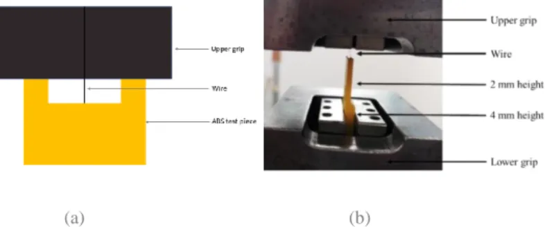
The interfacial adhesion between SE1 and ABS was tested with the test piece represented in Figure 2.3.
Figure 2.3 – Interfacial adhesion test piece, the NiTi wire is represented in grey and the yellow simulates the ABS passive part of the mesh, on the left image the red circle indicates the hole where the wire is inserted.
The wire was inserted in the hole represented in red, in Figure 2.3, of the test piece. Figure 2.4 shows the placement of the test piece on the tensile testing machine.
(a) (b)
Figure 2.4 – Schematic of the test piece (with the wire) placed on the tensile machine. On (a) is represented the assembly of the test piece on the tensile machine, this assembly allows a wire length to be secured outside the polymer matrix at the beginning of the pull-out test. On (b) is represented a photo taken after the test was finished.
This test piece was designed with two different thickness: 2 mm and 4 mm. The thinner part is where the wire is inserted, while the thicker part minimizes the risk of the gripping to affect the adhesion test, as shown in Figure 2.4. The design also comprises two cubes with 2 mm length, used to align the upper grip, in order to have always the same wire length out of the
block before starting the adhesion test.
2.2. MESH DESIGN AND PRINTING
Autodesk Fusion 360 software was used to create and model the mesh. The printer used was Ultimaker 3TM by Ultimaker. The fabricated material has a 100% infill density and 0.2 mm layer thickness. To incorporate the NiTi wire on the mesh, the original mesh design used by
9 Raminhos et al. [2] went through some adaptations, which are presented in Figure 2.5. Two “sleeves” of trapezoidal shape with a 5 mm length were placed in each extremity of the passive part.
Figure 2.5 – A unit cell with sleeves, and the sleeve in more detail. The a and b on the left Figure are length parameters The other dimensions of the sleeves were defined according to the diameter of each wire used, taking into consideration the available printing resolution. The effective values for the a and b parameters are indicated in Table 2.3.
Table 2.3 – Dimension parameters of the sleeves of the different alloys. The L and M in 0.8 mm diameter stand for Large and Medium sleeve sizes, respectively.
Dimension parameters Wire diameter (mm) 0.24 0.8 (L) 0.8 (M) 0.38 a 1.0 3.0 2.2 1.6 b 2.1 10.1 5.2 4.6
The wire was manually inserted on the sleeves. Depend on the case, it was inserted wether after the mesh had been fully printed or during a pause in the printing, keeping the print bed heated.
2.3. MESH CHARACTERIZATION – CTE EVALUATION
A schematic set up for this test piece is presented in Figure 2.6. Within a container filled with silicone oil, the mesh was constrained by two parallel plates. The temperature was measured by means of a thermocouple; whose signal was registered by the PicLog Reader software. At the same time, a photographic camera mounted above the apparatus was used to obtain images of the mesh deformation.
Figure 2.6 – Schematic of the CTE mesh testing setup [2]
The photographs obtained were analyzed with Image J software. To analyze that effect, prior to each thermal test, white circles with red dots were marked in strategic points of the mesh. The CTE measurement procedure is further explained in Appendix B.
In the next chapter, the results of all the above-referred analysis shall be exposed and discussed.
10
3
RESULTS AND DISCUSSION
Two polymers and four different alloys were characterized according to the methods described in the previous chapter.
On that basis, it became possible to proceed to the study of the incorporation of the alloys in the polymers meshes. The present chapter presents the results of such a study, and where possible draws the corresponding conclusions.
3.1. CHARACTERIZATION OF NITI WIRES
All the four wires presented have differences, whether in diameter or in behavior (SE or SME). To study these differences DSC, TMA and mechanical tests were performed. The results of these tests characterize the wires according to their phase transition temperatures, their contraction or expansion when heated, and their bending strength and shear stress adhesion forces.
3.1.1. THERMAL ANALYSIS - PHASE TRANSITIONS TEMPERATURES
The results of DSC for the NiTi wires were presented in the previous chapter (Figure 2.1). Based on a preliminary analysis, it is visible that both alloys with SME have endothermic and exothermic peaks with higher intensity compared to the peaks in alloys with SE.
Both SME alloys present, on cooling, a two-step transformation of austenite into martensite, while during heating the martensite transformation into austenite occurs in one-step for SME1, but requires two successive steps in the case of SME2. Both SE wires present a two-step transformation on cooling; furthermore, SE1 undergoes a one-two-step transformation in heating, while for SE2 alloy that transformation is two-step.
For simplification's sake, it was considered that all wires had a one-step B19’→ B2 transformation. The transformation temperatures are listed in Table 3.1.
Table 3.1 – Transformation temperatures during cooling and heating
NiTi
Transformations during cooling (ºC) Transformations during heating (ºC)
B2 → R R → B19’ B19’ → B2 Rs Rf Ms Mf As Af SE1 13.5 -24.4 -40.8 -101.4 -50 19.9 SE2 34.7 4.1 -99.1 -134.0 8.2 35.9 SME1 48.1 30.7 -30.1 -64.6 41.8 48.2 SME2 68.6 50.4 41.7 19.3 69.8 76
The transformation temperatures for both the austenite to martensite (Rs, Rf, Ms, and Mf)
and the reverse transformation (As and Af) occur at lower temperatures for SE1 and SE2. The
11 3.1.2. TENSILE TESTS
The results of the tensile test are presented in Figure 3.1. The loading path corresponds to the transformations of austenite to martensite, while unloading corresponds to the martensite to austenite transformation.
Figure 3.1 – Tensile tests of NiTi wires: A- SE1; B- SE2; C- SME1; D- SME2
Figures 3.1.A and 3.1.B present the results of respectively SE1 and SE2. Both wires, when tensile tested, show a clear superelastic behavior, with almost all the induced deformation being recovered.
Figures 3.1.C and 3.1.D represent the results for SME1 and SME2, respectively. The induced deformation up to 8 % is not entirely recovered, neither on the first cycle nor during the following ones; the remaining deformation should be recovered by SME if the samples were heated above Af.
3.1.3. THERMO-MECHANICAL ANALYSIS
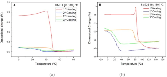
The thermo-mechanical analysis reveals the contraction and expansion associated with transformations between phases. In Figure 3.2, each cooling stage causes expansion, while inversely each heating stage leads to a contraction. The first heating stage is responsible for a considerably greater contraction than the subsequent ones, perhaps due to the residual deformation induced after the straight annealing step.
12 (a) (b)
Figure 3.2 – (a) TMA of SME1, (b) TMA of SME2. The red and orange line represents heating and the blue and green represent cooling.
Comparing SME1 with SME2, the latter has larger dimensional changes than SME1. Analyzing the first heating stage in both cases, there are expansions around 40 ºC for SME1 and around 90 ºC for SME2, followed by a large contraction. That expansion is higher for the SME2 TMA; this can be a result of the exothermic reaction, evidenced by the DSC peak of the B2 → B19’ transformation, in Figure 2.1.
Analyzing Figure 3.2, it is also notable that from the second to the third cooling stages the expansion observed becomes smaller, a phenomenon which may indicate that the wire is under functional fatigue.
The values of the linear dimensional changes and the corresponding CTE are summarized in Table 3.2.
Table 3.2 – Results of TMA analysis: linear contraction of each phase and the CTE of the austenite on each stage of cooling
Stages Dimensional linear changes (%) CTE x 10-6 /ºC
SME1 1st heating -2.1 - 2nd cooling 0.1 14.0 2nd heating -0.2 - 3rd cooling 0.1 16.4 SME2 1st heating -7.2 - 2nd cooling 2.2 33.8 2nd heating -1.6 - 3rd cooling 1.7 25.1
The first heating stage of both SME wires reveals larger contractions than the following heating cycles. Analyzing the TMA in Figure 3.1.C and 3.1.D, the first cycle presents an unrecovered deformation. The decrease in the contractions of the second and third TMA cycles is perhaps due to the unrecovered deformation by SME, which results in the circumstance that, during the remaining cycles, that deformation can only be recovered by SE.
In view of the different transition temperatures, it will be assumed, for the remainder of this work, that these alloys have different actuation temperatures and exert different forces.
13 3.1.4. FORCES INVOLVED IN EACH WIRE
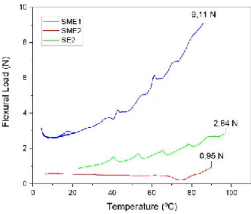
To analyze the forces involved in the transformation of each type of wire, three-point bending tests were performed according to the procedure in the previous chapter.
Figure 3.3 – Three-point bending tests on SME1, SME2, and SE2
The test was performed for SME1, SME2, and SE2 samples. Comparing the two SME alloys, that with alarger diameter reaches higher bending forces, around 9 N. Comparing the same diameter for different behaviors, the SE alloy reached higher forces, around 3N. On the SME2 line on the graph, a slight decrease in force around 70 ºC to 80 ºC is noticeable, due to the heat absorption detected by TMA around 80 ºC, where an expansion of around 1 % occurs.
For SE1, due to its small size and mesh placement, it was more convenient to perform an adhesion test, rather than a 3-point bending test. For that purpose, the wire was glued into a hole on a parallelepiped-shaped ABS sample, as shown in Figure 2.3.
Figure 3.4 – Adhesion test with three trials
With this test, the adhesive shear stress of the ABS/NiTi interface was studied. The results show an average ultimate tensile strength (UTS) of 1.02 ± 0,11 MPa.
After selecting and characterizing the alloys that will be incorporated in the composite mesh, a study of the combination between the two materials was conducted. The wires that will be used are SE1, SE2, SME1 and SME2.
14
3.2. ABS / NITI COMBINATION – INCORPORATION AND SIZING
Combining ABS with NiTi on the composite mesh implied adjustments on the mesh geometry, such as the insertion of the sleeves. These sleeves are represented in Figure 2.5 and their dimensions are represented in Table 2.3, on the materials and methods chapter.
The original thickness of the polymeric mesh was set at 1 mm. In order to evaluate if this value was the most convenient for the selected wires, tensile tests were run with elements of the passive part of the mesh, possessing three different heights: 3 mm, 1.5mm and 1 mm.
Figure 3.5 – Tensile test of ABS element mesh with three different thickness: 3 mm, 1.5 mm and 1 mm. Each thickness was tested two times, although only two were considered
The results of these tests showed that the original height, of 1 mm, has higher elongation, although it does not achieve the highest forces. Since this mesh requires greater elongations, 1 mm was the chosen thickness.
The wires were placed on the mesh in two different ways: either straightened or curved, as illustrated in Figure 3.6.
Figure 3.6 – Wire configuration in (a) the wires are in the straight configuration and in (b) are in the curved configuration.
Due to the forces that each wire exerted, the length on each wire was different. Their respective dimensions are in Table 3.3.
Table 3.3 – Wire dimensions, considering their positioning
SE1 SE2 SME1 SME2
Length of wire straightened (cm) 1.5 1.5 - -
Length of wire curved (cm) - 2.0 1.8 2.0
Two main problems were found during wire positioning: not only was it difficult to cut all the wires with the exact same length, but the cavity where the wire would be placed tended to close prematurely, due to the lowering of the polymer flow. These problems were later found to
15 impact the activation and closing of the re-entrant angle, during the deformation of the composite meshes.
3.3. DUAL POLYMER MATERIAL MESH PRINTING
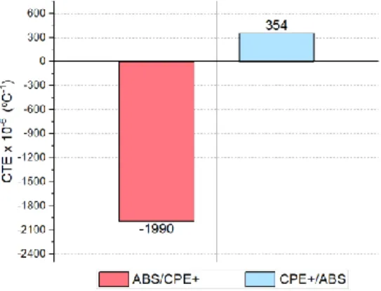
Only one polymer is needed for the passive part of the mesh. To decide which one should be used, meshes with ABS/CPE+ (ABS in passive part and CPE+ on the active part), and meshes with CPE+/ABS (the opposite configuration) were printed and tested for the determination of the corresponding CTE values.
Figure 3.7 – Thermal testing of ABS/CPE+ and CPE+/ABS meshes. These tests were performed in a range of 28 ºC to 120 ºC.
Both meshes were tested between 28 ºC and 120 ºC. ABS/CPE+ demonstrated a contraction, resulting in a negative CTE, while the CPE+/ABS mesh demonstrated an expansion of the unit cells, resulting in a positive CTE. Hence for subsequent work, ABS was selected for the passive part of the mesh.
3.4. MONO-MATERIAL ABS AND WITHOUT AN ACTIVE PART MESHES.
Prior to combining the ABS passive part and the NiTi alloy active part, it is necessary to test the behavior of the ABS mono-material mesh, as well as that partial mesh formed by just the passive part of the structure.
Figure 3.8.shows the results of such characterization, compared to the equivalent result for a PVA/NYLON mesh, as obtained from the literature [2].
16 Figure 3.8 – CTE of PVA/Nylon, Mono-material ABS full mesh, and passive partial mesh
Tested between room temperature and 85 ºC, the PVA/NYLON mesh exhibits a negative CTE of -1568× 10-6 ºC-1, while both the mono-material ABS full mesh and passive partial mesh,
exhibits a positive CTE ( 93 × 10-6 ºC-1 and 95 × 10-6 ºC-1, respectively), confirming that none of
the latter displays an anepectic behavior.
The ABS mono-material full and partial meshes are taken as a baseline. If the meshes with the combination ABS/NiTi have a similar CTE to these baselines, that implies that the ABS/NiTi composite does not exhibit anepectic behavior; therefore, the contribution of the shape memory alloy may be considered null.
One of the problems that arose concerned the heating rate achieved during the thermal tests. In an attempt to minimize this problem, a mono-material ABS full mesh was used as means of finding the position of the hot plate insuring a more reproducible result.
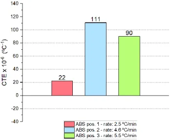
Figure 3.9 – CTE of Mono-material ABS full mesh on different rates of heating
This showed that the heating rate has a major influence on the CTE values determined. Since the larger CTE result was achieved while using the hot plate in position 2, this was chosen for further studies, resulting in an average heating rate of 4 ° C / min.
17
3.5. TESTING OF ABS/NITI COMPOSITE MESHES
After characterizing the wires, selecting the polymeric passive part, and knowing the effect of a mesh without any intervention of the wire, the combinations between the ABS and NiTi wires will be studied and tested.
The combination between the two materials leads to seven different meshes, that comprehend different ways of configuring the wires and different mesh geometries. The seven meshes are presented with their respective abbreviations in Table 3.4.
Table 3.4 – Designations of the abbreviation of the studied composites Abbreviation Description
ABS + SE1 Composite with ABS and 0.24 mm diameter SE NiTi alloy ABS + SE2 (S) Composite with ABS and 0.38 mm diameter SE straight NiTi alloy ABS + SE2 (C) Composite with ABS and 0.38 mm diameter SE curved NiTi alloy ABS + SME1 (L) Composite with ABS and 0.8 mm diameter SME NiTi alloy with Larger
sleeves
ABS + SME1 (M) Composite with ABS and 0.8 mm diameter SME NiTi alloy with Medium sleeves
ABS + SME2 Composite with ABS and 0.38 mm diameter SME NiTi alloy ABS + SE2 (C) +
SME2
Composite with ABS, with 0.38 mm diameter SE curved in one direction and 0.38 mm diameter SME alloy on the other direction
The differences between the seven different meshes permitted a study of the impact on the composite mesh behavior of the following aspects:
1. Wire diameter; 2. Wires configuration;
3. Separate effects of superelasticity and shape memory; 4. Combined effects of SE and SME;
5. Sleeve geometry;
6. Heating and cooling cycles;
7. Activation temperature and plastic flow during heating;
In what follows, graphs containing CTE values, together with images of the unit cell at 90 ºC, shall be shown as a basis for discussion. Due to space constraints, the corresponding images illustrating the initial and final stages of the meshes are contained in Appendix C.
18 3.5.1. EFFECT OF WIRE DIAMETER
As mentioned in the previous chapter, four wires were selected with three different diameters. This section discusses the effect of wire diameter on the behavior of the mesh.
Figure 3.10 – CTE of the meshes with SE and SME wires
It should be noted that, regardless of the SE or SME of the wire, a different diameter implies differences in sleeve design: a thicker wire implies sleeves with larger dimensions, that result in more marked motion restrictions and subsequently a smaller allowance for mesh shrinkage.
As can be seen from Figure 3.10, ABS + SME1 (L), which contains larger sleeves, show less shrinkage if comparing to ABS + SME2, resulting in a less negative CTE. Although the meshes with SE wires have smaller sleeves, they do not exhibit a negative CTE; however, as shall be discussed below, this is not a consequence of the wire diameter, but of the wire configuration.
3.5.2. EFFECT OF WIRES CONFIGURATION
As evidenced in Figure 3.6, two alternative wire configurations were considered – curved and straight. For a straight configuration, the wires need to be placed during a pause in the printing sequence of the mesh. For a curved configuration, the wires are placed after the mesh is printed. When the wires are inserted curved, their retraction allows them to push the sleeves, causing the re-entrant structure to close (more shrinkage); on the other hand, when the wires are placed straight, their retractions pulls the sleeves, causing the re-entrant structure to open (more expansion).
The SME wires show that effect above room temperature, so when they contact the hot print bed, the martensite to austenite transformation takes place and the SME during the thermal test will be less pronounced, therefore these wires should only be inserted after the mesh printing. By inserting the SE wires after the mesh printing, it is minimized the risk of the actuation forces be increased, due to the increase of the critical stress with temperature.
19 To study the effect of the wire configuration it was chosen the SE2, due to the smaller diameter of the SE1.
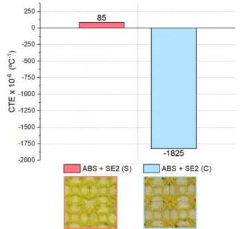
Figure 3.11 – CTE of the meshes with SE2 wire with different configurations
The results show that only with a curved wire configuration, can NTE can be attained. This can be a result of two factors: when curved, the wires exert a larger force than when they are placed straight; concurrently, the wire on the ABS + SE2 (C) mesh is longer than in ABS + SE2 (S). Therefore, it is possible to tailor the CTE of the mesh with SE2 by changing the position of the wires.
For an anepectic mesh behavior to take place, the active part must expand when heated. The intrinsic CTE of NiTi wires is smaller than that of ABS. To achieve higher expansions on the active part, the strategy used was to introduce a lengthy wire, through the use of a curved configuration. The DSC results of these wires show two transformations during heating, from B19' → R' and from R' →B2. The superelasticity domain appears when the wires are heated above Af, in this case above 35.9 ºC, in which cases the curved wires undergo a transformation strain.
3.5.3. SEPARATE EFFECTS OF SUPERELASTICITY AND SHAPE MEMORY OF ACTIVE ELEMENTS
In the previous section, the effect of a curved wire on the mesh was studied in comparison with that of a straightened wire. In this section, the differences arising from the use of a SE (SE2) or an SME wire (SME2), both with the same curved configuration, the same length, and the same diameter, are analyzed.
20 Figure 3.12 – CTE of the mesh with SME2 and the mesh with SE2, with a curved configuration
For this comparison, the ABS + SE2 (C) and ABS + SME2 meshes, both with an anepectic behavior, have been chosen. The CTE value for the second mesh is more negative, at -2656 × 10-6 ºC-1 than that observed for the first mesh ( -1825 × 10-6 ºC-1).
Although the SE2 wire presents a higher bending load (as shown in Figure 3.3), SME2 exhibits a shape memory effect. The TMA results show that when heated for the first time the wires have a contraction of 7.2 %. When these are incorporated on a mesh and this is thermally tested, the contraction, because of the curved configuration, causes the wire to straighten and in turn leads to the expansion of the active part of the mesh, causing the overall mesh contraction.
3.5.4. COMBINED EFFECTS OF A SUPERELASTICITY AND SHAPE MEMORY OF ACTIVE ELEMENTS
The previous results showed that a mesh reinforced with SME wires presents an anepectic behavior, regardless of the wire diameter, and that it is possible for a mesh with SE wires to also be anepectic, on the condition of a curved wire configuration.
Figure 3.13 – ABS + SE2 (C) mesh, the axes indicate the direction that each wire was placed
In this section, the results concerning a hybrid mesh which along one direction contains curved SE2 wires and straight SME2 wires along a perpendicular direction, as indicated in Figure 3.13, are discussed.
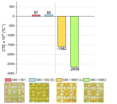
21 Figure 3.14 – CTE of the mesh combining SE2 and SME2, and the meshes with SME2 and SE2 separately
When both types of wires are thus combined in the same mesh, the anepectic behavior is also observed, but with an even more negative value of CTE. Of all the meshes in this work, this was the mesh that achieved the extreme CTE result, at -3008 × 10-6 ºC-1. The ABS + SE2 (C) +
SME2 mesh has two stages of actuation that correspond to the martensite to austenite transformations occurring sequentially in SE2 and SME2.
The austenite to martensite transformation occurs close to room temperature for SE2 and above 69,8 ºC (Af) for SME2. The active part with SE2 wires straightened first, then the SME2
wires straightened in the other direction. This effect allowed the re-entrant structure to undergo a more pronounced shrinkage.
3.5.5. EFFECT OF SLEEVE GEOMETRY
TMA results for the SME wires showed that the contractions during the first heating stage are larger than those happening subsequently. As a result, the shape memory behavior has a larger effect on the first heating stage than afterwards. As an attempt to try to re-use wires that had already undergone a heating cycle, the design of the ABS + SME1 mesh was changed to incorporate smaller sleeves. For this study, the SME1 wire was chosen, due to the large motion restriction that its sleeves had induced.
22 Figure 3.15 – CTE of meshes with SME1containing larger (L) and medium (M) sleeves
The results from Figure 3.15 show that even by modifying the mesh design, it was not possible to attain similar CTE values with a re-used wire. The mesh with larger sleeves showed a CTE of -1582 × 10-6 ºC-1, but this value became -1142 × 10-6 ºC-1 when the medium-sized sleeves
were introduced.
3.5.6. EFFECT OF HEATING AND COOLING CYCLES
While for meshes containing SME1 wires the sleeves design was changed, in an effort to re-use the wires, for the meshes with SME2 wires the same attempt was undertaken via three successive heating and cooling cycles.
Moreover, performing such cycles with an ABS + SME2 mesh also served to study the impact of the phase transformations in each cycle, and of the dimensional linear changes related to those phases.
23 The heating stages were performed between 28 ºC and 90 ºC, and the cooling stages occurred between 90 ºC and 28 ºC. It was expected that on heating the mesh would present a negative CTE, while during cooling that parameter would become positive. However, the results presented in Figure 3.16 show that only during the first heating stage is the CTE negative, and it becomes steadily positive for the following cooling and heating cycles.
During the first heating stage, the mesh shrinks until 90 ºC. The Tg of the polymer is
exceeded, causing the polymer to flow and irreversible deformations on the structure. The TMA results in Figure 3.2 show that each heating stage is associated with an expansion, and each cooling is associated with a contraction. These linear dimensional changes could demonstrate an impact on the mesh; however, the thermal testing results show an approximately uniform CTE value from the first cooling stage to the end of the test. Thereby, these expansions did not contribute to recovering part of the deformation imposed.
Another result is the CTE value of the first cycle, at -726 × 10-6 ºC-1. This value differs
significantly from that achieved by the other ABS + SME2 mesh, of -2656 × 10-6 ºC-1. The
difference between the two experiences may be a result of the hot plate conditions, since the equipment underwent damage prior to the last thermal test, which caused an inhomogeneous heating conditions, with no opportunity to repeat the experiment.
3.5.7. ACTIVATION TEMPERATURE AND PLASTIC FLOW DURING HEATING
From the seven different meshes, five exhibited negative values of CTE. To evaluate the initial point of the mesh activation, photographs of each mesh from 30 ºC to 75 ºC were analyzed.
Figure 3.17 – Activation temperatures of the different composite meshes. Partial enlargement of the graph is also shown
Each line in the graph shown in Figure 3.17 corresponds to the mesh shrinkage as a function of the temperature range. The activation temperature corresponds to the point when the CTE values become negative when the shrinkage is below 0%. These temperatures are described in Table 3.5.
24 Table 3.5 – Activation temperatures
ABS + SE2 (C) ABS + SME1 (L) ABS + SME1 (M) ABS + SME2 ABS + SE2 (C) + SME2 Ta (ºC) 63 38 38 57 42
Comparing the DSC results it was expected that the first meshes to be activated would be those containing SE2 wires, followed by the meshes with SME1 and then those with SME2. Instead, the results in Table 3.5 show that mesh ABS + SE2 (C) was that with a higher activation temperature.
The forces imposed by the curved SE2 wire, are high, and consequently, the stiffness of the ABS + SE2 (C) mesh is increased, making it more difficult to activate. However, when SE2 is combined on the same mesh with a SME2 wire (ABS + SE2 (C) + SME2), it results in a lower activation temperature than that for ABS + SE2 (C), due to the polymer’s decreased stiffness.
The activation temperature marks the onset of a negative CTE. All the results showed previously discussed pertained to meshes tested between 28 ºC and 90 ºC. To observe the plastic flow during heating, Figure 3.18 shows the CTE values for three temperature ranges.
Figure 3.18 – Plastic flow during heating of the mesh with SME2
The plastic flow was analyzed on mesh ABS + SME2, where a mesh activation temperature of 57ºC was attained. The mesh decreases its CTE when the temperature increases, and even below the polymer’s Tg the mesh presented a significantly negative CTE.
3.6. FINITE MODEL ANALYSIS
To support the experimental results, an FE analysis was performed. The software used was the same for modeling the mesh, Autodesk Fusion 360.
The passive part of the mesh was considered to be made from ABS, and due to the lack of NiTi alloys on the program, a Nickel-Copper Alloy 400 was considered for the active part. A thermal stress simulation test was performed, with 90ºC of applied temperature to all the mesh, and a 250 N load applied to the active part of the mesh, along with both the x and y directions. To induce a constraint in the middle, the central unit cell was joined with two elements of ABS, creating a point where the x, y and z directions are fixed.
25 The displacements results are represented in Figure 3.19. For representative effects, the mesh scale on those simulations is 100 times larger.
Figure 3.19 – FE analysis of the displacements in x, y and z directions
The results of the FE analysis show that the mesh undergoes positive and negative displacements.
The presented simulation results are not in agreement with the thermal experimentally observed behavior presented above.
These results may be influenced by differences in mesh geometry (e.g. the absence of sleeves), differences in wire geometry, the circumstance that thermophysical data from a nickel-copper alloy had to be used in the simulation to represent the mesh’s active part, due to the unavailability of NiTi as an option, and the limitations on the design of the hinges in this model.
26
4
CONCLUSIONS AND FUTURE
PERSPECTIVES
This thesis was developed as a sequence of a work performed by Raminhos et al. [2], which developed a new type of mesh – called anepectic – where, through adequate balancing of intrinsic properties of the constituents, a composite resulting from a combination of two polymers simultaneously exhibited negative values for the coefficient of thermal expansion and the Poisson’s ratio. In this thesis, one of the polymers in the mesh has been replaced with a NiTi alloy, and the performance of such combination subject to evaluation.
Two polymers, ABS and CPE+, were considered for incorporation in the mesh. When combining the two it was concluded that only with ABS on the passive part of the mesh was it possible to attain a negative CTE. For that reason, ABS was chosen as the polymeric (passive) mesh constituent. For the active constituent, four NiTi wires were considered, with different diameters and behaviors. Besides the superelastic or shape memory traits of the wires used, the combination of ABS and NiTi wires resorted to two alternative configuration strategies, one in which the wires were curved and the other with the wires straightened.
The results of the meshes’ thermal testing are all summarized in Figure 4.1.
Figure 4.1 – CTE of the most relevant meshes on this work
The mono-material full and partial (passive) ABS structures showed a positive CTE. A similar result observed for an ABS / NiTi mesh would mean that the metallic contribution to an anepectic effect was non-existent.
Of the seven composite meshes presented in this work, five presented the desired anepectic effect. The other two composite meshes presented a positive CTE, as a consequence of the wire curved configuration. Therefore, by changing the wire configuration from straight to curved, the CTE value could be tailored. Other parameters that revealed to have an impact on the mesh behavior were the wire diameter, the mesh sleeve design and the intrinsic behavior of the wire.
The impact of the diameter revealed to be larger on meshes with SME wires, while for SE wires the CTE results (of ABS + SE1 and ABS + SE2 (S)) revealed to be similar. Between the ABS + SME1 (L) and ABS + SME2 meshes, the latter presented a higher shrinkage and a
![Figure 1.2 – Metamaterials on Ai and Gao work [31][32]](https://thumb-eu.123doks.com/thumbv2/123dok_br/18158690.872660/25.892.154.740.104.361/figure-metamaterials-on-ai-and-gao-work.webp)