Dio go Mato s Ferreira
Licenciado em Ciências da Engenharia Eletroté cnica
e de Computadores
Framewo rk fo r Io T Servic e Oriented Systems
Dissertação para obtenção do Grau de Mestre em
Engenharia Eletroté cnica e de Computadores
Orientador: Douto r Ricardo Jardim Go nçalves, Profe ssor Associado com
Agregação , FCT-UNL
Co -orientador: Jo ão Filipe dos Santos Sarraipa, Professor Auxiliar Convidado, FCT-UNL
Júri:
Presidente : Doutor Luis Augusto Bica Gomes de Oliveira
– FCT/UNL
Argue nte:
Vogal:
Doutor Tiago Oliveira Mac hado de Figue iredo Cardo so
– FCT/UNL
Framework for IoT Service Oriented Systems
Copyright © Diogo Matos Ferreira, Faculdade de Ciências e Tecnologia, Uni-versidade Nova de Lisboa.
Abstract
The forth industrial revolution is here, and with it Industry 4.0, which translates in many changes to the industry. With the introduction of paradigms like Internet of Things, Cyber Physical Systems or Cloud Computing, the so called Smart Factories are becoming a main part of today’s manufacturing systems. The vf-OS Project, where this thesis falls, intends to be an Open Operating System for Virtual Factories where the overall network of a collaborative manufacturing and logistics environment can be managed and thus enabling humans, applications and devices to communicate and interoperate in an interconnected operative environment.
This thesis intends to contribute to the vision that any kind of sensor or actuator plugged to the virtual factory network, becomes promptly accessible in the operative environment and the services that it provides can be accessed and used by any API composing the system. Finally, it also aims to prove that an IoT Service Oriented Sys-tem constituted of open software components can be of great assistance and provide numerous contributions to the emerging Industry 4.0 and consequently to the Factories of the Future.
With that aim, this thesis will focus on the development of two out of five inter-connected applications that answer not only to different use case scenarios presented in the vf-OS but also provide solutions to answer a practical agriculture scenario, which uses mainly IoT devices and other cutting-edge technologies like cloud compu-ting and FIWARE.
Resumo
A quarta revolução industrial chegou, e com ela a Indústria 4.0, o que se traduz em inúmeras alterações na indústria. Com a introdução de paradigmas como a Internet of Things, Cyber Physical Systems ou Cloud Computing, as assim denominadas Smart Factories (Fábricas Inteligentes), estão-se a tornar cada vez mais uma parte fundamen-tal dos sistemas de manufatura atuais. O projeto vf-OS, no qual esta tese se insere, tem como objetivo o desenvolvimento de um Sistema Operativo aberto para Fábricas Vir-tuais, que pretende ser um quadro capaz de gerir a rede global de um ambiente cola-borativo de produção e logística e assim permitir que humanos, aplicações e dispositi-vos comuniquem e operem num ambiente operacional interligado, e é exatamente so-bre quadro que esta tese incide.
Esta tese pretende contribuir para a visão de que qualquer sensor ou atuador co-nectado à rede da fábrica virtual se torna prontamente acessível através do ambiente operativo da fábrica e todos os serviços por ele prestados podem ser acedidos por qualquer API que componha o sistemas. Finalmente esta tese pretende ainda provar que os sistemas orientados a serviços IoT, utilizando software livre, podem servir de grande ajuda e fornecer inúmeras contribuições para a emergente Industria 4.0 e con-sequentemente para as Fábricas do Futuro.
Para isso esta tese consiste no desenvolvimento de duas de cinco aplicações inter-ligadas que pretendem responder não só a diferentes “use case scenarios” apresenta-dos no projeto vf-OS como ainda fornecer soluções para um cenário prático de agricul-tura, recorrendo principalmente ao uso de dispositivos IoT e a outras tecnologias de ponta como cloud computing e FIWARE.
Contents
CONTENTS ... XI
LIST OF FIGURES ... XV
LIST OF TABLES ... XIX
ACRONYMS ... XXI
1 INTRODUCTION ... 1
1.1 MOTIVATION AND BACKGROUND ... 1
1.2 GOALS AND CONTRIBUTIONS ... 4
1.3 THESIS ORGANIZATION ... 5
2 STATE OF THE ART ... 7
2.1 KERNEL ... 7
2.1.1 Kernel’s components...10
2.1.2 Monolithic Kernel ...11
2.1.3 Microkernels ...12
2.1.4 Hybrid Kernels ...13
2.1.5 Exokernels ...14
2.1.6 Kernel Architectures Summary ...15
2.2 FACTORIES OF THE FUTURE ... 16
2.3 WEB SERVICES FOR INDUSTRIAL INTERNET OF THINGS ... 20
2.4 FIWARE ... 24
2.5 IOT AS A SERVICE ... 26
2.5.1 Model ...26
2.5.2 Framework ...27
2.5.3 Mashup ...29
2.7 RESEARCH QUESTION AND HYPOTHESIS ... 32
3 PRACTICAL FRAMEWORK ... 33
3.1 VF-OS(VIRTUAL FACTORY -OPERATING SYSTEM) ... 34
3.2 USE CASE SCENARIOS ... 36
3.3 PRACTICAL SCENARIO ... 39
3.4 FROM THE SCENARIOS TO THE APPLICATIONS ... 41
3.5 TECHNOLOGIES ... 44
3.5.1 Docker ... 45
3.5.2 FIWARE Orion Context Broker ... 46
3.5.3 FIWARE Short Time Historic (STH) – Comet ... 53
3.6 SUMMARY ... 57
4 DEVELOPED APPLICATIONS ... 59
4.1 APPLICATIONS ENTITIES ... 60
4.2 VORDER... 62
4.3 VFNEGOTIATION ... 66
4.4 APPLICATIONS DEMO ... 70
4.4.1 vOrder – Choose User ... 71
4.4.2 vOrder – Farmer User Interface ... 72
4.4.3 vOrder – Main Interface ... 75
4.4.4 vOrder – Dispatch Order ... 78
4.4.5 vOrder – Truck Creation Tab ... 79
4.4.6 vOrder – Existent Trucks Tab ... 86
4.4.7 vOrder – Generate Values Tab ... 89
4.4.8 vOrder – Check Transport Tab ... 95
4.4.9 vOrder – Delete Truck Tab ... 102
4.4.10 vOrder – Manage Truck Tab ... 103
4.4.11 vfNegotiation – Choose User Interface ... 108
4.4.12 vfNegotiation – Farmer User Interface ... 109
4.4.13 vfNegotiation – Farmer Main Interface ... 111
4.4.14 vfNegotiation – Farmer Main Interface: Add Fruit Tab ... 112
4.4.15 vfNegotiation – Farmer Main Interface: Check Fruit Tab ... 114
4.4.16 vfNegotiation – Farmer Main Interface: Update Fruit Tab ... 117
4.4.17 vfNegotiation – Farmer Main Interface: Production Values Tab ... 121
4.4.18 vfNegotiation – Buyer Main Interface ... 123
4.4.19 vfNegotiation – Buyer Main Interface: Manual Search Tab ... 124
4.4.20 vfNegotiation – Buyer Main Interface: Automatic Search Tab ... 127
4.4.21 vfNegotiation – Buyer Main Interface: Order Draft ... 131
5.2 FUTURE WORK ... 138
BIBLIOGRAPHY ...141
List of Figures
FIGURE 2.1-KERNEL POSITION IN THE OPERATIVE SYSTEM (KERNEL LAYOUT,2008) ... 8
FIGURE 2.2–MONOLITHIC KERNEL ARCHITECTURE (KERNEL MONOLITHIC,2008) ... 11
FIGURE 2.3–MICROKERNEL ARCHITECTURE (KERNEL MICROKERNEL, 2008) ... 12
FIGURE 2.4–HYBRID KERNEL ARCHITECTURE (KERNEL HYBRID, 2008) ... 13
FIGURE 2.5–EXOKERNEL ARCHITECTURE (KERNEL EXOKERNEL,2013) ... 14
FIGURE 2.6–MONOLITHIC KERNEL,MICROKERNEL AND HYBRID KERNEL COMPARISON (OS STRUCTURE, 2008) ... 15
FIGURE 2.7–CHANGES IN MANUFACTURING PARADIGMS.ADAPTED FROM(S. J. HU ET AL., 2011) ... 16
FIGURE 2.8–FIFTEEN COMPONENTS OF A FACTORY OF THE FUTURE.ADAPTED FROM (LUETH,2015) ... 19
FIGURE 2.9–IOT MODEL: KEY CONCEPTS AND INTERACTIONS.ADAPTED FROM (BAUER ET AL., 2011) ... 27
FIGURE 2.10–OPENIOT FRAMEWORK.ADAPTED FROM (KIM & LEE, 2014) ... 28
FIGURE 2.11–IOTMAAS(IOTMASHUP AS A SERVICE) CONCEPT.ADAPTED FROM (IM ET AL.,2013) ... 30
FIGURE 3.1–PRACTICAL SCENARIO ILLUSTRATION ... 40
FIGURE 3.2–USE CASE SCENARIOS APPLICATIONS APPLIED TO THE PRACTICAL SCENARIO ... 43
FIGURE 3.3–CONTAINER VS VIRTUAL MACHINE COMPARISON (DOCKER,2017) ... 45
FIGURE 3.4–NGSI10SCHEMA OF REST RESOURCES (NGSI10, 2014) ... 47
FIGURE 3.5–NGSI9SCHEMA OF REST RESOURCES (NGSI9, 2014) ... 49
FIGURE 3.6–NGSI9/NGSI10CONTEXT ELEMENT (ENTITY) SCHEMATIZED STRUCTURE ... 52
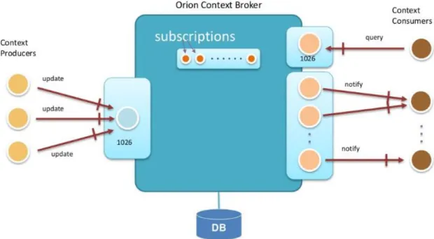
FIGURE 3.7–ORION CONTEXT BROKER IN A NUTSHELL (FIWARE - ORION CONTEXT BROKER, 2014) ... 53
FIGURE 3.8–ORION CONTEXT BROKER +STH WORKING SCHEMATIC ... 56
FIGURE 3.9–SCENARIO +VAPPS +GENERIC ENABLERS USE SUMMARY ... 57
FIGURE 4.1– VF-OS INTERCONNECTED APPS DEVELOPED WITHIN THE MASTER THESIS WORKGROUP ... 59
FIGURE 4.3– VORDER APPLICATION SCHEMATIC ... 65
FIGURE 4.4– VFNEGOTIATION INTERFACES ... 66
FIGURE 4.5– VFNEGOTIATION APPLICATION SCHEMATIC ... 69
FIGURE 4.6–RUNNING FIWAREORION CONTEXT BROKER THROUGH DOCKER ... 70
FIGURE 4.7–RUNNING FIWARESHORT TERM HISTORIC THROUGH DOCKER ... 71
FIGURE 4.8–CHOOSE USER INTERFACE ... 72
FIGURE 4.9– VORDER:FARMER USER INTERFACE ... 73
FIGURE 4.10–FARMER USER INTERFACE:ERRORS INTERFACE ... 73
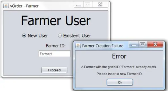
FIGURE 4.11–FARMER USER INTERFACE:FARMER CREATION ERROR ... 74
FIGURE 4.12–FARMER USER INTERFACE:INEXISTENT FARMER ERROR ... 74
FIGURE 4.13– VORDER MAIN INTERFACE FOR TRANSPORT PROVIDERS ... 75
FIGURE 4.14– VORDER MAIN INTERFACE FOR BUYERS ... 76
FIGURE 4.15– VORDER MAIN INTERFACE FOR FARMERS ... 77
FIGURE 4.16– VORDER FARMER:DISPATCH ORDER INTERFACE ... 78
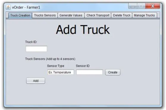
FIGURE 4.17–TRUCK CREATION: ONE SENSOR ... 80
FIGURE 4.18–TRUCK CREATION: FOUR SENSORS ... 81
FIGURE 4.19–TRUCK CREATION:EMPTY TRUCK IDMESSAGE ... 82
FIGURE 4.20–TRUCK CREATION:SUCCESS MESSAGE ... 83
FIGURE 4.21–TRUCK CREATION:DELETE TRUCK SUCCESS MESSAGE ... 84
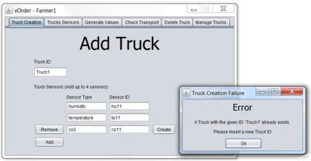
FIGURE 4.22–TRUCK CREATION:FAILURE MESSAGE ... 85
FIGURE 4.23–TRUCK CREATION TAB:TRANSPORT PROVIDER USER ... 86
FIGURE 4.24–EXISTENT TRUCKS TAB:TRUCKS LIST... 87
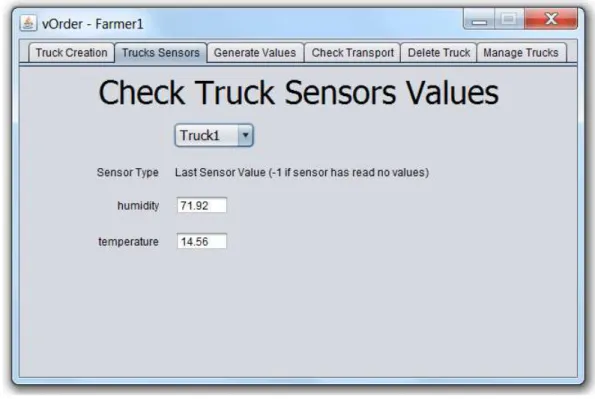
FIGURE 4.25–EXISTENT TRUCKS TAB: LAST READ SENSOR VALUES FOR A TRUCK ... 88
FIGURE 4.26–EXISTENT TRUCKS TAB:SENSORS WITH NO VALUES EXAMPLE ... 89
FIGURE 4.27–RANDOM GAUSSIAN DISTRIBUTION ... 91
FIGURE 4.28–GENERATE VALUES TAB:GENERATING 30 VALUES OVER 1 MIN ... 93
FIGURE 4.29–GENERATE VALUES TAB:VALUES GENERATION SUCCESS MESSAGE ... 94
FIGURE 4.30–GENERATED VALUES TAB:EMPTY FIELD ERROR MESSAGE ... 94
FIGURE 4.31–CHECK TRANSPORT TAB:BUYER USER ... 95
FIGURE 4.32–CHECK TRANSPORT TAB:INEXISTENT ORDER ERROR MESSAGE ... 96
FIGURE 4.33–CHECK TRANSPORT TAB:FARMER USER ... 97
FIGURE 4.34–CHECK TRANSPORT TAB:NO TRANSPORTATION PERFORMED MESSAGE ... 97
FIGURE 4.35–CHECK TRANSPORT TAB:NORMAL TRANSPORT CONDITIONS VIEW ... 98
FIGURE 4.36–CHECK TRANSPORT TAB:TRANSPORT CONDITIONS RATED AS BAD ... 101
FIGURE 4.37–DELETE TRUCK TAB:SUCCESS MESSAGE ... 102
FIGURE 4.38–DELETE TRUCK TAB:TRAVELLING TRUCK ERROR ... 103
FIGURE 4.39–MANAGE TRUCKS TAB ... 104
FIGURE 4.40–MANAGE TRUCKS TAB:ARRIVED BUTTON ... 105
FIGURE 4.41–MANAGE TRUCKS TAB:EDIT SENSORS BUTTON ... 105
FIGURE 4.42–MANAGE TRUCKS TAB:EDIT TRUCK SENSORS ... 106
FIGURE 4.43–MANAGE TRUCKS TAB:EDIT TRUCK SENSORS TYPE ... 107
FIGURE 4.44–MANAGE TRUCKS TAB:EDIT TRUCK SENSORS ID ... 108
FIGURE 4.47– VFNEGOTIATION:FARMER MAIN INTERFACE ... 111
FIGURE 4.48–ADD FRUIT TAB:EXISTENT FRUIT ERROR MESSAGE... 112
FIGURE 4.49–ADD FRUIT TAB:FRUIT CREATION ... 113
FIGURE 4.50–CHECK FRUIT TAB ... 114
FIGURE 4.51–CHECK FRUIT TAB:FRUIT NAME LIST ... 115
FIGURE 4.52–CHECK FRUIT TAB:FRUIT BREED LIST ... 115
FIGURE 4.53–CHECK FRUIT TAB:FRUIT INFORMATION PROVIDED ... 116
FIGURE 4.54–CHECK FRUIT TAB:0’S IN THE INFORMATION... 117
FIGURE 4.55–UPDATE FRUIT TAB ... 117
FIGURE 4.56–UPDATE FRUIT TAB:ERRORS INTERFACE... 118
FIGURE 4.57–UPDATE FRUIT TAB:SEARCH DONE ... 119
FIGURE 4.58–UPDATE FRUIT TAB:FRUIT UPDATE FAILURE ... 119
FIGURE 4.59–UPDATE FRUIT TAB:UPDATE FIELDS ... 120
FIGURE 4.60–UPDATE FRUIT TAB:FRUIT UPDATE SUCCESS ... 121
FIGURE 4.61–PRODUCTION VALUES TAB ... 122
FIGURE 4.62–PRODUCTION VALUES TAB:FRUIT’S LAST PRODUCTION VALUES ... 123
FIGURE 4.63– VFNEGOTIATION:BUYER MAIN INTERFACE ... 123
FIGURE 4.64–MANUAL SEARCH TAB:AVAILABLE FILTERS ... 124
FIGURE 4.65–MANUAL SEARCH TAB:FILTERS AND NO FILTERS RESULTS ... 126
FIGURE 4.66–MANUAL SEARCH TAB:NO FARMER ERROR MESSAGE ... 127
FIGURE 4.67– VFNEGOTIATION BUYER INTERFACE:AUTOMATIC SEARCH TAB ... 128
FIGURE 4.68–AUTOMATIC SEARCH TAB:AVAILABLE FILTERS ... 129
FIGURE 4.69–AUTOMATIC SEARCH TAB:FILTERS RESULTS COMPARISON ... 131
FIGURE 4.70– VFNEGOTIATION:BUYER ORDER DRAFT ... 132
List of Tables
TABLE 3.1–ANALOGY BETWEEN SOFTWARE OS AND VF-OSMANUFACTURING OS. ... 35
TABLE 3.2– VF-OSGENERIC USE CASE SCENARIOS. ... 37
TABLE 3.3–SCENARIO STEPS EXPLANATION. ... 40
TABLE 3.4–NGSI10 SPECIFIC FUNCTIONS. ... 48
TABLE 3.5–NGSI9 SPECIFIC FUNCTIONS. ... 50
TABLE 3.6–NGSI9/NGSI10CONTEXT ELEMENT (ENTITY) STRUCTURE. ... 51
TABLE 3.7–FIWARESTH HISTORICAL AGGREGATION METHODS. ... 55
TABLE 4.1–LIST OF ENTITIES. ... 60
TABLE 4.2–TRUCK CREATION EXAMPLE ONE. ... 82
TABLE 4.3–TRUCK CREATION EXAMPLE TWO ... 84
TABLE 4.4–TRUCKS CREATED FOR EXEMPLIFICATION PURPOSES. ... 87
TABLE 4.5–MEAN AND DEVIATION VALUES USED FOR EACH SENSOR ... 91
TABLE 4.6–BOUNDARIES FOR EACH SENSOR AND PERCENTAGE OF VALUES FALLING UNDER EACH ONE ... 92
TABLE 4.7–BOUNDARIES OF THE TRANSPORT CONDITIONS EVALUATION ... 100
TABLE 4.8–BOUNDARIES OF THE TRANSPORT CONDITIONS EVALUATION FOR CO2(CONCENTRATION). ... 101
TABLE A.1–FLEET ENTITY. ... 147
TABLE A.2–TRUCK ENTITY. ... 148
TABLE A.3–SENSOR ENTITY. ... 148
TABLE A.4–SUBSCRIPTION (TRUCK STATE)ENTITY. ... 150
TABLE A.5–SUBSCRIPTION (SENSOR VALUES)ENTITY. ... 150
TABLE A.6–ORDER ENTITY... 151
TABLE A.7–FARMER ENTITY. ... 152
Acronyms
FoF Factories of the Future
IoT Internet of Things
CPS Cyber Physical Systems
CC Cloud Computing
SF Smart Factories
vf-OS virtual factory – Operating System
vf-SK virtual factory – System Kernel
vf-AP virtual factory - Application Programming Interface
vf-W virtual factory - Middleware
API Application Programming Interface
AI Artificial Intelligence
XaaS Anything as a Service
IT Information Technology
OS Operating System
I/O Input / Output
CPU Central Processing Unit
IPC Inter-Process Communication
IIoT Industrial Internet of Things
RFID Radio-Frequency Identification
SOA Service-Oriented Architecture
UDDI Universal Description, Discovery and Integration
WS Web Services
IaaS Infrastructure as a Service
PaaS Platform as a Service
SaaS Software as a Service
IoTaaS IoT as a Service
IoTMaaS IoT Mashup as a Service
ICT Information and Comunication Technology
M2M Machine to Machine
GE Generic Enabler
VM Virtual Machine
NGSI Next Generation Services Interface
REST REpresentational State Transfer
HTTP HyperText Transfer Protocol
DB DataBase
1
Introduction
In this chapter, a brief introduction on the situation under which this the-sis is developed is presented. This situation is the past and current development of the factories, manufacture and agriculture worlds. All of these big industrial worlds are constantly in development and modernization, and a new industrial revolution is arriving, getting together all these previously distinct worlds and turning them into one large interconnected industrial world. While the
Europe-an vf-OS project aims to provide Europe-answers to the combination of all these big
in-dustrial worlds, this thesis’ goal is to provide small tools, to help the vf-OS
an-swer the requirements of the interconnected industry.
After the presentation of the background of the vf-OS project which in-cludes this thesis and the enlightenment about the motivation for this thesis de-velopment, the primary goals of this thesis are enumerated and explained.
Finally, at the end of this chapter an overview of this document is given, explaining its organization and the information presented in each chapter of this master thesis document.
1.1
Motivation and Background
“The First Industrial Revolution used steam power to mechanize
produc-tion. The Second used electric power to create mass producproduc-tion. The Third used electronics and information technology to automate production. Now a Fourth
1
CHAPT
Industrial Revolution is building on the Third. It is characterized by a fusion of technologies that is blurring the lines between the physical, digital, and
biologi-cal spheres”– Professor Klaus Schwab, Founder and Executive Chairman of the
World Economic Forum.
Since the First Industrial Revolution in 1784, with the transition from hand production to mechanize production, the industrial world has been experienc-ing constant technology evolution, further improvexperienc-ing the way industry works.
Lately, however, the technology used is evolving exponentially, and the chang-es it is bringing are dramatic to this world. The digitization is taking over the industrial domain, with many emerging technologies being used in factory production, such as artificial intelligence, advanced robots, complex sensors,
Internet of Things, cloud computing, digital fabrication, XaaS (“anything as a
service” – cloud computing term for services and applications accessed on
de-mand over the Internet as opposed to being utilized on premises), autonomous vehicles or machines, and so on. There are also other technologies still under development that can also make a great difference in the industrial area like, nanotechnology, energy production and storage or even the much-anticipated quantum computer. Making use of all these technologies factories are reducing
costs, improving efficiency, increasing speed and scale, developing smarter products and services, all this in a more sustainable way. With the combination of the digital and the physical worlds, intelligent products and machines can
“talk” to one another across the value chain, storing and transmitting vital and
real-time information, combining communications, IT (Information Technolo-gy), data analysis and decision-making ability, thus turning traditional factories into smart digital manufacturing environments using cyber-physical systems.
Another advantage brought by the incorporation of both physical and dig-ital worlds into the industry ecosystem is the creation of virtually simulated fac-tories. This virtual factory is a computer-generated copy of the real factory where operators can simulate the normal operation of the factory, predict, find and solve malfunctions, try to add new services to the virtual factory before ap-plying them to the physical one, to see its response, keep track of the products
1.1 Motivation and Background
applications can be built. Even though there are already some platforms able to do this, like for example AUTOSAR, ISOBUS or SmartAgriFood, they apply on-ly to very specific industrial sectors (automotive, agricultural machinery and agri-food, respectively), which means that there is yet no open platform across all sectors, using open standards common to all of them.
The problem about creating an open platform able to be shared by all sec-tors is the diversity of technologies used by each one and therefore the existence
of diverse and unconnected disjoint systems that are not interoperable. Yet, not only to interconnect different sectors, is this open platform useful, within the same sector many additions have been made to the industries over time, result-ing in a highly heterogeneous manufacturresult-ing environment, to which more up-dates can be hard and expensive to apply. Therefore, an open general platform could greatly benefit both intra and inter sectors, big and small enterprises not only to make upgrades easier to implement but also cheaper. In order to fulfil this need, the European Union under the Horizon 2020 Programme commis-sioned the creation of a Virtual Factory Open Operating System.
The goal of the vf-OS Project is to develop an Open Operating System for Virtual Factories, which aims to become the reference system software for
man-aging factory related computer hardware and software resources and providing common services for factory computational programs. This operating system will be the component of the system software in a real factory system where all factory application programs will run. There, a virtualization of the whole fac-tory can be accessed and controlled and a range of services will be provided to integrate better manufacturing and logistics processes. This virtualization can always be further improved by developing and deploying smart applications in order to optimise communications and collaboration among supply networks of all manufacturing sectors in all the manufacturing stages and logistic processes. From the framework embedded in this vf-OS the overall network of a collabora-tive manufacturing and logistics environment can be managed as the operating system will serve as an intermediary between the application behaviour of the factory and the factory hardware itself. In short, the vf-OS will allow any type
into the operative system. The platform will then add them to the factory virtu-alization and make them available through system calls to the OS.
1.2
Goals and Contributions
The purpose of this thesis, developed within the scope of the vf-OS
pro-ject, described above, is the registration, discovery and provision of services or devices provided by installed sensors, machines or software components through the internet, more precisely through a cloud based database. During its development, the registered and discovered devices are mainly sensors, of all sorts, that allow the users of the developed applications, to keep track of values, vital to the production and the transport of goods. Besides the installed IoT de-vices, also critical information needs to be stored in the cloud database and easi-ly reachable by the users.
Two framework applications are to be developed within a full functional real-life project composed of five interconnected applications. These intercon-nected applications aim to provide solutions to a small part of the vf-OS goals,
using European technologies such as the FIWARE Program. Furthermore, these applications are applied to a real case scenario, and intend to completely fulfil all the problems found in that scenario. A smooth relation between all the ap-plications is the primary goal of the project, since they will all need to work to-gether to better provide the solutions to the presented scenario and ultimately to the vf-OS goals.
The developed application frameworks are expected to be accessible to all the users using the vf-OS project, at any given time, always providing all the necessary functionalities and information about the registered and discovered services and devices as well as any other essential information to the user.
Be-sides that, the applications aim to be scalable, to incorporate large amounts of functions, users, and goods, interoperable, to be used alongside other functions
1.3 Thesis Organization
1.3
Thesis Organization
This master's thesis is composed by 5 chapters organized as follows:
Chapter 1 – In chapter 1, “Introduction”, the present chapter, is given a brief introduction about the background domain under which this master thesis
falls (the past and current factory, manufacture and agriculture worlds), as well as the motivations behind the development of a master thesis in this field. The chapter ends with the main goals and objectives of this thesis, and its organiza-tion.
Chapter 2 – This “State of the Art” chapter provides several different in-formation about topics related to this master thesis development. It starts with defining the central part of the Operative System which is where the vf-OS will
be installed and from where it will run – the kernel. After that definition is
in-troduced, a more detailed description about the background to where this the-sis intends to contribute is given. With the background explained, alternative ways of incorporating the IoT in that world is presented starting by listing
al-ternative, already used ways, going through the source of the technologies used in this thesis development, and ending with the value that these services can bring to the factories of the future. At the end of the chapter is presented the Research Question and the Hypothesis that guide all the development of the master thesis presented in this document.
Chapter 3 – In this chapter is presented the “Practical Framework” that shapes this thesis development. A proper presentation of the project that com-prehends this master thesis, the European vf-OS Project, is given as well as the Use Case Scenarios found by the project developers. From the combination of some of these Use Case Scenarios a real-life scenario was created and is also
presented in this chapter. After the scenario is set, the technologies used create the applications that will answer that scenario are presented and explained.
Chapter 4 – This chapter explains the “Developed Applications” during the course of this master thesis progress. It starts with the presentation of a
technology capable of making the created applications portable – the Docker.
After that technology is briefly explained, all the entities (structures where the
application’s vital information is stored) used by both the developed
applica-tions are listed and explained. Finally, this chapter goes through each of the
ap-plication’s functionalities showing what it does and how it should be used. That
explanation is given through the use of elucidative pictures of the applications during their normal operation. At the end of each application a summary is
done explaining how a real user could make use of the application’s
functional-ities.
Chapter 5 – This chapter concludes this master thesis document and
pre-sents its “Conclusions and Future Work”. In this chapter is explained how this
thesis answered to its main goals, which contributions it offers to both the an-swered scenario and the project where it falls (the vf-OS Project), and is also shown how this project proved that an IoT Service Oriented System would be a great asset, to be added to the industry of the Factories of the Future, which was the main question that this thesis wanted to answer. At the end of the
2
State of the Art
In this chapter is presented fundamental knowledge necessary to the un-derstanding of this thesis’ related work. Since this thesis falls under the vf-OS project, whose aim is to create a standard Operative System capable of being used by all industries, this chapter starts by giving some information about where an essential part of an Operative System, the Kernel, on top of which the vf-OS will run. After this essential information is presented, an explanation about the evolution of the manufacture world is given, from its beginning to the present day and into one of its possible futures. In order to introduce this mas-ter thesis’ contribution to that world, several different almas-ternative ways of ad d-ing the IoT to it are presented like the Web Services, includd-ing the source of the technologies used during this thesis development, the European open source
generic enablers, program FIWARE. Finally, it is explained how the IoT can be used as a service to benefit the factories of the future, and this chapter ends with the introduction of the Research Question and Hypothesis that guide this master thesis development.
2.1
Kernel
Dictionaries generally define kernel as “the central or most important part of anything”, “gist”, “core”. This applied to technology, and more precisely to computers shows that the kernel constitutes the central core of an operating
2
CHAPT
system. One main aspect that shows how important the kernel is in a computer, is the fact that it is the first program of the operating system loaded into memory on system startup and it is the one that manages the rest of the startup.
Kernel however isn’t exactly mandatory, i.e. it isn’t strictly essential for an operative system to work. Programs can also be loaded and executed without the kernel to manage them. In fact, in the early days of computers when kernel wasn’t used yet, computers could also be started and programs could also be loaded. An example of this type of startup could be found in are the early con-sole video game systems, which had no kernel so, rebooting the system was re-quired every time a new game designed for that console was to be executed (Mike, 2009).
In order to avoid having to restart the system every time a new program needs to run, each of these programs would need to have its own bootloader and direct hardware controlling. And this is one of the most important things that the kernel adds to an operating system. It provides the capability of execut-ing multiple programs, at any given time while the other programs continue to run.
Besides managing the programs that run in the system, the kernel also
2.1 Kernel
Due to its outmost important role inside the operative system, the kernel code usually runs in a protected area of computer’s memory. This fact intends to prevent it from being overwritten by other, less important parts of the oper-ating system or by application programs. Also, in order to get an additional de-fence, the kernel has its own kernel space where it performs its tasks, detached from the user space even though they both coexist in the System Memory.
➢ Kernel Space is a slot in the System Memory where the kernel
ex-ecutes and from where it provides its services. This “space” can only be a
c-cessed by user processes through system calls, which occur when a process re-quests the kernel to perform something, like a process creation or an I/O com-munication establishment, etc.
➢ User Space is the “space” in memory where everything the user
does its temporarily saved, from writing a document to running a program. When a process (instance of a program) is being executed, a copy of that pro-gram is transferred from the storage into the user space so that it can be ac-cessed at a high speed by the CPU (central processing unit).
2.1.1
Kernel’s c
omponents
Even though kernel’s components can vary depending on the operating system, it can be said that almost every kernel include the following compo-nents:
1. Scheduler: manages the usage of the kernel time by the various
sys-tem calls done by the processes and also the order by which they will use it;
2. Supervisor: oversees the computer usage by the processes when it is
their time to use it (time given by the Scheduler);
3. Interrupt Handler: handles the many requests originated by the
hardware devices that compete for the kernel's services;
4. Memory Manager: allocates the system’s memory (i.e. tells the pr
o-grams where they should be regarding the memory usage).
Beyond these components, different kernels can have more specific com-ponents and unlike the BIOS (Basic Input/Output System), which people tend to confuse with kernel, a computer’s kernel can easy be replaced or upgraded with more and different components (The Linux Information Project, 2005).
2.1 Kernel
2.1.2
Monolithic Kernel
In Monolithic Kernels, all the processing, I/O communicating, devices, memory and hardware handling, etc. done by the kernel, happen in the Kernel Space and it also retains full privilege access over the various components un-der their control.
Therefore, the Kernel Space used by a Monolithic Kernel needs to be larg-er than the Klarg-ernel Space used by othlarg-er Klarg-ernel Architectures, because it focuses all the necessary code in this space and it deals with all the computer pro-cessing there. This fact, besides needing greater space usage, makes the code heavier, slower to load and require its source code to be changed every time the kernel needs to be updated or fixed.
On the positive side, because of the fact that it condenses all code and
pro-cessing in just one space, it decreases the number of context switches and mes-saging involved in its provided services making this architecture faster than other architectures more decentralized.
Linux is a very notorious example of this type of Kernel, where constant update and replacement is part of the way it has been conceived.
2.1.3
Microkernels
In this architecture the Kernel, using the Kernel Space contains only min-imal amount of functions, such as process management, inter-process commu-nication (IPC) and memory allocation and transfers all the other services to be run in the User Space. This allows the kernel code to be split and some of its functions to be run as daemons (able to be turned on and off when needed, like normal programs).
Even though these Kernels need a greater amount of context switches and message trading, making them conceptually slower than Monolithic Kernels, they are much more responsive, more stable and easier to change and upgrade due to the lower amount of code they possess in Kernel Space.
One Operating System that makes use of this architecture is the AmigaOS,
due to the fact that it has no memory protection it was able to trade messages very fast thus overcoming one of the downsides of this architecture.
2.1 Kernel
2.1.4
Hybrid Kernels
Hybrid Kernels, as the name suggests, are a combination of the architec-ture of both the Monolithic Kernels and the Microkernels. Unlike a Microkernel where almost every service is run in the User Space, or a Monolithic Kernel where everything runs in the Kernel Space, a Hybrid Kernel still run many of its functions in User Space but keep some of them in the Kernel Space.
This approach allows the Kernel to make use of the advantages of both the mentioned architectures. It combines the speed and simpler design of the Mon-olithic Kernel with the modularity and execution stability and safety of the Mi-crokernel architecture.
The best-known example of this Kernel Architecture is the Microsoft NT Kernel that powers all Windows OS from Windows NT forward, since it makes
use of its ability to use different modules that can communicate with the Kernel itself and with other modules.
2.1.5
Exokernels
This Kernel Architecture is an experimental approach developed by the Massachusetts Institute of Technology (MIT) that is much smaller in size due to its limited operability.
Exokernels were built with the intent to eliminate the notion that an oper-ating system must provide abstractions upon which to build applications. In order to do this, they impose as few abstractions as possible, instead allowing application’s developers to efficiently choose to implement or not whatever a
b-stractions are best suited to the applications’ task.
To accomplish this, the Kernel moves the hardware abstractions into un-trusted libraries located in the User Space, called “Library Operating Systems” (libOSes). Using those libraries can grant the developers access to different
Op-erating Systems applications, such as, for instance they can simultaneously run both Linux and Windows applications.
2.1 Kernel
2.1.6
Kernel Architectures Summary
In addition to the listed architectures there are many others with relatively minor variations. Between the listed ones and all the others, the reason to choose either one is based not only on the mentioned pros and cons of each but also depend upon personal choice, reliability, speed and how easy specific goals can be reached using each Kernel.
On one side of the scale is the Monolithic Kernel that retains full privilege access over the various components under his control and manages all the sys-tem by himself from his own personal code and memory space (Kernel Space). At the other end of the scale, the Microkernel provides as few as possible Kernel services and negotiates the rest of his functions to user mode components locat-ed in the User Space. Between them two is the Hybrid Kernel that makes use of
both the Monolithic Kernel and the Microkernel which is the most used by the
modern Operating Systems.
Figure 2.6 – Monolithic Kernel, Microkernel and Hybrid Kernel Comparison(OS Structure,
2.2
Factories of the Future
Factories are commonly known as buildings or, sets of buildings where manufactured goods are made from raw materials on a large scale. Factories
began to appear when the population needs became too large for the work-shops or cottage industry production capacity. In order to keep up with the
population demand of goods, machines were developed to help humans with the manufacturing of goods. In the factories, a large part of the work is done by machines while humans are there to operate these machines and to ensure they are producing the materials with the necessary quality.
With the advent of factories and their growing popularity and use, a new kind of industry was formed, the Manufacturing Industry. Manufacturing In-dustry however didn’t remain idle, it kept evolving over the years through se
v-eral paradigms. It started as Craft Production, but quickly evolved to Mass
Production and more recently to Mass Customization.
Figure 2.7 – Changes in Manufacturing Paradigms. Adapted from(S. J. Hu et al., 2011)
2.2 Factories of the Future
The first paradigm – Craft Production – each product was requested
spe-cifically by a costumer and it was done according to his demands, which trans-lated, as can be seen in the chart, in a high variety / low volume type of indus-try. During this paradigm each product was unique, exactly what the costumer wanted, but it was very expensive. Also the product was made in a single, spe-cific location and the production was not scalable (S. Jack Hu, 2013).
In order to increase the amount of products made and to reduce their cost,
a second paradigm appeared –Mass Production. With the introduction of this
paradigm the products did have a lower cost, however their variety decreased drastically as they were made in large volumes where every product looked
ex-actly the same. This paradigm was described very clearly in Henry Ford’s
statement “Any customer can have a car painted any colour that he wants so
long as it is black” (Ford, 1922). During this paradigm lots of changes happened
in the Industry, the division of labour allowed each worker to focus on a specif-ic repetitive task while an assembly line led all the pieces previously made right to his hands (S. Jack Hu, 2013), which led to faster production lines and mini-mal errors due to distraction.
When people got tired of everyone having the exact same products a new
paradigm emerged – Mass Customization – the main goal of this new
Alongside the need to produce at a Mass scale with the variability of unique personalized product, the companies that produce those goods are un-der an ever-increasing pressure to lower the fossil resources usage and conse-quently reduce the pollution emissions. Therefore, the Factories of the Future must find a sustainable, environment friendly way to keep producing what the people are looking for.
In order to be sustainable a Factory of the Future has to address all three
dimensions of sustainability - economy, ecology and society (Herrmann et al., 2014).
First, in the economy dimension – factories need to keep the production as
high as the demand requests at the lowest cost possible;
Ecologically – factories need to not only meet the governments limits
re-lated to pollution level, fossil resources consumption, etc. but also try to posi-tively influence its surroundings like recycling its wastes and look included in the landscape;
Last but not the least a factory must have a positive impact in the people live, not only make its workers feel needed but also stimulate learning, collabo-rative work and provide a good working environment.
The ultimate goal of the factory of the future is to interconnect every step of the manufacturing process. Factories nowadays tend to be more and more decentralized. They work across domains, geographic boundaries, value chains, life cycle phases, etc. (OECD, 2011). In order to integrate all their components,
they must resort to a way of “approaching” their most distant parts, and the
best way to do it is through the Internet of Things.
The main purpose of the Internet of Things is to link any type of objects in the physical world through a virtual representation in the internet. Being able to maintain connectivity and visibility across operations supply chains and business partners allows increasing the efficiency in many fields, such as reduc-ing wastes, improvreduc-ing transport quality and swiftness, reducreduc-ing manufacturreduc-ing time and costs or even eliminating the need of high amounts of stock.
Future factories increasingly want to move away from a make to-stock
quality-2.2 Factories of the Future
driven, make-to-order approach to meet defined and specific customer needs. In order to accomplish the mentioned goals, at the heart of the factory of the fu-ture will be data, visible, comprehensible and actionable (Zebra Technologies, n.d.).
Making use of the global, physical assets (goods and machines) awareness provided by the Internet of Things, allowing real time knowledge of their status and location, and the information stored in the factory data it is possible for the
Factories of the Future to reduce the manufacturing time of goods while still controlling and reducing defects and eliminating over-production.
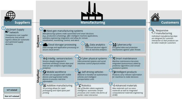
Figure 2.8 – Fifteen Components of a Factory of the Future. Adapted from (Lueth, 2015)
The Manufacturing Industry has come a long way since the creating of the
first factories to the idealization and creation of the “Smart” Factories of the F
2.3
Web Services for Industrial Internet of Things
Nowadays, due to the increasing development of the technology used in factories and in industry in general which aim to further improve the way
ro-bots and machines in industry are being more and more interconnected and op-timized, there is a branch of the Internet of Things (IoT) dedicated especially to
the industry, the Industrial Internet of Things (IIoT).
There is no clear and fully accepted definition of the Internet of Things (IoT) paradigm, even searching the literature it might be difficult to understand what IoT really means, which basic ideas stand behind this concept, and which social, economic and technical implications the full deployment of the IoT will have. The first place where ideas differ is right on the approach taken by each stakeholders, business alliances, research and standardization bodies concern-ing the Internet of Thconcern-ings, each of these start approachconcern-ing the issue from either an “Internet oriented” or a “Things oriented” perspective, depending on their specific interests, finalities and backgrounds (Atzori, Iera, Atzori, Iera, & Mo-rabito, 2010).
According to (Atzori et al., 2010), the very first definition of IoT derives from a “Things oriented” perspective; the considered things were very simple
items: Radio-Frequency IDentification (RFID) tags and the term “Internet of
2.3 Web Services for Industrial Internet of Things
Simply put, such as (Jeschke, Brecher, Meisen, Özdemir, & Eschert, 2017)
ascribes to (Atzori et al., 2010), “The Internet of Things (IoT) is an information
network of physical objects (sensors, machines, cars, buildings, and other items) that allows interaction and cooperation of these objects to reach common goals”. The Internet of things has today many applications such as transport a-tion, healthcare, smart homes and industrial environments (Whitmore,
Agarwal, & Xu, 2016). When applied to the last, it can be called “Industrial I
n-ternet of Things” (IIoT). Its main purpose is to transform the way field assets (e.g., machines or robots) connect and communicate within a factory or between factories, resorting to the use of sensors, advanced analytics, and intelligent de-cision making (Wang, Wan, Li, & Zhang, 2016). Through it sensors, machines, and Information Technology (IT) systems will be able to interact with one an-other using industrial internet technology and send constant and real-time re-ports to whom they may concern.
According to a study commissioned by Forrester Consulting, 67% of the surveyed manufactures are concerned with lack of standard interfaces and in-teroperability challenges (Forrester Consulting 2015). Some efforts are being made in order to implement the IIoT in today’s industry, starting by addressing the standardization challenges, promoting open interoperability and the wide-spread usage of a common architecture. International Electrotechnical Commis-sion (IEC), Standardization Management Board (SMB), for instance, has estab-lished in 2014 a Strategy Group, SG8, to deal with a number of tasks related to smart manufacturing, whose primary focus is to “leverage the adoption of cu r-rent and next generation technologies to achieve safe and secure factory opera-tions” (IEC.ch). The Industrial Internet Consortium (IIC) was founded with the purpose to, among other things, further improve the industry by accelerating the development, adoption, and widespread use of interconnected machines, devices, and intelligent analytics (IIC.org). Also the Institute of Electrical and Electronics Engineers (IEEE) Project P2413 and OneM2M, aim to focus on de-veloping an architecture framework for IoT and defining how devices and ser-vices are used in the IoT communication, (IEE, 2016) and (onem2m.org).
Wat-son, & Usländer, 2017) test-beds for smart production technologies (called ex-perimental factories) have been created with the purpose of establishing in-teroperability guidelines and applying new IT technologies in existing auto-mated systems, and thus demonstrate how technologies from different organi-zations can work together and support new innovations. However, still accord-ing to (Jung et al., 2017) has been no attempt to interconnect these experimental factories and allow them to flexibly adapt their production capabilities based on
cross-site demands, so a project was created by Korea Evaluation Institute of Industrial Technology (KEIT) to build a way to easily interconnect different fac-tories in order to meet all the demands (keit.re.kr).
In order to manage the usage of all these smart embedded devices in in-dustry, applications become necessary to better integrate real-time state of the physical world, and hence, provide services that are highly dynamic, more di-verse, and efficient. To incorporate these applications Service-Oriented Archi-tecture (SOA) is in order, traditionally used to couple functionality of heavy-weight corporate Information Technology (IT) systems, and besides, in such in-frastructures, composed of large numbers of networked, resource-limited de-vices, the discovery and usage of remote services is a significant challenge
(Guinard, Member, Trifa, & Member, 2010). Web Services can, therefore, be used to allow each device to offer its functionalities and, at the same time, dis-cover and invoke others functionalities offered by services of other devices dy-namically and on-demand, as suggested by (Karnouskos, Baecker, & S, 2007).
To keep the available Web Services always accessible and organized the Universal Description, Discovery and Integration (UDDI) registry is widely
used (for example the jUDDI by OASIS, https://juddi.apache.org/). The usage
of UDDI allows the Web Services to be easily found and used, and furthermore, their registration and discovery turns transparent to the Web Services provid-ers. According to (Qian, Baokang, Yunjian, Jinshu, & You, 2014), there are 3 roles in SOA: Service Provider, Service Registration Centre and Service Reques-tor, and is in the Service Registration Centre, that the Web Services are stored. There, the UDDI gives descriptive information related to the Web Services and,
2.3 Web Services for Industrial Internet of Things
Web Services can be provided through Cloud Computing, especially as Software as a Service. In Cloud Computing environment, all the computing in-frastructure resources are provided as services over the Internet, like Infrastruc-ture as a Service(IaaS), or Platform as a Service (PaaS) or Software as a Service (SaaS) (like the Web Services), etc. Also, Cloud Computing is very used in vice Oriented Architectures (SOA) which are mainly implemented by Web Ser-vices (Duan, Yan, & Vasilakos, 2012), and because computer systems leased
2.4
FIWARE
FIWARE or FI-WARE is a community founded by the European Union whose goal is to provide a middleware platform where developers can create
and deploy applications and services for the Future Internet. Once a service or application is created, they are filed in FIWARE Catalogue where anyone can
open and use them at their own free will since they all are stored in a public and royalty-free platform.
This FIWARE community is an open one, which is formed no only by the developers of the technology but by all those who contribute to materialize the FIWARE mission: “to build an open sustainable ecosystem around public, ro y-alty-free and implementation-driven software platform standards that will ease
the development of new Smart Applications in multiple sectors” (Fiware.org,
2016).
In order cover a large variety of purposes the FIWARE Community has some sub-programs besides the core FIWARE program where it provides a set of APIs (Application Programming Interfaces) like previously mentioned.
Among these sub-programs, one can find:
FIWARE Lab – where the users can test the provided technology or their
own, in some experimental infrastructures developed by the FIWARE commu-nity where entrepreneurs and domain stakeholders can meet;
FIWARE Accelerate – where interested developers are encouraged to
de-velop new bold solutions to further improve the FIWARE platform. This pro-gram focuses mainly in SMEs (Small and Medium-sized Enterprises) and start-ups.
FIWARE Mundus – Program which ambitions are to turn the Europe-size
community into a worldwide community, reaching foreign stakeholders and
2.4 FIWARE
FIWARE iHubs – as the name implies, aims to create operational Hubs
nodes in order to build communities of adopters and contributors at a local lev-el.
Further information about the FIWARE platform and community can be
found on their original website (www.fiware.org).
One of the many applications that the FIWARE platform can have is in the Smart Cities domain. Many of the developments achieved in the FIWARE community can be used to improve the concept of the Smart Cities creating smart cities applications which in time will attract enterprises and start-ups who will further innovate and provide a better city for citizens and businesses (Crouch, 2015).
In the FIWARE Catalogue is present a rich library of components, al-ready programmed, implemented and al-ready to be used and/or changed by
an-yone since they are all public royalty-free and open source, called Generic Ena-blers. There, Enablers can be found which can be used in many different con-texts such as:
➢ Internet of Things (IoT) Services Enablement;
➢ Advanced Web-based User Interface;
➢ Security;
➢ Interface to Networks and Devices (I2ND);
➢ Architecture of Applications/Services Ecosystem and Delivery
Framework;
➢ Data/Context Management;
➢ Cloud Hosting.
In the last two are included not only the Enablers used during the devel-opment of this thesis “FIWARE Orion Context Broker”, described in chapter
3.5.2 and “FIWARE Short Time Historic (STH) – Comet”, described in chapter
3.5.3, but also the program used to run these enablers, the “Docker” described
2.5
IoT as a Service
The Internet of Things presupposes the interaction between innumerable, physical world objects and their virtual counterparts, allowing these objects to
capture and send information to the Internet. Or as defined by (Lake, Rayes, &
Morrow, 2012), “the Internet of Things (IoT) consists of networks of sensors a
t-tached to objects and communications devices, providing data that can be
ana-lysed and used to initiate automated actions”. In order to integrate all these
physical objects with the digital world, there is necessary to find a way to make them accessible in the Internet, and therefore an Internet of Things as a Service approach, is necessary.
2.5.1
Model
The first step to making the “Things” from the Internet of Things, access i-ble is the creation of a model through which, the physical “things”, can be found and accessed. According to (Bauer, Martinbauerneclabeu, & Meissner,
2011), the research, so far developed, in this area has focused mainly on “sensor
descriptions and observation data modelling” that offer sensor measurement
data services on the web. The SENSEI Project (Herault & Presser, 2008), for in-stances (a project created with the intention of developing a framework of uni-versal service interfaces for Wireless Sensor and Actuator Networks (WSANs))
made use of a resource model to capture resource functionalities and discover where and how they could be accessed. It would then publish that information in a repository, where it could be accessed by specific ontologies.
In the SENSEI Project, like mentioned before, the core modelling concept is the “resource”, which implies that all sensors, actuators, processors, etc. are there modelled as resources. Let us take as an example of a model, the IoT
2.5 IoT as a Service
Figure 2.9 – IoT model: key concepts and interactions. Adapted from(Bauer et al., 2011)
In Figure 2.9, it is easy to see how an Entity, which has a Device attached,
here associated with a Resource (a norm taken by the SENSEI Project), can be accessed through a service provided in the Internet.
2.5.2
Framework
Step two, in the Internet of Things as a Service paradigm is the creation
and usage of a Framework. In order to make the paradigm accessible to every-one, no matter if they are a big industry or a small anonymous people, and to make sure all will benefit from it, an open service framework needs to be creat-ed. Once this open service framework is created and available to everyone it can bring many advantages to everyone’s lives, service providers, device develo p-ers, software developp-ers, consump-ers, etc.
According to (Kim & Lee, 2014), even though there have already been made some IoT Frameworks, those were mainly created by big enterprises such as governments or companies and are mostly based on B2B (Business to Busi-ness) and B2G (Business to Government) business models. However, there are also open service platforms for IoT, of which the best-known example is Cosm, former Pachube, and recently purchased by cloud computing service provider
securely store and exchange data. Through Web–based registration service it allowed users to control, monitor, and analyse data collected from IoT devices, besides giving them a way to search and find those devices (Kim & Lee, 2014). Another open service framework currently deployed is EVRYTHNG that, as described by (Kim & Lee, 2014), grants every physical thing an Active Digital Identity (ADI), and provides to the device and software developers, all the nec-essary tools to create new services and applications to the everyday items and
devices (EVRYTHNG, n.d.).
In (Kim & Lee, 2014), an open service framework for IoT is presented where a developer-oriented structure is used to encourage developers to create and make available App/Web Software and services to the users. On the users side a quick search for IoT services and devices is offered, and when they in-tend to connect to the searched IoT device, the software related to that device is downloaded to their smartphone or tablet or etc. and its provided service is made available. The architecture used in this open service framework is depict-ed in Figure 2.10.
2.5 IoT as a Service
At the framework presented in Figure 2.10, an open API (Application
Pro-gramming Interface) is used, as well as a Planet Platform (described as “a server
platform for IoT device registration, management, monitoring, and search in the global IoT environment”), a Device Platform (software platform “to help connecting and cooperating things to Open IoT platforms and application soft-ware”), a Store Platform (“App/Web store containing applications or links to Web address that provide user services through interaction between IoT
devic-es or Mashup Platforms”) and finally a Mashup Platform (“service platform for
providing new integrated services based on data sets collected from IoT devices
and its mashup of information over the Internet”) (Kim & Lee, 2014).
2.5.3
Mashup
Also needed to allow further development of the IoT model or framework is a Mashup. The idea behind a “Mashup” is to create new content by reusing or recombining previous existing content from various sources thus allowing people who do not master all programming languages to easily build new Web Applications, or others, by providing some easy-to-use functionalities. A Mashup is, therefore, a way to compose a new service from existing services and, “when applied directly to the Web domain, a Mashup is a Web-based ap-plication that is created by combining and processing on-line third party re-sources that contribute with data, presentation or functionality” (Koschmider, Torres, & Pelechano, 2009).
Unlike regular Web Services that are provided in a specific domain and available at any time in the web, IoT devices, providing a service, are not al-ways available and not alal-ways working in the same place. In addition, it is also
where an IoTMaaS (IoT Mashup as a Service) is introduced.
According to (Im et al., 2013), IoTMaaS is defined as “a mashup of things,
software, and computation resource”, and is presented as a cloud-based IoT mashup service model. In IoTMaaS, thing is described as “any identifiable o
b-ject which can have sensing and actuation services; software is an “assembly
description of software components”; and computation resource is “a current computer model consisting of CPU, memory, disk, persistent storage, network,
etc. How these components interact with the IoT world is depicted in Figure 2.11.
Figure 2.11 – IoTMaaS (IoT Mashup as a Service) concept. Adapted from(Im et al., 2013)
2.6 From the State of the Art to this Thesis concept
2.6
From the State of the Art to this Thesis concept
As stated in this thesis’ State of the Art, the kernel is the central part of a
computer operating system and serves, among many other things, as a bridge
between hardware devices and the software applications accessing those devic-es, whether they are I/O devicdevic-es, plugged devices or IoT devices. The applica-tions developed during this thesis’ elaboration will make use of IoT devices and the services provided by them to offer contributions to the users and to the vf-OS project itself. Therefore it is important to understand the how the interaction between those devices and the vf-OS Manufacturing Operating System will happen, and that interaction happens through the system kernel.
Both the vf-OS project and this thesis’ scenario in particular, purpose is to
provide some contributions to the development of the factories of the future. Even though this thesis’ applications were developed primarily to the agricul-ture scenario, with minor changes they can be used at any other strand includ-ed in the Factories of the Future paradigm.
In order to apply the perks of the IoT to this Factories of the Future world,
there are many ways to interconnect the physical world objects and the soft-ware systems through a service oriented approach. Some ways are presented in this thesis’ State of the Art, such as the usage of Web Services to offer online, the services provided by a certain IoT device. In addition to the Web Services, an-other approach to create an IoT service oriented system, is the usage of cloud computing to allow the IoT devices functions to be made available online. Some Generic Enablers provided by the European FIWARE make use of a cloud com-puting system to make available online the functions provided by IoT sensors.
After briefly going through all these essential aspects, the environment under which this thesis is developed is fully contextualized (the Kernel where
the vf-OS that includes this thesis’ project aims to provide solutions, the
Facto-ries of the Future where this project is to be applied, Web Services for Industrial
Internet of Things as an alternative way to implement the IoT Service Oriented System, the FIWARE which provides the technology used during this project
development and the IoT as a Service which is the main focus of this thesis’
2.7
Research Question and Hypothesis
This master thesis project aims to show and provide a way to encompass physical objects working under an IoT approach to be used in a Service
Orient-ed System. In order words, this thesis intends to show a way of how it is possi-ble make availapossi-ble online, the services and functions provided by IoT devices,
or as its title states, present a Framework for IoT Service Oriented Systems.
In order to further clarify the goal of his master thesis project a Research Question and a Hypothesis were created with the help of the UNINOVA devel-opers of the vf-OS Project.
After analysing what was already available in the market and which were the vf-OS needs, the Research Question found to guide the thesis development according to the market and he vf-OS needs was:
“How can a framework provide guidance to make IoT services discovered
for effective use?”
To answer this question, and once again to guide the thesis development and answer the market and the vf-OS needs, a Hypothesis was generated. The produced Hypothesis intends to cover not only the thesis main objective, which is the implementation of an IoT service oriented system, but also the technology used for this purpose and its advantages for this goal. Thus, the produced Hy-pothesis was:
“If the FIWARE technology can provide modularity and discovery
solu-tions then integrate IoT devices through generic enablers will facilitate IoT
3
Practical Framework
In this chapter, is presented the practical framework under which this master thesis is developed. This master thesis is developed under the European vf-OS Project and is supervised by the UNINOVA institute. The main goal of this thesis is to provide small contributions to the vf-OS Project, explained in this chapter. In order to provide such contributions, the Use Case Scenarios pre-sented in the projected were addressed and a real-life scenario was created. Combining the created scenario and the generic Use Case Scenarios, five inter-connected applications were developed in order to provide answers to both the Use Case Scenarios and the practical scenario at the same time.
In addition to the project which holds this master thesis development, the Use Case Scenarios addressed and real-life scenario created, also the
technolo-gies used to develop the applications are presented in this chapter. Among the used technologies are the FIWARE Generic Enablers. The usage of these open source European technologies allows the vf-OS components, and therefore these thesis’ applications, to become as generic and standard as possible allow-ing them to be used by anyone regardless of the FoF field on which they are us-ing them, factories, manufacture, agriculture, etc.
3
CHAPT
3.1
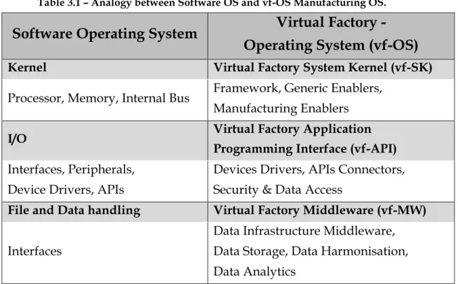
vf-OS (virtual factory - Operating System)
Like previously mentioned, the European vf-OS Project aims to be an Open Virtual Factories Operating System, including a Virtual Factory System
Kernel (vf-SK), a Virtual Factory Application Programming Interface (vf-API) and a Virtual Factory Middleware (vf-MW) specifically designed for the
facto-ries of the future. This Open Framework will be able to manage the overall network of a collaborative manufacturing and logistics environment, and there-fore enable humans, applications and devices to communicate and interoperate in the interconnected operative environment. Plus, the vf-OS will provide a set of Open Services, rooted in the cloud and instantiated at the vf-OS Platform, moving the industry from the device-centric to the user-centric paradigm. This Open Platform is to be linked by strong and advanced ICT (like CPS, IoT Cloud-Models, M2M, etc.) in order to fulfil the actual need on the market for open services interoperability based on data exchange. When it comes to hard-ware functions, the OS will act as an intermediary between the applications be-haviours of the factory and the factory hardware itself. This will enable the
ap-plication factory functionalities and services to be virtualized and executed, ei-ther directly by the hardware eiei-ther through system calls to the OS.
The vf-OS, deployed in a cloud platform provide a range of services to the connected factory of the future to integrate better manufacturing and logistics processes. In order to do so, the vf-OS intends to not only create new technolo-gies but also greatly re-use existing tools (especially Open Source ones) and technologies (especially standardised ones). Like a regular OS, the vf-OS com-prehends core functionalities, but mainly focused in a manufacturing environ-ment. An analogy between some components of a regular Software OS and the vf-OS Manufacturing OS is presented in Table 3.1 (adapted from the vf-OS