Faculdade de Engenharia da Universidade do Porto
Arquitecturas de Hardware para um Veículo
Eléctrico
André Manuel Paiva e Rocha
Dissertação realizada no âmbito do
Mestrado Integrado em Engenharia Electrotécnica e de Computadores
Major Automação
Orientador: Prof. Doutor Paulo Portugal
i
Resumo
A indústria automóvel tem vindo ao longo dos anos a sofrer uma evolução exponencial. Os veículos modernos estão cada vez mais a ser dotados de funcionalidades que providenciam uma maior segurança, conforto, eficiência e performance. Estas funcionalidades são baseadas não só em sistemas computacionais isolados, mas resultam também da interacção entre vários sistemas, que são suportados por várias redes de comunicação de dados com requisitos e aplicações distintas.
À medida que os componentes mecânicos têm vindo a ser substituidos por equivalentes electrónicos, são exigidos a estes níveis de confiança elevados no seu funcionamento, que podem apenas ser atingidos com o recurso a técnicas de concepção de arquitecturas tolerantes a falhas.
Este trabalho apresenta uma visão geral de várias funcionalidades que podem ser encontradas nos veículos modernos, das arquitecturas e redes de comunicação que suportam o seu funcionamento, e de algumas das técnicas de concepção que permitem aumentar a confiança que pode ser depositada no funcionamento destes sistemas. Por fim, é apresentada uma proposta para uma arquitectura de um sistema de travagem com requisitos de segurança crítica.
iii
Abstract
The automotive industry has been evolving over the years in an exponential fashion. Modern vehicles are increasingly being provided with features which provide greater security, comfort, safety and performance. These features are not only based in isolated computational systems, but also result from the interaction between various systems, which are supported by several data communication networks with distinct requirements and applications.
As mechanical components are being replaced by their equivalent electronic, higher levels of dependability are being demanded from these, which can only be attained by means of fault tolerant design techniques.
This work presents an overview of the various features that can be found on modern vehicles, the architectures and communication networks that support their operation, and some of the design techniques which allow an increase of their dependability. Finally, a proposal for the architecture of a braking system with safety critical requirements is presented.
v
Agradecimentos
Aos meus pais por me terem feito acreditar que o caminho mais difícil é o que mais compensa, e por me terem dado todas as condições e mais algumas para que tivesse sucesso.
Ao Prof. Doutor Paulo Portugal, não só pelo seu profissionalismo, mas também pela sua capacidade de motivação, indispensável nos momentos mais complicados deste trabalho.
À Joana, por todo o apoio que me deu e por continuar comigo após esta longa ausência. A todos os meus amigos que de algum modo procuraram ajudar.
vii
"All the so called secrets of success will not work unless you do" Unknown Author
ix
Contents
Resumo ... i
Abstract ...iii
Agradecimentos ...v
Contents ... ix
List of Figures ... xiii
List of Tables ... xvii
Symbols and Acronyms... xix
Chapter 1 ... 1
Introduction ... 1 1.1 Motivation ... 1 1.2 Objectives ... 2 1.3 Document Structure ... 2Chapter 2 ... 5
In-Vehicle systems ... 5 2.1 Introduction ... 5 2.2 Automotive Systems ... 5 2.2.1 Powertrain ... 5 2.2.2 Chassis ... 6 2.2.3 Body ... 6 2.2.4 Passive Safety ... 7 2.2.5 Human-Machine-Interfaces (HMI) ... 72.2.6 Infotainment and Telematics ... 7
2.3 Braking Systems ... 8
2.3.1 Antilock Braking System (ABS) ... 8
2.3.2 Traction Control System (TCS) ... 14
2.3.3 Electronic Stability Control (ESC) ... 15
2.3.4 Electronic Brake Force Distribution (EBD) ... 19
2.3.5 Electronic Brake Assist (EBA) ... 20
2.3.6 Architecture of Braking ECUs ... 21
2.4 Instrument Panels ... 21
2.4.1 Information to Display ... 21
x
2.5 Steering Systems ... 25
2.5.1 Hydraulic Power Steering ... 26
2.5.2 Hybrid and Electric Power Steering ... 27
2.5.3 Power Steering Architecture ... 29
2.5.4 Four Wheel Steering (4WS) ... 30
2.6 Exterior Lighting Systems ... 32
2.6.1 Automatic Lighting ... 33
2.6.2 Fused Light Detection ... 33
2.6.3 Dynamic Headlight Range Adjustment ... 33
2.6.4 Adaptive Cornering Light ... 35
2.6.5 Camera Based Lighting Systems ... 36
2.6.6 Lighting Systems Architecture ... 39
2.7 Propulsion System ... 40
2.7.1 Regenerative Braking ... 40
2.7.2 Cruise Control ... 41
2.8 Adaptive Cruise Control (ACC) ... 41
Chapter 3 ... 43
In-Vehicle Networks ... 43
3.1 Introduction ... 43
3.2 Network Requirements for the Different Automotive Domains ... 44
3.3 In-vehicle Network Classifications ... 45
3.3.1 Class A Networks ... 45
3.3.2 Class B Networks ... 45
3.3.3 Class C Networks ... 45
3.3.4 Class D Networks ... 45
3.4 Communication Networks for the Automotive Industry... 46
3.5 Controller Area Network ... 47
3.5.1 CAN Nodes Interaction Model ... 48
3.5.2 Bus Access ... 48
3.5.3 CAN Frames ... 49
3.5.4 Overload Frames ... 52
3.5.5 Error Detection, Processing and Management ... 52
3.5.6 Fault Confinement Strategy ... 53
3.6 Flexray ... 54
3.6.1 Bus Access ... 55
3.6.2 Static Segment ... 56
3.6.3 Dynamic Segment ... 57
3.6.4 Symbol Window ... 57
3.6.5 Network Idle Time ... 57
3.6.6 Flexray Frame ... 58
3.6.7 Error Processing, Management and Transmission Security ... 59
3.7 Local Interconnect Network (LIN) ... 60
3.7.1 LIN Frames... 61
3.7.2 BUS Access ... 62
3.7.3 Error Processing and Management ... 64
3.8 Time Triggered Ethernet (TTEthernet) ... 64
3.8.1 Operational Principles and Architectures ... 65
3.8.2 Types of Messages ... 66
3.8.3 Reliability and Fault Tolerance ... 66
Chapter 4 ... 69
Drive-by-wire systems and guidelines for fault tolerant hardware design ... 69
4.1 Motivation for this Chapter ... 69
4.2 Introduction to Drive-by-wire Systems ... 69
4.2.1 Obstacles on the Implementation of Drive-by-wire Systems ... 72
xi
4.3.1 Brake-by-wire ... 72
4.3.2 Steer-by-wire ... 74
4.4 Fault Tolerant Hardware Architectures Design ... 74
4.4.1 X-by-wire Requirements for the Automotive Industry ... 76
4.4.2 Increasing Dependability ... 77
4.5 Fail Safe Units ... 81
4.5.1 Master/checker Approach ... 82
4.5.2 Duplication with Comparison ... 82
4.6 Hardware for Safety Critical Systems ... 82
4.6.1 Integrated Voltage Regulators ... 82
4.6.2 Voltage Monitors ... 82
4.6.3 Memory Protection Unit (MPU) ... 82
4.6.4 Error Correction Code Protected memories (ECC) ... 83
4.6.5 Clock Monitoring Units ... 83
4.6.6 Peripheral Components Replication... 83
4.6.7 Watchdog Timers ... 83
4.6.8 Dual Core Microcontrollers for Safety Applications ... 83
Chapter 5 ... 85
Architecture Definition ... 85
5.1 High Level Architecture ... 86
5.1.1 Architecture Limitations ... 87
5.1.2 Data Exchange between ECUs ... 87
5.1.3 ECU Services ... 88
5.2 Braking System Architecture... 90
5.2.1 Braking Architecture Network Proposal ... 93
5.2.2 Gateway... 93
5.2.3 Brake Pedal Position Module ... 95
5.2.4 Wheel Speed Acquisition Module ... 100
5.2.5 ABS, TCS and ESC Modules ... 102
5.2.6 Braking Actuator Modules ... 104
5.2.7 Power Supplies ... 107
5.2.8 Braking System Fault Analysis ... 109
Chapter 6 ... 113
Conclusions and Future Work ... 113
6.1 Conclusions ... 113
6.2 Future Work ... 114
xiii
List of Figures
Figure 1.1 - Tesla roadster, a fully electric sports vehicle ... 1
Figure 2.1 - Relationship between the adhesion coefficient and wheel slip in different road conditions [10]. ... 9
Figure 2.2 - Relationship between brake slip, lateral force coefficient, and coefficient of friction [11] ... 9
Figure 2.3 - ABS preventing wheel lock-up ... 10
Figure 2.4 - Symbolic Nomenclature ... 10
Figure 2.5 - One channel ABS ... 11
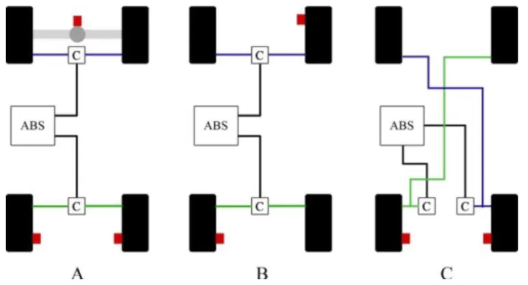
Figure 2.6 - Different arrangements for two channel ABS systems. Front wheels facing down ... 11
Figure 2.7 - Three channel ABS configuration ... 12
Figure 2.8 - Four channel ABS system ... 12
Figure 2.9 - Architecture of the Antilock Braking System ... 13
Figure 2.10 - Architecture of the Antilock Braking System with an ASIC for sensor processing and distribution ... 13
Figure 2.11 - Vehicle in a split friction coefficient surface ... 14
Figure 2.12 - Duality between ABS and TCS [11]. ... 15
Figure 2.13 - Vehicle side slip angle ... 16
Figure 2.14 - Relationship between the yaw moment and the side slip angle [11] ... 16
Figure 2.15 - Vehicle experiencing under and over steering ... 17
Figure 2.16 - ESC operation during over steering ... 18
Figure 2.17 - ESC operation during understeering ... 18
xiv
Figure 2.19 - EBD applying more brake force at the front wheels in a front engine car ... 20
Figure 2.20 - EBA actuation ... 20
Figure 2.21 - Instrument panel point-to-point architecture example ... 23
Figure 2.22 - Instrument panel networked architecture example ... 24
Figure 2.23 - Hydraulic power steering system applied to a rack-and-pinion configuration [20] ... 26
Figure 2.24 - Power steering hydraulic pump [20] ... 27
Figure 2.25 - Power steering assist curve [22]... 28
Figure 2.26 - Electric power steering [24] ... 29
Figure 2.27 - Power steering architecture ... 29
Figure 2.28 : Ackerman drive geometry ... 30
Figure 2.29 : 4WD decrease of turning radius ... 30
Figure 2.30 - 4WD at high speeds ... 31
Figure 2.31 - Increased stability of the 4WS system when compared to 2WS [28] ... 31
Figure 2.32 - 4WS Jeep Hurricane [29] ... 31
Figure 2.33 - 4WS architecture ... 32
Figure 2.34 - Vehicle with headlights on ... 34
Figure 2.35 - Range of headlights increased due to forward tilt ... 34
Figure 2.36 - Dynamic headlights range adjustment maintaining headlight range despite of vehicle tilt ... 34
Figure 2.37 - Dynamic Headlight Range Adjustment Architecture ... 35
Figure 2.38 - Vehicle without adaptive cornering light system ... 35
Figure 2.39 - Vehicle equipped with adaptive light cornering system ... 36
Figure 2.40 - Adaptive cutoff line ... 37
Figure 2.41 - Glare free system ... 37
Figure 2.42 - Marking light system evidencing a pedestrian ... 38
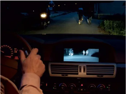
Figure 2.43 - BMW night vision system ... 39
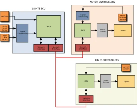
Figure 2.44 - Lighting systems' architecture ... 39
Figure 2.45 - Propulsion system architecture ... 40
xv
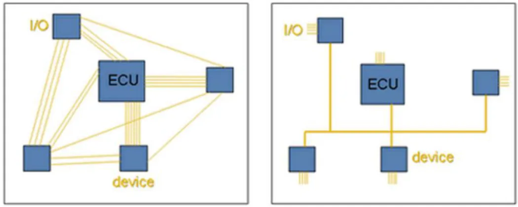
Figure 3.1 - Reduction of number of wiring by means of interconnecting ECUs in a network . 43
Figure 3.2 - CAN arbitration procedure in a wired-and bus [38] ... 48
Figure 3.3 - CAN data frame [40] ... 49
Figure 3.4 - Standard format of CAN frame arbitration and control fields [40] ... 50
Figure 3.5 - Extended format of CAN arbitration and control fields [40] ... 50
Figure 3.6 - CAN error frame structure [40] ... 52
Figure 3.7 - Transitions between error states in CAN ... 54
Figure 3.8 - Flexray topologies [42] ... 55
Figure 3.9 - Flexray communication cycle ... 55
Figure 3.10 - Flexray static segment ... 56
Figure 3.11 - Flexray in-cycle control ... 56
Figure 3.12 - Minislots in the dynamic segment ... 57
Figure 3.13 - Minislot expansion ... 57
Figure 3.14 - Flexray frame [42] ... 58
Figure 3.15 - Message delay in a two channel Flexray network ... 60
Figure 3.16 - LIN as a sub-bus of CAN [38] ... 61
Figure 3.17 - LIN frame [44] ... 61
Figure 3.18 - LIN bus access [44] ... 63
Figure 3.19 - Unconditional frames transfer [44] ... 63
Figure 3.20 - Event triggered frames transfer [44] ... 64
Figure 3.21 - TTEthernet redundant architecture [45] ... 65
Figure 3.22 - TTEthernet multiple redundant channels [45] ... 67
Figure 4.1 - Citroen C5 by wire: acceleration and braking integrated in the steering wheel [48] ... 70
Figure 4.2 - General Motors Hy-wire concept car [49] ... 70
Figure 4.3 - Fault tolerant architecture [50] ... 71
Figure 4.4 - ETC mechanism in internal combustion engines [52] ... 71
Figure 4.5 - Electro hydraulic brakes scheme [50] ... 73
Figure 4.6 - Electro mechanical brake-by-wire [50] ... 73
xvi
Figure 4.8 - N modular redundancy ... 78
Figure 4.9 - Static redundancy applied to steer-by-wire ... 78
Figure 4.10 - Standby spare architecture concept ... 79
Figure 4.11 - Standby sparing applied to steering actuators ... 80
Figure 4.12 - Standby sparing applied to brake-by-wire ... 80
Figure 4.13 - Pair and spare architecture ... 81
Figure 4.14 - Pair and spare architecture applied to brake-by-wire ... 81
Figure 4.15 - MPC5643L block diagram [63] ... 84
Figure 5.1 - High level view of the proposed architecture ... 86
Figure 5.2 - Braking system architecture ... 92
Figure 5.3 - Gateway ... 94
Figure 5.4 -Time frame of messages delivered to the main element ... 95
Figure 5.5 - Brake pedal position module ... 96
Figure 5.6 - Unsynchronized units ... 96
Figure 5.7 - Synchronism diagram ... 97
Figure 5.8 - Synchronism algorithm ... 97
Figure 5.9 - Brake pedal depression dynamics ... 98
Figure 5.10 - Fault detection by observation of a plausible brake pedal depression ... 99
Figure 5.11 - Brake pedal position module algorithm ... 99
Figure 5.12 - Wheel speed acquisition module ... 100
Figure 5.13 - Algorithm for ensuring fail safe behavior of wheel speed acquisition modules. 101 Figure 5.14 - Algorithm for achieving fail safe operation applicable to the ABS, ESC and TCS systems ... 103
Figure 5.15 - Erroneous operation of the brake actuator ... 104
Figure 5.16 - Detailed view of brake actuator module connections ... 105
Figure 5.17 - Algorithm which ensures the fail safe of brake actuator elements ... 106
Figure 5.18 - Algorithm which checks if actuator behavior corresponds to desired behavior 107 Figure 5.19 - Different responses from the vehicle according to different configurations of power supplies upon power outage ... 108
xvii
List of Tables
Table 3.1 - Automotive domains and their major requirements. Based in [7] ... 44
Table 3.2 - CAN standards ... 47
Table 4.1 - Risk classification according to IEC 61508... 75
Table 4.2 - Interpretation of the various risk levels according to IEC 61508 ... 75
Table 4.3 - IEC 61508 safety integrity levels for continuous mode of operation ... 75
Table 4.4 - IEC 61508 safety integrity levels for on demand mode of operation ... 76
Table 5.1 - Motor variables of interest ... 87
Table 5.2- Lights ECU variables of interest ... 87
Table 5.3 - Brake ECU variables of interest ... 88
Table 5.4 - Steering ECU variables of interest ... 88
Table 5.5 - Output of the main element according to incoming messages ... 95
Table 5.6 - Gateway fault analysis ... 109
Table 5.7 - Network channels fault analysis ... 109
Table 5.8 - Brake pedal position fault analysis ... 110
Table 5.9 - ABS, TCS and ESC modules fault analysis ... 110
Table 5.10 - Brake actuator modules fault analysis ... 110
Table 5.11 - Wheel speed acquisition module fault analysis ... 111
xix
Symbols and Acronyms
4WS - Four Wheel Steering ABS – Antilock Braking System ACC - Adaptive Cruise Control
ASIC - Application Specific Integrated Circuit CAN - Controller Area Network
CRC - Cyclic Redundancy Check
CSMA/CD - Carrier Sense Multiple Access with Collision Detection DEEC - Departamento de Engenharia Electrotécnica e Computadores EBA - Electronic Brake Assist
EBD - Electronic Brake Force Distribution ECU - Electronic Control Unit
EHB - Electro Hydraulic Brake EMB - Electro Mechanical Brake ESC - Electronic Stability Control ETA - Event Tree Analysis ETC - Electronic Throttle Control EV - Electric Vehicle
FEUP - Faculdade de Engenharia da Universidade do Porto FMEA - Failure Modes and Effects Analysis
FSU - Fail Silent Unit FTA - Fault Tree Analysis FTU - Fault Tolerant Unit HCU - Hydraulic Control Unit LED - Light Emitting Diode LIN - Local Interconnect Network LSB - Least Significant Bit MCU - Microcontroller Unit
MOST - Media Oriented Systems Transport MSB - Most Significant Bit
RPM - Revolutions Per Minute
TDMA - Time Division Multiple Access TTEthernet - Time Triggered Ethernet
1
Chapter 1
Introduction
1.1 Motivation
Recent environmental concerns allied to a decrease in the available sources of fossil fuel are leading vehicle manufacturers to invest on the development of alternative transportation methods. The use of electrical energy on vehicles is promising, since it can be obtained in a more efficient way with a lower impact on the environment [1].
Even when the energy which supplies electric vehicles (EVs) is obtained by means of polluting fuel sources such as coal, crude or oil, the efficiency provided by electric vehicle powertrains results in cleaner ecological footprints when comparing to internal combustion engine (ICE) vehicles [2, 3]. The future is even brighter, as efforts are widely being put together to convert carbon emitting power stations into clean renewable sources of energy, motivated by European Union targets of having at least 20% of the energy consumed coming from renewable resources until the year of 2020 [4].
It has been demonstrated that the acceleration, speed and handling of electric vehicles can equal or exceed that of ICE vehicles [5]. Moreover, electric vehicles produce less noise and emit zero tailpipe gases, making them the appropriate choice for use in urban transportation.
2 Introduction
The department of electrical and computer engineering (DEEC) at the Faculty of Engineering of the University of Porto (FEUP) has just finished building a new laboratory which will host the development of many projects related with EVs. This new infrastructure will allow students to develop solutions related to EVs along their academic career.
Several features which provide greater safety, comfort, efficiency and performance, are being increasingly integrated in modern vehicles. The information about such features, their hardware architectures, the communication networks that support their operation, and the techniques used by manufacturers to provide them with the required dependability levels, is significantly widespread.
The agglomeration of such information on a single document will allow students to easily move for the actual implementation of these features.
1.2 Objectives
Two main objectives have been defined for this thesis. The first objective is the elaboration of a survey covering:
The various features that are commonly found on modern vehicles, their general concepts of operation, and the hardware architectures which support their behavior
The networking solutions used in the automotive industry which support the behavior of the identified features
The second objective of this work is the proposal of a conceptual architecture for the braking system whose implementation can be achieved taking in consideration:
The background obtained by students along their academic career The feasibility of the braking system by the students
The availability and cost of the components that will support the proposed architecture
The aspects of dependability in which a braking system much rely on
1.3 Document Structure
This document is divided into 6 chapters.
Chapter 1 presents the motivation behind this work and the objectives that have been
defined.
Chapter 2 provides an overview on the systems that are commonly found in modern vehicles,
their major requirements, and a closer look on the systems which are considered to be a priority for the development of projects within the context of the new automotive laboratory.
Chapter 3 addresses the networking solutions which are used to interconnect the systems
referred in Chapter 2. Controller area network (CAN), local interconnect network (LIN) and Flexray are presented due to their actual importance in the automotive industry. TTEthernet is presented as a promising solution for future vehicles.
Document Structure 3
Chapter 4 presents the emerging concept of by-wire systems applied to the automotive
industry. Several techniques and ideas that can be used by students to increase the dependability of their systems are introduced in this chapter.
Chapter 5 presents the proposed hardware architecture for the braking system architecture
and the algorithms which support its dependability.
5
Chapter 2
In-Vehicle systems
2.1 Introduction
The first part of this chapter starts with an overview of the different systems that can be usually found on vehicles. Afterwards, several of these systems which are considered to be a priority for the development of the EV project are explored with further detail.
2.2 Automotive Systems
The various subsystems that compose a vehicle can be classified into several domains according to their functionalities. The number and name of these domains varies along the literature [6, 7]. In this section, seven domains are considered and an overview of typical systems and requirements is presented.
2.2.1 Powertrain
The powertrain enclosures the systems that are responsible for converting power into the motion of the vehicle. Examples of systems in the powertrain domain are
the propulsion system controller which has the task of controlling the propulsion device (which can be an electric motor or an internal combustion engine) according to the driver's inputs and requests from other systems, such as the electronic stability control, traction control system or adaptive cruise control. automatic transmission controllers
battery management systems
Systems belonging to this domain are characterized by:
High computational power to deal with the complex algorithms that support the control of the propulsion and transmission devices
6 In-Vehicle systems
Hard real-time requirements
2.2.2 Chassis
The chassis domain integrates the systems responsible for the interaction between the vehicle and the road [6]. This domain includes braking, steering and suspension systems. Examples of systems in the chassis domain are
Power steering which monitors the driver's steering intentions and provides an assisting force in steering the vehicle
Antilock braking system (ABS) for wheel lock-up prevention upon braking Electronic Stability Control (ESC) to prevent the vehicle from skidding
Traction Control System (TSC) in order to control vehicle traction when accelerating
Adaptive Cruise Control (ACC) to enhance comfort by the autonomous control of the distance or headway time to front vehicles
Electronic Damper Control (EDC) to control the vertical movement of the wheels
Systems which belong to this domain are characterized by having:
High computational power High sampling/actuation rates Hard real-time requirements
Fail safe constraints which allow these systems to fail in a safe way Fault tolerance in the case of x-by-wire and steer-by-wire systems
2.2.3 Body
The body domain comprises systems that do not interfere with the vehicle dynamics. Examples of systems belonging to the body domain are
interior and exterior lighting systems
air conditioning systems which control the temperature of the cockpit
vehicle access systems which ease the access to the vehicle and provide security seat control systems which provide more comfort
park distance control which monitors the distance to obstacles to aid the driver when parking the vehicle
Systems belonging to this domain are typically characterized by having:
Low computational power
Low sampling/actuation rates as events are mostly triggered by human interaction Soft real-time requirements
It must be noted, however, that lighting systems are evolving in a way in which they do not share the computational requirements with other systems from the body domain. Several lighting systems whose requirements are most approximated with the powertrain and chassis requirements are presented in Section 2.6.
Automotive Systems 7
2.2.4 Passive Safety
Passive safety systems operate in order to reduce the effects of a crash. Examples of systems belonging to this domain are:
Airbag systems which deploy inflatable envelops upon impact according to the type (front impact, lateral impact) and severity of impact, with the intention of reducing shocks applied to the driver
Seat belt pretensioners which maintain the driver in a steady position during crashes and sudden vehicle movements
Systems belonging to this domain are typically characterized by having:
High computational power High sampling/actuation rates Hard real-time requirements Fail safe constraints
2.2.5 Human-Machine-Interfaces (HMI)
HMI systems provide the interaction between the driver and the vehicle. Examples of systems belonging to this domain are:
Instrument panels which provide information on the status of many of the vehicle variables of interest such as speed, rpm, fuel level among others
Tire pressure management systems which monitor tire pressure and informs the driver of possible dangerous situations
Systems belonging to this domain are typically characterized by having:
Low to high computational power depending on the complexity of the display systems
Medium sampling/actuation times, congruent with human perception Soft real time requirements
2.2.6 Infotainment and Telematics
Infotainment and telematics systems provide information, entertainment and the interaction between the vehicle and the exterior world. Examples of systems belonging to this domain are:
Global positioning systems that provide the driver with information on its location, direction and speed
Audio Systems DVD Players
Fleet management systems which allows the tracking of vehicles Vehicle internet connection
8 In-Vehicle systems
Systems belonging to this domain are typically characterized by having:
Very high computational power Soft real-time requirements
2.3 Braking Systems
This section presents an overview of the features and architectures of braking systems. Braking systems are safety critical on their nature. This means that the failure of these systems to perform their expected operations can result in a catastrophic event, such as the damage of the vehicle and ultimately the injury or dead of people and environmental harm. The architectures of braking systems are therefore conceived taking in consideration the required dependability for their operation. Throughout this section, these systems are presented without the consideration of these issues as general references for the development of safety critical systems are given Chapter 4.
The architectures presented in this chapter may reflect slight adaptations from the studied systems. Therefore, several details that do not contribute for the understanding or the concepts involved were omitted.
2.3.1 Antilock Braking System (ABS)
According to [8], the ABS system reduces fatal collisions with pedestrians in thirteen percent and achieves a twelve percent reduction in collisions between vehicles on wet roads. The ABS was proven to grant more efficiency in nonfatal crashes, reducing the overall crash rate by six percent for passenger cars and eight percent for light trucks and vans.
The ABS is a safety-related feature that assists the driver in deceleration of the vehicle in poor or marginal braking conditions, such as wet, icy or sandy pavements [9].
When the driver presses the brake pedal, a force is generated on the wheels which counteracts its motion. Depending on the surface in which the wheels are spinning, this braking force can achieve a value that can cause the wheels to slip.
The relationship between the vehicle speed and the slip of the wheel is denominated brake slip and is defined as the ratio between the speed of the wheel and the speed of the vehicle itself 𝜆 =𝑆𝑣𝑒𝑖𝑐𝑙𝑒− 𝑆𝑤𝑒𝑒𝑙 𝑆𝑣𝑒𝑖𝑐𝑙𝑒 × 100% 𝑤𝑒𝑟𝑒: 𝜆: 𝑏𝑟𝑎𝑘𝑒 𝑠𝑙𝑖𝑝 𝑆𝑣𝑒𝑖𝑐𝑙𝑒: 𝑠𝑝𝑒𝑒𝑑 𝑜𝑓 𝑡𝑒 𝑣𝑒𝑖𝑐𝑙𝑒 (𝑚𝑒𝑡𝑒𝑟𝑠/𝑠𝑒𝑐𝑜𝑛𝑑) 𝑆𝑤𝑒𝑒𝑙: 𝑠𝑝𝑒𝑒𝑑 𝑜𝑓 𝑡𝑒 𝑤𝑒𝑒𝑙 (𝑚𝑒𝑡𝑒𝑟𝑠/𝑠𝑒𝑐𝑜𝑛𝑑) (2.1)
Figure 2.1 illustrates the relationship between the wheel slip and the adhesion coefficient of the wheels for several surfaces. The higher the adhesion coefficient is, the more braking force is effectively used to reduce vehicle speed and consequently its stopping distance.
Braking Systems 9
Disregarding snowy surfaces, it can be denoted that the adhesion coefficient reaches its maximum value, and after decreases with the increase of wheel slip. It can be concluded that the higher the wheel slip is, the higher the stopping distance of a vehicle will be.
Figure 2.1 - Relationship between the adhesion coefficient and wheel slip in different road conditions [10].
The lateral friction is what enables the vehicle to steer [10]. Its value is also dependent on wheel slip, as illustrated by Figure 2.2. It can be seen that as the wheel slip ratio increases, the lateral friction coefficient decreases and so the vehicle maneuverability.
The chart on Figure 2.2 depicts two distinct zones in respect to wheel slip: the stable and the unstable zone. The stable zone ends where the maximum value of the friction coefficient is reached. The unstable zone is characterized by a rapid deceleration of wheel speed, that leads to wheel lock-up, corresponding to the minimum lateral friction coefficient. At this point, wheels are completely blocked and the vehicle maneuverability is drastically reduced.
10 In-Vehicle systems
2.3.1.1 ABS Operation
The objective of the ABS system is to ensure that the brakes operate near their most efficient point, therefore granting steering control at all times and shorter stopping distances [12]. This is achieved by controlling wheel slip so that its value is kept below the unstable zone. Wheel slip is controlled by controlling the force applied to the brakes.
The ABS constantly monitors wheel speed for situations that might indicate wheel slip approaching the unstable zone. If such situation is detected, the brake force applied is prevented to be raised any further. In case that the wheel slip steps into the unstable zone, the ABS reduces brake force so wheel slip is taken back into the stable zone. To avoid under braking and maximize braking efficiency, the brake force is then increased and the process repeats itself.
An example of the braking force modeled by the ABS against the braking force that would be applied without ABS is illustrated on Figure 2.3. In red it can be seen the driver’s braking intension while at blue the actual brake intensity performed by the ABS system on one of the wheels in order to prevent lock-up.
Figure 2.3 - ABS preventing wheel lock-up
2.3.1.2 Types of ABS
According to the number of wheels whose braking is individually controlled, the ABS can be implemented in four main distinct ways. The number of control channels on the ABS refers to the number of wheels that are individually controlled.
Figure 2.4 - Symbolic Nomenclature
Single Channel ABS
The single channel ABS is the most simple and inexpensive type of ABS. It consists on a ABS controller, a sensor that is placed on the differential or axle of rear wheels and an
Braking Systems 11
actuator controlling brake force in both rear wheels at the same time. No front wheel slip is detected and rear wheel slip is only detected when both wheels are slipping.
Figure 2.5 - One channel ABS
Two Channel ABS
The different configurations of two channel ABS are organized below in Figure 2.6.
Figure 2.6 - Different arrangements for two channel ABS systems. Front wheels facing down
A: The brake force applied to both front wheels corresponds to the brake force
required for achieving the highest possible friction coefficient on any of the wheels. Therefore, one of the front wheels may block and rear wheels are only controlled when both lock-up
B: One rear and one front wheel is monitored. The applied braking force ensures that
the sensed wheels do not block
C: Both of the front wheels are sensed separately and the braking force is applied
12 In-Vehicle systems
Three Channel ABS
On three channel ABS both front wheels are sensed individually while rear wheels are sensed in the differential/rear wheel axle.
Figure 2.7 - Three channel ABS configuration
Four channel ABS
Four channel ABS systems are found in most modern vehicles nowadays. In this system, all of the wheels are sensed and controlled by a dedicated control channel thus granting the maximum possible controllability and enabling the implementation of other features.
Figure 2.8 - Four channel ABS system
2.3.1.3 ABS Architecture
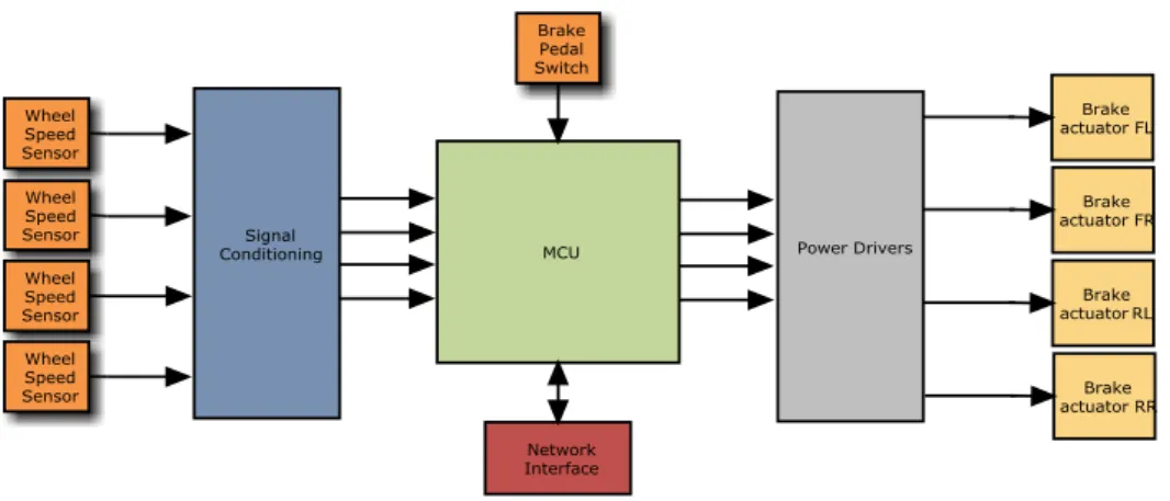
Figure 2.9 illustrates the main blocks that compose an antilock braking system.
The ABS actuates when the driver presses the brake pedal. Hence it requires the knowledge of the state of the brake pedal. A brake switch connected to the microcontroller unit (MCU) serves this purpose.
Signal conditioning circuits are required whenever the range or type of sensors are not suited to the inputs of the microcontroller unit (MCU). This is usually required when the outputs of wheel speed sensors are not in the form of PWM signals, which can be interpreted directly by the MCU.
Whenever the antilock braking system intervenes, the driver must be notified that a potentially dangerous situation has occurred. Furthermore, the ABS must perform self
Braking Systems 13
diagnostics in order to detect faulty units. The network interface serves these purposes, interconnecting the ABS with the systems that perform driver notification.
Figure 2.9 - Architecture of the Antilock Braking System
Figure 2.10 depicts an alternative architecture for the ABS. All sensor acquisition circuitry are placed in a application specific integrated circuit (ASIC). A dedicated microcontroller computes sensor values and, through a network interface such as CAN or Flexray (discussed in Chapter 3) delivers the state of all variables of interest. This enables relieving the main ABS MCU processing requirements. The ASIC can be provided with safety related mechanisms such as temperature sensors, watchdog timers and other safety related devices, so more dependability and computational relief of the ABS is achieved.
Figure 2.10 - Architecture of the Antilock Braking System with an ASIC for sensor processing and distribution
14 In-Vehicle systems
2.3.2 Traction Control System (TCS)
When starting off on low frictional coefficient surfaces, excessive throttle can cause the driving wheels to slip, making it harder or even impossible for the driver to move the vehicle. This situation frequently happens when vehicles start off on icy or wet pavements, as the required throttle to move the vehicle is lesser than the driver with its inputs can perform.
A single drive wheel standing in a low frictional surface is enough to immobilize a vehicle. This is due to the physical properties of the differential gear, the mechanical component that enables torque to be delivered to driving wheels spinning at different speeds. When the wheel which is standing on the low friction surface starts slipping, its torque is zero, which will induce a zero torque on the other wheel coupled to the differential. This causes the vehicle to be immobilized.
Figure 2.11 - Vehicle in a split friction coefficient surface
The TCS prevents wheels from spinning due to excess throttle. It improves forward traction and vehicle stability [13] and is specially required for preventing the situations mentioned above.
TCS can be thought as being the dual of the ABS. The TCS stands for acceleration as ABS stands for braking and therefore, while the ABS limits braking force, the TCS limits acceleration. The chart on Figure 2.12 illustrates the duality between the TCS and the ABS. Analogously to what was described when discussing the ABS, stable and unstable values of wheel slip during acceleration exist. When wheel slip during acceleration reaches the unstable zone, the affected wheel experiences a rapid acceleration, and a consequently lower friction coefficient.
The computational unit controlling the TCS monitors wheel speeds during acceleration. Upon detection of a wheel that is spinning or accelerating faster than the others, the TCS enables corrective actions by braking the wheel and requesting for a torque reduction to the motor control unit, so that wheel slip is maintained at all times in the stable zone of the friction/wheel slip chart.
Braking Systems 15
Figure 2.12 - Duality between ABS and TCS [11].
In vehicles equipped with electronic throttle control (ETC), torque reduction is achieved by controlling the throttle electronically. In internal combustion engine vehicles which are not equipped with ETC, torque reduction is achieved by means of reducing/suppressing the spark of one or more cylinders.
As the TCS main composing blocks and principles are shared with the ABS, generally both units operate in the same electronic control unit (ECU).
2.3.3 Electronic Stability Control (ESC)
The electronic stability control (ESC) is an active safety system developed by Bosch in the 90’s and, according to [14], it is extremely successful in reducing not only fatal crashes but also other crash involvements. The United States National Highway Traffic Safety Administration issued a report pointing a reduction in 35% in passenger car accidents and 67% reduction in SUV accidents, both for single car accidents [14]. This crash reduction rate in vehicles equipped with the ESC, made it that every new automobile sold in the United States from 2012 on will have ESC mandatorily.
In optimal conditions where no wheel slip is observed, when a driver steers a vehicle a yaw momentum is generated. This yaw momentum is responsible for the change in the vehicle direction. However, when the vehicle is skidding, i.e. its direction is not congruent with the wheels direction, the generated yaw is diminished and consequently the steering effect. This may result in loss of the vehicle control by the driver.
The slip angle is a measure of the amount of skidding a vehicle is experiencing. Figure 2.13 depicts a skidding vehicle in which the slip angle β can be observed.
16 In-Vehicle systems
Figure 2.13 - Vehicle side slip angle
The relationship between the yaw moment and the slip angle for a set of steering angles varying from -4 to +4 is given on the chart on Figure 2.14.
It can be noticed that the greater the slip angle is, the less effect a steering action by the driver will be actually turned into the pretended steering effect. Also, two different situations can happen: when the required yaw moment is bigger than the actual yaw moment (understeering) and when the required yaw moment is smaller than the actual needed (oversteering). These situations are depicted in Figure 2.15.
Braking Systems 17
Figure 2.15 - Vehicle experiencing under and over steering
The objective of the ESC system is to guarantee that the driver steering intentions are actually performed by the vehicle.
2.3.3.1 ESC Operation
Firstly through vehicle dynamics calculations, the ESC must determine how the vehicle should be behaving with the driver’s inputs. These are the steering wheel angle, the brake pedal pressure and the throttle position.
The vehicle's ideal behavior is then compared with its actual behavior. The actual behavior of the vehicle is obtained with aid of yaw moment sensors, lateral acceleration sensors and wheel speed sensors. If the actual behavior of the vehicle differs from the ideal behavior by a certain amount, called the threshold, the ESC kicks in by sending commands to the motor control ECU and to the brake actuators so a counteracting yaw that compensates the skidding effect is generated.
In case of oversteering and understeering situations, the brake forces applied to stabilize the vehicle are as high as the deviation between the ideal and the actual behavior of the vehicle.
Figure 2.16 illustrates an oversteering situation. As the vehicle direction starts pointing to the center of the curve, the ESC system detects the discrepancy between the driver inputs and the vehicle behavior and tries to minimize it by applying a counteracting yaw moment. This counteracting yaw moment is achieved by applying brake pressure on the right front wheel. As expected, if this discrepancy raises, so the counteracting yaw must raise and therefore the brake pressure is increased on sequence 3. As the vehicle goes back to the desired direction, the brake pressure on the right front wheel is progressively decreased until the vehicle behavior corresponds to the driver inputs.
18 In-Vehicle systems
Figure 2.16 - ESC operation during over steering
Figure 2.17 depicts an understeering situation. Despite the driver's intention to steer the vehicle, the vehicle doesn’t respond in the way it should and it starts moving towards the outer part of the curve. Once the ESC detects this behavior it tries to compensate by creating a counteracting yaw by applying brake pressure on the rear left wheel. Just like in the previous example this force is as big as the difference between the actual behavior and the desired.
Figure 2.17 - ESC operation during understeering
2.3.3.2 ESC Architecture
Figure 2.18 illustrates a possible architecture for an ESC system. Due to the fact that the value of lateral acceleration and yaw sensors can be required by other systems, these might be placed on a dedicated ASIC embedding all the requiring components for their acquisition. Being dependent on other systems for its operation, the ESC is connected to the required systems by means of a network interface. The steering wheel position value is often transmitted by the power steering ECU.
Braking Systems 19
Figure 2.18 - Electronic Stability Control architecture
2.3.4 Electronic Brake Force Distribution (EBD)
EBD allows vehicles to stop in shorter distances by distributing brake force according to the distribution of weight among the vehicle [15].
Due to the fact that weight is not evenly distributed in vehicles, each wheel supports a different load. The load that a wheel has to support is also dependent on the dynamics of the vehicle. When braking in a straight line the weight shifts from the rear to the front of the vehicle while when braking during turns the weight is shifted to the outer part of the vehicle in relation to the turn. The more weight a wheel is supporting, the better grip it has and therefore the more braking force can be applied to it. The EBD takes advantage of this physical fact.
The EBD adjusts the ratio between front/rear or left/right brake forces so the braking effect is maximized. Wheel speeds are constantly monitored and, upon detection of wheel slip due to low load, brake force is increased on higher loaded wheels.
The EBD can be seen as an upgrade of the ABS system as it uses the same components and therefore only a change in the algorithm is needed to implement an EBD braking system [16].
20 In-Vehicle systems
Figure 2.19 - EBD applying more brake force at the front wheels in a front engine car
2.3.5 Electronic Brake Assist (EBA)
When facing a sudden obstacle the driver has a limited time to react and press the brakes to avoid a collision. Even if the driver's reaction is promptly, the force which is applied to the brake pedal might not be enough to stop the vehicle on time. Several studies have concluded that drivers do not apply sufficient brake force in emergency situations [17]. This fact can be originated by several factors, such as emotional stress created by the unexpected situation, bad seat position and many others.
Assisted braking minimizes braking distance in critical situations by detecting emergency braking intentions and applying maximum braking force. Emergency braking can be detected as drivers tend to press the brake pedal much faster in critical situations. Analogously, when the throttle pedal is quickly released, the EBA control unit can detect this situation and apply brake force. More complex approaches consist in building a model of the driver's behavior under normal circumstances and monitor for abnormal behavior such as the situations described.
Figure 2.20 illustrates the principle of operation of the EBA. The system detects an abnormally fast brake pedal depression and outputs maximum brake force, which is afterwards modulated by the ABS.
Instrument Panels 21
2.3.6 Architecture of Braking ECUs
All of the systems described from Sections 2.3.1 through Sections 2.3.5 are usually embedded in the same ECU. Hence, an architecture capable of serving the operation of the referred systems was already presented in Figure 2.18.
In a small minority of the studied wiring diagrams from different manufacturers, it was observed that the ESC and TCS can be implemented in separate control modules. In these cases, the interaction between the ESC or TCS and the ABS brake unit, where the BA and EBD are implemented, is done by means of a communication network. When required, these systems request braking actions to the ABS unit so its task can be accomplished.
2.4 Instrument Panels
Displaying the right information to the driver is crucial for the good handling and management of the vehicle. It permits the driver to have a better perception of his driving, adapt it according to the surrounding conditions and be aware of problems with the vehicle that can result in undesirable or dangerous situations.
In this section, the data that must be presented to the driver, its sources and how these interconnect with the instrument panel are presented.
2.4.1 Information to Display
2.4.1.1 Vehicle Speed
Drivers naturally sense vehicle speed through a combination of their sensations: their vision, engine noise, and handling feel, or road feel as it is commonly known. However, vehicles are becoming more comfortable and some of the features that contribute to a more comfortable vehicle are enemies from the drivers' speed perception. Vehicles are becoming less noisy due to a better engine/motor performance and a better cabin noise insulation. At the same time almost every vehicle is equipped with power steering or steer by wire systems (in the near future) which shades or eliminates road feel.
This means that the driver's sensorial input signals are being attenuated. In this way, drivers are becoming less likely to have a good prediction about their travelling speed. Also, drivers tend to underestimate their travelling speed which can lead to not respecting speed limits which may lead to a dangerous driving behavior [18]. Therefore, it is crucial for the driver to know its travelling speed as this information serves as feedback for its control attitudes over the vehicle.
The speed of a vehicle is generally acquired in two different ways:
1. Through a vehicle speed sensor that is placed on the transmission and connected to the motor/engine ECU.
22 In-Vehicle systems
2.4.1.2 Motor Revolutions per Minute (RPM)
Motor revolutions per minute provides the driver with an estimation of the effort that is being performed by the motor. It enables the driver to keep that effort below its nominal value and not overload the motor.
RPM can be acquired by means of a rotational speed sensor placed in the motor shaft. This value serves as feedback for the motor control unit and thus, the instrument panel obtains its value by means of a network connection to the motor control ECU.
2.4.1.3 Battery Levels
The driver must be at all times aware of the amount of energy available in the vehicle in order to avoid unpleasant situations. This can be displayed either by means of battery level percentage or/and by an estimation of the number of kilometers. In order to do that the ECU that controls the batteries must be connected to the instrument panel ECU (directly or indirectly).
2.4.1.4 Braking Systems Information
Whenever the ABS, TCS or ESC systems are required to intervene is because the vehicle is facing possible dangerous situations. Despite these systems can avoid certain situations they cannot change the laws of physics to avoid accidents. Therefore the driver must be notified whenever these systems take actions as this is a direct consequence of road conditions and driving style. The computational elements in braking systems are aware of the driving surface and therefore can provide the driver with data that he might not be aware of.
On most of the instrument panels available, this information is displayed in the form of a brake system activity lamp(s), which will be on its on-state when one of the braking system features intervenes or in case of any fault detected upon diagnostic.
2.4.1.5 Tire Pressure
The display of anomalies in tire pressure is a critical matter. Lower than nominal tire pressure causes abnormal heating of the tires, which may result in tire rupture. On the other hand, higher than nominal tire pressure causes excess wear. Tire pressure management systems perform periodic acquisitions of tire pressure and by means of a network connection with the instrument panel ECU, display tire pressures and diagnostics.
2.4.1.6 Lights Status
The status of the vehicle lights is important as the driver might not be able to detect it in certain environments. During daytime and in places where the use of lights is mandatory the driver might not be aware of the lights status due to the abundant luminosity. Also, during the night the type of active lights might not be easily distinguishable depending on luminosity conditions. Therefore, the awareness of lights' status is considered to be important as lighting plays an important role in safety.
2.4.1.7 Motor Diagnostics
The driver should be notified upon detection of any failure or abnormal state on the motor. Diagnosis such as computational failure, excessive motor temperature or sensor failure
Instrument Panels 23
(among all other critical variables) should be in the origin of possible driver alerts, in order for the driver to take appropriate actions to avoid or solve the problem.
2.4.1.8 Systems Status
When vehicles possess features like cruise control systems, speed limitation and others that might affect the control of the vehicle, the driver must be aware of these systems' status.
2.4.2 Instrument Panel Architectures
The following examples of instrument panel architectures are based on real implementations and were adapted for a better understanding of the philosophies involved. Consequently, the number and type of systems connected to the instrument panel is variable and serve as an example only. Although the following diagrams contain more components, only the systems that require its information displayed to the driver are illustrated.
In this section, two different architectures regarding two different philosophies are presented. These are represented in their pure form for a better understanding, as manufacturers often implement solutions that reflect a mixture between these architectures according to their necessities.
2.4.2.1 Point-to-point Architecture
24 In-Vehicle systems
The philosophy behind this architecture consists in hardwiring all the sensors whose variables are to be displayed to the instrument panel ECU. Sensor acquisition is performed by the instrument panel ECU, which controls digital displays, gauges and warning lamps according to the values provided by the sensors. For instance, the engine ECU provides the crankshaft sensor output to the instrument panel ECU so the value of RPM can be computed and displayed.
Warning lamps can be directly actuated by the sources of information. Systems like the supplemental restraint system, ABS, TCS, ESC, lighting systems among others, are commonly hardwired to their respective warning lamps, which are activated upon activity or diagnostic reasons. Warning lamps can also be actuated by the instrument panel ECU, when the input signal provided by the sensor is not in the form of an on/off state and needs to be computed. As an example, the connection between the engine coolant temperature sensor and the instrument panel ECU enables the instrument panel MCU to analyze the engine coolant temperature and actuate the warning lamps accordingly.
2.4.2.2 Networked Architecture
Steering Systems 25
The philosophy inherent to the architecture described on Figure 2.22 consists on integrating the instrument panel ECU in a network connection with the sources of information.
Two different types of networks are connected to the instrument panel ECU. The first, as seen on the left part of Figure 2.22 is a high speed network where the engine ECU, brake ECU and all the dynamic controllers of the vehicle are connected. The second network at the right part of Figure 2.22 is a low speed network where components mainly belonging to the body domain are connected. Just like it was referred on the previous architecture, controllers are directly connected to the lamps as necessary.
The fuel level sensor, lighting switches and others whose values are not required by any ECUs are computed by a multifunction ECU, which transmits its values over the network to the instrument panel.
Variables of interest which have to be displayed and are produced within an ECU are transmitted over the network to the instrument panel ECU. As an example, the crankshaft position sensor is required by the engine ECU as the value of RPM is required for controlling the engine. RPM is computed on the engine control ECU and sent over network so it can be displayed to the driver.
This solution has many advantages comparing to the architecture demonstrated on Section 2.4.2.1:
1 . The number and complexity of wiring is drastically reduced
2 . The number of elements that may be connected with the instrument panel is only limited by the type of network
3 . The complexity of the information that is displayed is higher
4 . The flexibility is higher, as the information to display is not dependent on the number and type of interfaces present on the instrument panel controller.
By integrating the instrument panel ECU in a network with other systems, the ECU can capture messages that are being traded between other systems. For instance, when loss of traction is detected by the TCS, a message is transmitted by the TCS to the motor ECU to reduce torque. The instrument panel ECU can capture this message and display the TCS activity to the driver. In this way, network load and computational efforts are optimized. Additional systems can be integrated by simply connecting them to the corresponding network. Extra sensors that are required for displaying information to the driver can be connected to multifunction ECUs that are connected to the network.
2.5 Steering Systems
The steering system is responsible for transforming the driver's steering intentions into the actual change of vehicle direction. Steering systems have evolved from rather simple mechanical systems to sophisticated intelligent systems that ease the driving, provide more comfort and offer more security.
Steering systems started as purely mechanical systems in which no assistance was provided to aid the driver in steering the wheels. In these systems the driver was the unique source of the force required for overcoming the friction coefficient between the surface and the tires. When the vehicle is stopped or moving slowly, the effort demanded to the driver for
26 In-Vehicle systems
steering the wheels can cause the driving experience to be quite unpleasant. The heavier a vehicle is or the largest its tires are, the more this issue is aggravated.
This situation was later overcame by power steering systems, which are available in the vast majority of vehicles sold nowadays and consist on mechanisms to assist the driver in turning the wheels by amplifying the driver's steering torque inputs [19]. Power steering systems exist mainly in three different kinds: hydraulic, hybrid i.e., a mixture between hydraulic and electric, and electric.
These systems allowed that heavier vehicles or equipped with wider tires could be easily maneuvered, despite the higher frictional forces associated with these characteristics. The mechanical details of such systems are not in the scope of this document, but a simple explanation of each these systems will aid the understanding of the factors and issues involved later in this section.
The last trend in steering systems are the steer-by-wire systems, in which on the contrary of other systems mentioned above, is based on the removal of all mechanical connections between the steering inputs and the steering actuators. Steer-by-wire concepts are described later on Chapter 4.
Four wheel steering is another concept whose popularity is gaining ground, and therefore is also referred in this section.
2.5.1 Hydraulic Power Steering
In hydraulic power steering systems, the assisting force is provided by pressurized fluids. Hydraulic fluid pressure is controlled by a pump which is mechanically coupled with the engine. Therefore, the rotation speed of the pump's rotor depends on engine speed. Figure 2.23 and Figure 2.24 illustrates a hydraulic power steering system applied in a rack-and-pinion configuration.
Steering Systems 27
Figure 2.24 - Power steering hydraulic pump [20]
Hydraulic power steering systems are made in such a way that when the vehicle is idle, there is enough pressure for the steering to be comfortable. This has the consequence that when the vehicle moves faster, more pressure than needed is created, inducing the feeling that the steering is too soft. In order for this pressure not to raise to dangerous levels that could damage the hydraulic circuitry, a pressure relief valve is inserted the hydraulic circuit. A mechanical system that senses the steering intention is connected to hydraulic pressure valves, for enabling the system to provide assistance only when there is an intention to steer the vehicle [21].
As it can be denoted, these systems do not integrate any electronic device and were referred only for contextual reasons.
2.5.2 Hybrid and Electric Power Steering
Both hybrid and electrical power steering systems share the same principles. The difference between them resides on the source of the assisting force. On hybrid power steering systems, the assisting force is provided by hydraulic pressure, by means of an electric pump, while in electrical power steering systems the same is provided by means of an electrical motor.
When the driver intends to steer, it applies a force on the steering input device. Along with the speed of the vehicle, this torque is fed onto the power steering control ECU and the required assistance is evaluated taking these parameters into account. An example of an assisting curve can be depicted on Figure 2.25.
28 In-Vehicle systems
Figure 2.25 - Power steering assist curve [22]
The assisting force must be higher when the vehicle is stopped and tend to zero as speed increases. This enables the driver to have a more precise control of the vehicle.
Power steering systems are mechanically connected in such a way that a computational failure in the system does not cause the driver to lose control of the vehicle, as there is always a mechanical connection between the steering input system and the wheels. However, a faulty element can lead the force providing mechanism to develop a force when it is not supposed to. Such a situation can be dangerous and therefore, steering systems must be provided with fail safe mechanisms.
2.5.2.1 Electro-Hydraulic Power Steering
The electro hydraulic power steering system was developed with two main objectives. The first was the reduction of fuel consumption, associated with the ineffective arrangement consisting on having the hydraulic pump coupled with the engine. Secondly, extra comfort and controllability were demanded, as hydraulic power steering systems' natural assisting curve (in which the steering force rises with vehicle speed) did not offer a satisfactory behavior.
In electro hydraulic power steering systems, the hydraulic pump is driven by an electric motor and not by the engine. Therefore, the hydraulic pressure applied to assist the steering can be regulated by controlling the electric motor.
2.5.2.2 Electric Power Steering (EPS)
Electric power steering systems take advantage of electric motors to provide the assisting steering force. Its working principle is similar to the hybrid power steering system. Comparing with the other solutions discussed, EPS reduces energy consumption, the steering system's weight, provides easier and more powerful control methods [23], and is more environmental friendly due to the elimination of the hydraulic fluid [24].
Steering Systems 29
Figure 2.26 - Electric power steering [24]
2.5.3 Power Steering Architecture
In Figure 2.27 the architecture of a basic power steering architecture can be observed. Although only the basic sensors are represented, other variables can be taken in account to enhance the performance of the power steering system such as a steering angle sensor, steering speed, lateral acceleration, motor temperature among others.
Figure 2.27 - Power steering architecture
Vehicle speed is either obtained by connecting the vehicle speed sensor to power steering MCU or by means of a network connection between the power steering control unit and the motor or brake ECUs.
The power steering ECU is commonly connected to the instrument panel ECU so that diagnostic data can be exchanged. The failure of the power steering system can have catastrophic consequences. Therefore the power steering control unit is commonly suited with fault detection mechanisms which de-energize the steering actuators in case of computational failure.
30 In-Vehicle systems
2.5.4 Four Wheel Steering (4WS)
Ackerman driving is the driving configuration of cars and 4x4 motorcycles. It consists of two wheels that do not steer in the rear and two wheels that steer in the front. Ackerman's principle relies on intersecting at all times the axis of all of the wheels in one point. In case this intersection is not observed, slippage of the wheels occurs [25].
The point where the axis of all wheels intersect is denominated the instantaneous point of curvature. Therefore, as it can be observed by Figure 2.28, inner wheels turn sharper than outer wheels in respect to the curve.
Figure 2.28 : Ackerman drive geometry
Four wheel steering can reduce the instantaneous point of curvature (21% referred on [26]) and provide more mobility to a vehicle. This is useful when the vehicle is moving slowly, so that maneuvers can be made more easily. 4WS enables the reduction of the instantaneous center of curvature by steering the rear wheels in the opposite direction than the front wheels.
Figure 2.29 : 4WD decrease of turning radius
At high speeds, 4WS increases vehicle stability [27]. To achieve that, rear wheels steer in the same direction as the front wheels.
Steering Systems 31
Figure 2.30 - 4WD at high speeds
Figure 2.31 - Increased stability of the 4WS system when compared to 2WS [28]
32 In-Vehicle systems
2.5.4.1 4WS architecture
The four wheel steering architecture is depicted on Figure 2.33. The 4WS MCU analyses the steering wheel position and vehicle speed. After computing the desired rear wheel position, rear wheels are orientated by means of an electric motor.
The steering wheel position can be shared by the power steering ECU by means of a network connection or the steering wheel position sensor can be directly connected to the 4WS control unit.
Figure 2.33 - 4WS architecture
2.6 Exterior Lighting Systems
Lights have the task of illuminating the path to the driver and to assist in evidencing the vehicle's shape, so other drivers are aware of it with the minimum possible effort. According to an issued report by the United States department of transportation, vision contributes with 90% of the information needed to the driver, hence the fact that most of the accidents happen at night, or during bad visibility periods due to poor weather conditions such as rain or fog.
The types of lights that shall be present in a vehicle and the situations that their use is mandatory varies from country to country. The various types of lights that are commonly found in vehicles are:
1. Low beam - Cruising lights that do not obfuscate other drivers and provide enough illumination for night driving
2. High beam - Intense lights that can only be used when the vehicle is not crossing with other vehicles as it produces considerable amounts of glare
3. Daytime running lamps - Mandatory in some countries. Low intensity lights that enable a better perception of the vehicle
4. Directional indicators - Blinking lights that indicate other drivers the intention in changing direction.
5. Brake lights - Give other drivers the information that the vehicle is braking 6. Reverse lights - Provide other drivers with the indication that the vehicle is

![Figure 2.23 - Hydraulic power steering system applied to a rack-and-pinion configuration [20]](https://thumb-eu.123doks.com/thumbv2/123dok_br/19221926.963105/48.892.252.630.719.951/figure-hydraulic-power-steering-applied-rack-pinion-configuration.webp)
![Figure 2.26 - Electric power steering [24]](https://thumb-eu.123doks.com/thumbv2/123dok_br/19221926.963105/51.892.299.671.111.408/figure-electric-power-steering.webp)
![Figure 2.46 - Adaptive Cruise Control maintaining a constant headway time [33]](https://thumb-eu.123doks.com/thumbv2/123dok_br/19221926.963105/63.892.243.719.869.1113/figure-adaptive-cruise-control-maintaining-constant-headway-time.webp)