Science Arts & Métiers (SAM)
is an open access repository that collects the work of Arts et Métiers Institute of Technology researchers and makes it freely available over the web where possible.
This is an author-deposited version published in: https://sam.ensam.eu Handle ID: .http://hdl.handle.net/10985/17655
To cite this version :
Jinyang XU, Ali MKADDEM, Mohamed EL MANSORI - Recent advances in drilling hybrid FRP/Ti composite: A state-of-the-art review - Composite Structures - Vol. 135, p.316-338 - 2016
Any correspondence concerning this service should be sent to the repository
Administrator : [email protected]
Recent advances in drilling hybrid FRP/Ti composite: A state-of-the-art review
Jinyang Xu
a,⇑, Ali Mkaddem
a,b, Mohamed El Mansori
aaMSMP – EA 7350 Laboratoire, Arts et Métiers ParisTech, Rue Saint Dominique BP 508, 51006 Châlons-en-Champagne, France
bDepartment of Mechanical Engineering, KAU, North Jeddah Branch, P.O. Box 80200, 21589 Jeddah, Saudi Arabia
Keywords:
FRP/Ti composite Drilling force Cutting mechanism Drilling-induced damage Wear mechanism High-quality drilling
a b s t r a c t
Hybrid composite stack, especially FRP/Ti assembly, is considered as an innovative structural configura- tion for manufacturing the key load-bearing components favoring energy saving in the aerospace indus- try. Several applications require mechanical drilling for finishing hybrid composite structures. The drilling operation of hybrid FRP/Ti composite, however, represents the most challenging task in modern manufacturing sectors due to the disparate natures of each constituent involved and the complexity to control tool–material interfaces during one single cutting shot. Special issues may arise from the severe subsurface damage, excessive interface consumption, rapid tool wear, etc. In this paper, a rigorous review concerning the state-of-the-art results and advances on drilling solutions of hybrid FRP/Ti composite was presented by referring to the wide comparisons among literature analyses. The multiple aspects of cut- ting responses and physical phenomena generated when drilling these materials were precisely addressed. A special focus was made on the material removal modes and tool wear mechanisms domi- nating the bi-material interface consumption (BIC) with respect of investigating strategies used. The key conclusions from the literature review were drawn to point out the potential solutions and limita- tions to be necessarily overcome for reaching both(i)enhanced control of drilling operation, and(ii)bet- ter finish quality of FRP/Ti parts.
Contents
1. Introduction . . . 317
2. Material properties and characterization . . . 318
2.1. FRP composite phase. . . 318
2.2. Titanium alloy phase. . . 319
2.3. FRP/Ti assembly. . . 319
3. Drilling force characterization . . . 319
4. Cutting mechanisms controlling FRP/Ti drilling . . . 321
4.1. FRP-phase drilling: brittle fracture dominant mechanisms . . . 322
4.2. Interface drilling: interrelated and mixed cutting mechanisms . . . 324
4.3. Ti-phase drilling: plastic-defamation dominant mechanisms . . . 325
5. Drilling-induced damage . . . 325
5.1. Hole damage produced in FRP phase . . . 325
5.2. Interface damage: the weakest boundary region . . . 327
5.3. Hole damage produced in Ti phase . . . 328
6. Tool wear mechanism . . . 329
7. Strategies for high-quality drilling . . . 331
7.1. Cutting parameters . . . 332
⇑Corresponding author at: MSMP – EA 7350 Laboratoire, Arts et Métiers ParisTech, Rue Saint Dominique BP 508, Châlons-en-Champagne 51006, France. Tel.: +33 06 58 75 50 45; fax: +33 03 26 69 91 97.
E-mail addresses:[email protected],[email protected](J. Xu).
7.2. Cutting tool . . . 333
7.3. Cutting environment . . . 335
8. Concluding remarks . . . 335
Acknowledgement . . . 336
References . . . 336
1. Introduction
In modern aerospace industry, the manufacturing sectors are developing hybrid composite stacks to enhance the characteristics of new-generation structures and to continuously motivate the development of mechanical assemblies favoring energy saving.
Material made of multi-layers of fiber reinforced polymer (FRP) and metal alloy (e.g., titanium alloy, aluminum alloy, etc.) is a typ- ical example of hybrid composite configuration. The benefits of such composite-to-metal alliance arise from the ability to combine resistance and to enhance specific characteristics without signifi- cantly increasing the part weight[1–5]. As such, the hybrid com- posite stack provides enhanced material properties so that the attractive aspects of each constituent material are utilized and their weaknesses are avoided. The key advantages to deliver energy saving and to improve system performance have made the material a good candidate to substitute standard composites and single metal alloys in various industrial applications. Aircraft structures subjected to high thermo-mechanical stresses are successfully fabricated with these materials. The wing-fuselage connection of the new-generation Boeing 787 Dreamliner is a typical application.
Among the available configurations of hybrid composite stacks, FRP/Ti coupling (FRP/Ti, FRP/Ti/FRP, Ti/FRP/Ti), was identified as the most popular one due to its best combination of metallurgical and physical properties including high strength-to-weight ratio and
excellent corrosion/erosion resistance [1–8]. In particular, the FRP/Ti stack exhibits a high strength-to-weight ratio with yield strength as high as 830 MPa and a density of roughly 4 g/cm3[9].
Moreover, the FRP/Ti coupling yields also many advantages over the FRP/Al coupling in several aspects such as reduced galvanic cor- rosion, improved specific strength, etc.[10,11]. Such superior prop- erties ensure its key application focused on manufacturing the key load-bearing components of large commercial aircrafts in the mod- ern aerospace industry.
With regard to its assembly, the stacked FRP and Ti phases are usually joined by mechanical fastening technique, which is the principal method currently used for structural component assem- bly with the advantages of good reliability, easy detachability and convenient inspectability[12–15]. It should be noted that in real FRP/Ti configurations, some of them have existed an adhesive layer to combine each phase together, and some others are separated individually without any adhesive layer. Nevertheless, the mechanical fastening is an essential requirement to ensure the tight joining of such multi-phase material. Since the assembly process demands a large number of holes to be drilled out, the good control of drilling becomes crucial for achieving undamaged parts. In addition, the FRP and Ti phases are often stacked together prior to being drilled out in single-shot time. This minimizes the positional errors and favors tight tolerances in actual production.
Nomenclature
a dimensional constant Adel delamination area
Anom nominal area of the drilled hole b dimensional constant
BCC high-temperaturebphase D drill diameter
D11 coefficients for the bending stiffness of FRP laminate D12 coefficients for the bending stiffness of FRP laminate D22 coefficients for the bending stiffness of FRP laminate D66 coefficients for the bending stiffness of FRP laminate Dc equivalent bending stiffness coefficient of FRP laminate Dmax maximum diameter of the delamination area
Dnom nominal hole diameter
DRAT two-dimensional delamination factor E elastic modulus
f feed rate
Fd one-dimensional delamination factor Fda adjusted delamination factor FRP?Ti drilling from FRP phase to Ti phase
GIC critical energy release rate in fracture mode I h dimensional constant
HCP low-temperature
a
phasen spindle speed Pch concentrated force q uniformly distributed force Ra average surface roughness Rz average peak to valley height Rt peak to valley height T material thickness
Ti?FRP drilling from Ti phase to FRP phase tm multi-tool–work interaction time
v
c cutting speed WC tungsten carbidea
used weight inFdaa
r tool rake angle b used weight inFdah fiber orientation k thermal conductivity v Poisson’s ratio / drill point angle w drill helix angle n proportional coefficient Abbreviation
Al aluminum
BIC bi-material interface consumption BUE built-up edge
CVD chemical vapor deposition CTF critical thrust force doc depth of cut
FRP fiber reinforced polymer HSS high-speed steel
MQL minimum quantity lubrication PCD polycrystalline diamond PVD physical vapor deposition TEC thermal expansion coefficient
Ti titanium
Although drilling FRP/Ti stack in single-shot time is beneficial from a manufacturing standpoint[1–3,9], the processing task still remains challenging because of the large disparity in properties of involved phases. For instance, FRP is an anisotropic material con- sisting of two distinct constituents (reinforcing fiber and polymer matrix) with neatly different properties. The reinforcing fiber exhibits elastic-brittle behavior and poor thermal conductivity while the polymer matrix shows ductile behavior. As for the metallic phase, the Ti alloy exhibits poor thermal conductivity, low elastic modulus, and high chemical affinity to most used tool materials in machining. These characteristics usually lead to severe abrasive wear and edge chipping for FRP-phase cutting [16–19]
and serious chip adhesion, intense flank wear and premature tool failure in Ti-phase machining[20,21].
Technically, the key challenges in FRP/Ti stack drilling may arise from the poor conditions of the multi-tool–work interaction associated with the disparate natures of stacked constituents. The non-compliance between the tool–metal interface, on one hand, and the tool–composite interface, on another hand, induces local interface discontinuities and, hence, affects the cutting behavior.
These discontinuities present the major obstacles to be overcome for better controlling of the cutting conditions and proper selection of the tool–work configuration, which consists of the main scientific and technological challenge. Drilling FRP/Ti stack usually produces severe hole damage including induced delamination, matrix degra- dation, fiber pullout, exit burr defect, etc., which leads to a great deal of rejections in the actual production. The drilling action also affects the tool life because of the rapid tool wear. As such, hybrid composite stack drilling becomes a highly-cost and time- consuming task among the manufacturing community.
Although the FRP/Ti assembly has been utilized in industries for several decades, theoretical and experimental results concerning its mechanical/physical responses in drilling are still significantly understudied. Despite a variety of review papers available on interpreting the machining physics of standard FRPs and single titanium alloys[7,22–30], reviews concerning the multi-physical issues of drilling the two stacked constituents (FRP/Ti) are rarely reported. Recently, Krishnaraj et al.[31]had provided a compre- hensive review on drilling of multi-material stacks. The review work made more efforts to review the drilling behavior of separated constituents (composite laminate, titanium alloy and aluminum alloy) rather than to focus on the stacked composite
drilling behavior. Since the scientific advances in this field still con- tinue to develop, pointing out a state-of-the-art involving the research topic can provide a beneficial guide for both current and future work. This is the key incentive that motivates the current review work to treat rigorously the most significant achievements gained in the bi-material drilling. The multi-physical aspects involved in hybrid FRP/Ti drilling have been precisely addressed based on the literature analyses. Moreover, the potential strategies and methods aiming to high-quality drilling of hybrid FRP/Ti stacks are also reviewed.
2. Material properties and characterization 2.1. FRP composite phase
Advanced composite material, such as fiber reinforced polymer (FRP), has been broadly employed in structural components due to its attractive properties including high specific stiffness, high strength, and high corrosion resistance. The main family of FRP laminates widely used in industries includes CFRP (carbon fiber reinforced polymer) laminate [32], GFRP (glass fiber reinforced polymer) laminate [33], and fiber metal laminate (FML) [34].
Among them, the CFRP and GFRP laminates are by far the most- used constituents in a hybrid composite configuration in view of their excellent mechanical properties. The primary constituents in the FRP phase are reinforcing fibers (e.g., carbon, glass, etc.) and polymer matrices (e.g., thermoplastic resin, thermosetting resin, etc.). The fiber is characterized by lightweight, stiff and strong, which contributes to enhancing mechanical and tribologi- cal properties of the material system, while the polymer matrix binds the fibers together, providing load transfer and structural integrity. The mechanical properties of FRP laminates critically depend on the fiber layup along the epoxy matrix. For example, the unidirectional fiber-orientation prepreg ply (UD-ply) shown inFig. 1(a)[27,35]exhibits quite-different mechanical properties along/in perpendicular to the fiber direction, i.e., maximum stiff- ness/strength along the fiber direction and minimum properties in perpendicular to the fiber direction. However, a bi-directional fiber-orientation prepreg ply (woven-ply) presented inFig. 1(b) [27,35]almost has the maximum stiffness/strength along the both directions. For multi-orientation FRP laminates, they are usually made by bonding many prepreg plies together at different fiber
(a) (b)
Transverse direction Polymer matrix
Longitudinal direction Fibers
(c)
19-24 7-12 13-18 25-30 31-36 37-42 43-48 1-6
Ply No. Orientation angle
45rr90°
-45° -45°
90° 45°
0° 0°
Fig. 1.Schematic illustration of the commonly-used FRP composite structures: (a) UD-ply laminate[27,35], (b) woven-ply laminate[27,35], and (c) multi-orientation laminate following the quasi-isotropic stacking sequence of [0°/45°/90°/45°]6S[27,36].
orientations (cross-ply) to gain enhanced properties. Fig. 1(c) shows the scheme of one type multi-orientation FRP laminate fol- lowing the quasi-isotropic stacking sequence of [0°/45°/90°/45°]6s
[27,36]. The most-used stacking sequences in actual production were [0°/45°/90°/45°]s, [45°/0°/135°/90°/45°]s, etc.
The FRP laminate globally exhibits heterogeneous characteris- tic, anisotropy nature, and brittle behavior, which inevitably results in extremely poor machinability of the material. Structural components made of FRP laminates are mostly manufactured in near-net-shape in order to gain accurate dimensional tolerance and to ensure excellent assembly performance, especially in a hybrid composite configuration. The disparate natures of the fiber/matrix system, as well as its inherent heterogeneity, make the machining operation more difficult than conventional metal cutting. Drilling FRP phase in a hybrid composite configuration exhibits more challenging than the standard FRP drilling cases due to the coupled influences arising from the interface cutting and metal-phase cutting. Relevant discussion will be presented in the following sections of the paper.
2.2. Titanium alloy phase
The titanium alloy used in a hybrid stack configuration aims at providing high corrosion resistance and excellent fatigue proper- ties of the assembly. The superior properties of titanium phase pri- marily have a close relation with the presence of its metallurgical matrix characteristics. In the viewpoint of the crystalline state, the titanium exists in two different phases referring to a low- temperature
a
phase (HCP) and a high-temperature b phase (BCC). The HCP structure of titanium affords a limited number of slip or shear planes while the BCC structure has more slip systems, thereby enabling more deformation locally transformed from HCP into BCC. Pure titanium typically undergoes an allotropic transfor- mation probably at 882°C, changing from the low-temperature close-packed hexagonala
phase to the high-temperature body- centered cubicbphase[7]. The allotropic transformation tempera- ture is very sensitive to some certain added elements. For instance, thea
stabilizers such as Al, O, N, Ga, and C elements produce an increase in the temperature while thebstabilizers such as Mo, V, Cu, Cr, Fe, Mn, Ni, ect., produce a decrease of the transformation temperature[37]. In contrast, some other neutral elements like Sn, Si, and Zr have gentle influences on the transformation temperature.Typically, the Ti alloy can be categorized into four basic groups according to its main metallurgical characteristics: (i) commer- cially pure alloy,(ii)
a
and neara
alloy,(iii)a
-balloy, and(iv)b alloy[7,37]. With regard to its machinability, the titanium alloy is still regarded as an extremely difficult-to-cut material in current manufacturing community due to its inherent properties like low thermal conductivity, low modulus of elasticity, high chemical affinity to tool materials, etc. Special issues may arise from the high force/temperature generation, rapid tool wear and poor surface integrity. Moreover, the Ti-drilling operation exerted in a hybrid composite configuration, obtains significant interrelated influences from the composite-phase drilling, making the cutting mecha- nisms more complicated than single Ti ally drilling cases. Detailed discussion will be presented later.2.3. FRP/Ti assembly
The emergency of FRP/Ti assembly aims to overcome the indi- vidual limitations of each constituent involved and to obtain enhanced structural functions. The typical configurations of FRP/
Ti stacks are CFRP/Ti6Al4V and GFRP/Ti6Al4V that are widely used in modern aerospace industry. The composite-metal system usu- ally offers enhanced properties including high strength-to-weight
ratio, higher specific strength, high corrosion resistance, etc., which makes it an ideal substitute for standard composite and single metal applications.
Drilling is indeed one of the most important and fundamental operations prior to the hybrid composite’s application. However, due to the varying properties and poor machinability of the two stacked constituents, drilling FRP/Ti stack with acceptable hole quality poses the most challenging task in modern manufacturing industries. Severe hole damage, excessive interface consumption as well as rapid tool wear are the key problems encountered in drilling. Exploring the drilling behavior and improving the machinability of hybrid FRP/Ti stack play a crucial role in high efficiency-precision machining of the material. To this aim, great motivations have been exploited in order to address deeply the topics, and a large amount of scientific work has been undertaken within the past few decades.Table 1summarizes the key experi- mental studies that have been performed in the open literature concerning FRP/Ti drilling[1,2,9,38–53].
3. Drilling force characterization
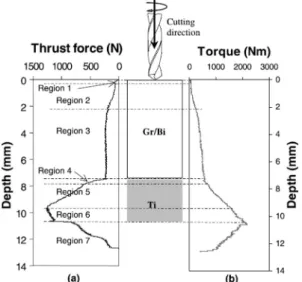
Force generation represents the key cutting characteristics acti- vated in FRP/Ti drilling, which signifies the mechanical energy con- sumption of multi-tool–work interactions governing the chip removal process. In drilling operation, the force generation is usu- ally decomposed into two components, i.e., the thrust-force com- ponent and torque component, which denotes the tribological behaviors between tool–chip interaction and tool–machined sur- face interaction, respectively. Severe force fluctuations in both thrust and torque components are often encountered when drilling hybrid FRP/Ti composite. The force-magnitude discrepancy mainly arises from the fiber orientation’s effects on the FRP-phase drilling, the variable chip separation mode in interface drilling and the serrated chip formation in Ti-phase drilling. The changeable chip formation modes occurring on tool rake face would be the key factor significantly affecting the torque-force component in the stack drilling. The thrust force component, however, signifies the interactions between tool flank face and the machined hole wall surface. In addition, the disparate properties arising from the composite-metal phases also cause the drilling-force signal to exhibit certain stage characteristics.Fig. 2shows the thrust force and torque signals varied with cutting depth when drilling FRP (Gr/Bi)/Ti stack by using standard HSS drill under the fixed cutting conditions ofn =660 rpm andf= 0.2 mm/rev[1]. It is observed that three major regions referring to the FRP, interface and Ti drilling zones in thrust and torque profiles are noticeable. Furthermore, the entire hybrid FRP/Ti drilling action can also be distinguished by seven minor regions (regions 1–7).
Region 1 defines the period when the chisel edge firstly pene- trates the FRP phase. Both the thrust and torque force compo- nents increase gradually from zero.
Region 2 represents that the cutting lips gradually engage in the FRP-phase drilling. The cutting-force signals increase gradually with the tool advancement.
Region 3 signifies the period of full engagement of the drill lips through the FRP-phase drilling. The thrust force and torque nearly keep constant in this region drilling.
Region 4 denotes the period of drill bit involved in the FRP/Ti interface drilling. The tool–work interaction transfers from the absolute tool–FRP interaction, gradually to multi-tool–work interaction and finally to absolute tool–Ti interaction, resulting in the significant increase of the drilling forces.
Region 5 indicates that the cutting lips have gradually cut into the Ti phase, and continuous force elevation has been obtained.
Table 1
Experimental researches concerning hybrid FRP/Ti drilling in the open literature[1,2,9,38–53].
Reference Hybrid composite configuration Drill bit details Cutting conditions Key topics addressed
Ramulu et al.[1] FRP (Gr/Bi)/Ti6Al4V
FRP: IM-6 graphite bismaleimide composite
h= [45°/90°/45°/0°/45°/0°/45°/0°/45°/90°/45°/
0°/45°/0°/45°/90°/45°/90°/90°]s
T= 7.62/3.1 mm
HSS, HSS-Co, carbide twist drills n =325,660,1115,1750,2750 rpm f =0.03,0.08,0.13,0.12,0.25 mm/rev
Drilling forces, Hole production, Tool wear, Hole damage, Surface topography
Brinksmeier and Janssen [2]
AlCuMg2/CFRP/Ti6Al4V h= [45°/90°/0°/45°]s
T= 10/10/10 mm
Uncoated twist drill, Step drills (uncoated, TiB2, diamond) D= 16 mm,
/=130°
w=30°
vc= 10, 20 m/min f =0.15 mm
Cutting environment: dry and oil mist conditions
Workpiece quality, Tool wear
Park et al.[9] CFRP/Ti6Al4V
CFRP: quasi-isotropic graphite/epoxy laminate T= 7.54/6.73 mm
WC twist drills D= 9.525 mm /=135°
w=28°
n =2000, 6000 rpm (CFRP) n= 800, 400 rpm (Ti)
f =0.0762 (CFRP),0.0508 mm/rev (Ti) Cutting environment: dry and wet
Drilling forces, Tool wear, Hole quality
Park et al.[46] CFRP/Ti6Al4V
CFRP: multidirectional graphite epoxy composites T= 7.54/6.73 mm
WC, PCD drills D= 9.525 mm /= 135°
w=28°
n =2000, 6000 rpm (CFRP); 300, 400, 800 rpm (Ti)
f =0.0762 mm/rev (CFRP); 0.0508 mm/rev (Ti) Cutting environment: mist
Drilling forces, Tool wear
Isbilir and Ghassemieh [43]
CFRP/Ti6Al4V CFRP: T700-M21CFRP h= [90°/45°/0°/45°]5s
T= 20/20 mm
AlTiN twist drills D= 8 mm /=140°
w=45°
n =1400 rpm (Ti) and 4500 rpm (CFRP) f =119 mm/min (CFRP) and 457 mm/min (Ti)
Drilling forces, Delamination, Burrs, Surface roughness, Tool wear
Kim and Ramulu[44] FRP (Gr/Bi)/Ti6Al4V
FRP: IM-6 graphite bismaleimide composite h= [45°/90°/45°/0°/45°/0°/45°/0°/45°/90°/45°/
0°/45°/0°45°/90°/45°
/90°/90°]s
T= 7.62/3.1 mm
HSS-Co, split-Point, carbide drills n =660,1115,1750 rpm f =0.08,0.13,0.20,0.25 mm/rev
Drilling process optimization, Hole quality, tool wear
Brinksmeier et al.[39] AlCuMg2/CFRP/Ti6Al4V
CFRP: multilayer of unidirectional prepregs T= 10/10/10 mm
Twist drill, step drill D= 16 mm
vc= 40 m/min vf= 5 mm/min
Cutting environment: minimum quantity lubrication (MQL)
Thermal and mechanical loads, Surface microstructure and damage
Shyha et al.[50] Ti6Al4V/CFRP/Al-7050
h= [45°/0°/135°/90°/45°/0°]s
T= 10/10/10 mm
Uncoated, CVD diamond-coated, C7- coated drills
D= 6.35 mm /=130°
w=30°
20 m/min6vc6120 m/min
f =0.05,0.10,0.15 mm/rev
Cutting environment: wet, spray mist condition
Hole size, Hole surface roughness, Hole edge quality, Microhardness of metal, Chip formation
Ghassemieh[42] CFRP/Ti6Al4V
CFRP: M21E CFRP
C7-coated carbide drills D= 6 mm
n =1400 and 4500 rpm f =119 and 457 mm/min
Drilling forces, Tool wear, Surface roughness
Beal et al.[38] CFRP/Ti6Al4V
CFRP: quasi-isotropic graphite/epoxy laminate T= 7.54/6.73 mm
WC drills D= 9.525 mm /=135°
w=28°
n =400, 800 rpm (Ti) n =2000, 6000 rpm (CFRP)
f =0.0508 mm/rev (Ti) and 0.0762 mm/rev (CFRP)
Cutting environment: wet lubrication condition
Drilling forces, Tool wear, Hole quality, Surface roughness
Park et al.[47] CFRP/Ti6Al4V
CFRP: quasi-isotropic graphite/epoxy laminate T= 7.54/6.73 mm
WC, BAM-coated drills n =2000, 6000 rpm (CFRP); 400, 800 rpm (Ti)
f =0.051 mm/rev
Tool wear, Tool performance
Fujiwara et al.[41] CFRP/Ti6Al4V
CFRP: composed of 1 ply GFRP and 10 ply CFRP T= 3/9.5 mm and 3/10.5 mm
TiAlN, TiSiN and TiAlCr/TiSi-coated drills D= 6 mm
vc= 18.8 m/min f =0.2 mm/rev
Cutting environment: dry and mist-water cooling
Drilling forces, Tool wear, Hole quality
Tashiro et al.[51] CFRP/Ti6Al4V
CFRP: composed of 1 ply GFRP and 10 ply CFRP T= 3/9.5 mm
TiAlN, TiAlCr/TiSi coated drills
D= 6 mm vc= 9.4, 18.8 m/min
f =0.1, 0.2 mm/rev
Cutting environment: dry and water-mist- cooling
Cutting forces, Tool wear, Hole quality, Cutting environment comparison
The maximum thrust force is achieved at the end of this region drilling.
Region 6 demonstrates that the cutting lips have totally cut into the Ti phase.
Region 7 entails the period that the chisel edges have gradually penetrated out of the Ti phase. The thrust force component is found to decrease gradually to zero. However, the torque com- ponent above zero is expected at the end of the process due to tool friction, depending on the elastic springback effect of the composite material.
Moreover, the force generation in FRP/Ti drilling exhibits strong sensitivity to the input variables. Special variables commonly addressed are drilling parameters (spindle speed and feed rate), drilled hole number (tool wear), etc. Ramulu et al.[1]studied the influence of drilling parameters on the force generation when dril- ling FRP (Gr/Bi)/Ti stacks. Results presented inFig. 3(a) andFig. 3(c) indicated that the feed rate had significant effects on the thrust force magnitudes in such manner that a slight increase of feed rate gave rise to the dramatically elevated thrust force, irrespective of the used tool materials. The reason can be attributed to the increased cutting resistance when feed rate was elevated. In con- trast, the relation between spindle speed and thrust force was obscure. And more precisely, the spindle speed was observed to have minor effects on the thrust force generation in all regions except region 7 when using HSS and carbide drills as depicted in Fig. 3(b) and Fig. 3(d), respectively. In other literature [42,43], the spindle speed was confirmed to exhibit positive impacts on the drilling forces for FRP-phase drilling while to have negative impacts on the drilling forces for Ti-phase drilling. The phenomena can be attributed to the hardening or softening effects of the increased high temperature on the work materials caused by the elevated spindle speed, respectively.
In most open literature, drilled hole number (tool wear) was identified as another key factor significantly influencing the dril- ling force generation.Fig. 4shows the experimental results gained by Park et al.[46]when drilling CFRP/Ti6Al4V stacks with WC and PCD drills. It is noticeable that both the thrust force and torque produced in CFRP-phase drilling and Ti-phase drilling exhibit lin- early proportional to the drilled hole number, regardless of the used tool materials. The phenomenon can be explained by the fact that when a large number of holes have been drilled, the tool will suffer excessive and expanded tool wear. As a result, the tool undergoes high tool-work friction coefficient when drilling further uncut chip material, resulting in high cutting energy consumption and subsequent high-force generation. The identical findings were also confirmed by Beal et al.[38], Fujiwara et al.[41], Tashiro et al.
[51]and Wang et al.[52].
4. Cutting mechanisms controlling FRP/Ti drilling
Drilling hybrid FRP/Ti composite exhibits quite different from drilling standard composites and single metal alloys due to the multi-tool–work interaction domains. The disparate natures of each constituent make the chip separation mode more coupled and interrelated governing the bi-material interface consumption (BIC). The interrelated cutting mechanisms play a pivotal role in affecting the machining responses and induced surface quality.
Revealing the mechanisms controlling FRP/Ti drilling can provide a beneficial guide for the cutting-parameter optimization, hole- quality controlling and drill-bit selection.
In FRP/Ti drilling, two different cutting-sequence strategies, i.e., cutting from Ti?FRP and cutting from FRP?Ti, exist from the aspect of tool-entry and tool-exit throughout the material removal process. From the viewpoint of vertical drilling configuration, the reasonable cutting sequence would rest the FRP laminate on top Table1(continued) ReferenceHybridcompositeconfigurationDrillbitdetailsCuttingconditionsKeytopicsaddressed SenthilKumaretal.[49]CFRP/Ti6Al4VSolidWCtwistdrills(withdifferenttool pointangles) /=130° w=30°
n=612and1826rpm f=0.05mm/revToolwear,Chipformation,Effectsofdrill pointangleontoolwear Poutordetal.[48]CFRP/Ti6Al4V T=20.7/25.5mmK20uncoateddrill D=12mm /=140° w=30°
n=2652rpm(CFRP);265rpm(Ti) f=0.05mm/rev(CFRP);0.2mm/rev(Ti)Drillingforces,Toolwear Kuoetal.[45]Ti6Al4V/CFRP/Al-7050 h=[45°/0°/135°/90°/45°/0°]3s T=10/10/10mm
DLCdiamonddrill,CVDdiamonddrill D=6.38mm /=140° w=30°
vc=30m/min(Ti); vc=120m/min(CFRP,Al) f=0.08,0.15mm/rev
Thrustforce,Torque,Toolwear,Hole accuracy,Burrformation Carvajaletal.[40]CFRP/Ti;CFRP/Al; CFRP/CFRPNotspecifiedVariablecuttingconditionsincludingdrilling machine,natureofmaterials,feedrate,spindle speed,etc.
Effectsofdifferentinputfactorsonhole diameter Wangetal.[52]CFRP/Ti6Al4V,Ti6Al4V, CFRP h=[(0°/45°/90°/45°)4(0°/90°/0°/90°)]s T=7.54/6.73mm
Uncoated,AlTiN,nanocompositecoated drills D=9.525mm /=135° w=25°
n=6000rpm,f=0.0762mm/rev(CFRP,CFRP/ Ti); n=500rpm,f=0.0508mm/rev(Ti,CFRP/Ti)
Drillingforces,Toolwearmechanismsin CFRP-only,Ti-onlyandCFRP/Tidrilling MatsumuraandTamura [53]CFRP/Ti T=4/4mmTiAlNcoatedtwistdrill D=6mm /=120° w=20°
vc=10,25m/min,f=0.05,0.1mm/revDrilling-forcemodelsPredictedforces Measuredforces
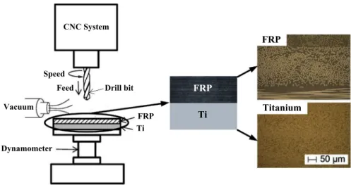
of the Ti alloy and cut from the FRP phase first as illustrated schematically in Fig. 5 [11,46]. This is because in such cutting sequence the Ti alloy can act the role of supporting plate in pre- venting laminate inflection and limiting the workpiece dynamics during the drilling operation. As a result, it can lead to the low-extent delamination occurrence and improved tool life. The beneficial roles of FRP?Ti drilling sequence were also proven by several relevant researches[1,43,46].Fig. 6presents a comparison
of the exit CFRP surface damage generated in drilling standard CFRP laminate without Ti phase and in drilling hybrid CFRP/Ti stack[43]. It was apparent that the CFRP?Ti drilling sequence promoted less fiber pullout (probably near-net shape) than the standard CFRP drilling case. Therefore, following the proposed dril- ling sequence (FRP?Ti), the FRP/Ti drilling mechanisms are then discussed from FRP-phase drilling, to interface drilling and finally to Ti-phase drilling, respectively.
4.1. FRP-phase drilling: brittle fracture dominant mechanisms
In FRP-phase drilling, the cutting mechanisms differ signifi- cantly from conventional metal cutting cases due to the brittleness and heterogeneity of the fiber/matrix system. The mechanisms governing the FRP-phase drilling should be responsible for the specific chip formation mode and chip morphology type.
When drilling FRP phase, material removal occurs through a series of successive fracture aided by diverse nature and uneven load shearing between the matrix and fibers. The chip formation mechanisms of FRP-phase cutting can be basically divided into three categories: (i) layered peeling fracture mechanism when the direction of cutting speed is consistent with the fiber direction;
(ii)extrusion shear fracture mechanism when the direction of cut- ting speed is in an acute angle with the fiber direction; and(iii) bending shear fracture mechanism when the direction of cutting speed is in an obtuse angle with the fiber direction as shown in Fig. 7 [54]. Since brittle fracture operates as the predominant chip separation mode, the resected FRP chips are often produced in the form of ‘‘powdery” dust. However, the chip type generated in dril- ling greatly depends on the properties and volume fraction of the reinforcing fibers. In some cases, the ‘‘continuous” chip formation Fig. 2.Drilling force signals versus cutting depth when drilling hybrid FRP/Ti
composite by using standard HSS drill. (Material: Gr/Bi FRP/Ti6Al4V,h= [45°/90°/
45°/0°/45°/0°/45°/0°/45°/90°/45°/0°/45°/0°/45°/90°/45°/90°/90°]s, cutting parameters:n =660 rpm andf =0.2 mm/rev)[1].
Fig. 3.Thrust forceversusfeed rate and spindle speed when drilling hybrid FRP/Ti composite: (a)n =660 rpm – HSS drill, (b)f =0.0732 mm/rev – HSS drill, (c)n =660 rpm – carbide drill, (d)f =0.0732 mm/rev – carbide drill. (Material: Gr/Bi FRP/Ti6Al4V,h= [45°/90°/45°/0°/45°/0°/45°/0°/45°/90°/45°/0°/45°/0°/45°/90°/45°/90°/90°]s, T = 7.62/3.1 mm)[1].
as like the metal cutting can also be generated. The experimental findings obtained by Hocheng and Puw[55]indicated that when drilling carbon/epoxy the main chip type was absolutely ‘‘discon- tinues” form while for carbon/acrylonitrile butadiene styrene (ABS) drilling, the predominant chip type would be ‘‘continuous”
one. The activated mechanisms controlling the chip characteristics could be explained by the fact that the material removal of the for- mer was governed by brittle fracture while the latter was ruled by
predominant plastic deformation due to the ABS’s capacity of large elongation under cutting loads. In addition, when increasing fiber volume fraction, the majority of the composite materials are removed by a series of fracture due to the non-uniform plastic deformation and thus promoted the formation of ‘‘discontinuous”
chip shape. Moreover, the chip type is also influenced by input cut- ting parameters like feed rate. Results gained by Kim et al. [56]
showed that when low-feed drilling (f =0.02 mm/rev) of PEEK thermoplastic composites, the produced chips were typically ‘‘con- tinuous” and curling for a wide range of speeds due to the high overall toughness of the thermoplastic matrix. In contrast, when higher feed rate was employed (f =0.25 mm/rev), the generated chips were basically ‘‘discontinuous”. Anyway, the mechanisms controlling the chip separation can be identified as the key contrib- utor to the resected chip shape. The chip-separation mechanism dominating the FRP-phase drilling, however, is critically dependent on tool rake angle (
c
), and fiber cutting angle (the angle between the fiber direction and cutting-speed direction). However, these factors are not reviewed here individually since the key objective of the paper aims to survey the mechanism issues focused on hybrid composite drilling. Readers are recommended to refer to the mentioned literature [23,24,27,57–63]. Also, it should be stressed that in drilling, the changeable fiber breaking typeversus Fig. 4.Effects of the drilled hole number on (a) thrust force and (b) torque when drilling hybrid FRP/Ti composite by using WC and PCD drills. (Material: multidirectional graphite epoxy composites/Ti6Al4V,T= 7.54/6.73 mm; cutting tools: WC and PCD with/=135°,w=28°; cutting parameters: WC – high speed:n(CFRP) = 6000 rpm,n(Ti)= 800 rpm; WC-low speed:n(CFRP) = 2000 rpm,n(Ti) = 400 rpm; PCD-low speed:n(CFRP) = 2000 rpm,n(Ti) = 300 rpm;f(CFRP) = 0.0762 mm/rev,n(Ti) = 0.0508 mm/rev;
cutting environment: mist coolant)[46].
Dynamometer
FRP Ti CNC System
Vacuum
Feed Speed
Drill bit FRP
Ti
FRP
Titanium
Fig. 5.Schematic illustration of the FRP?Ti cutting sequence used in vertical drilling of hybrid FRP/Ti composite[11,46].
Minor fiber pullout CFRP
Serious fiber pullout
Delamination
(a)
CFRP/Ti(b)
Fig. 6.CFRP surface damage at the exit side after drilling the 1sthole: (a) drilling of standard CFRP laminate after making the 1sthole and (b) drilling of hybrid CFRP/Ti composite (CFRP?Ti drilling sequence). (Material: CFRP (T700-M21, h= [90°/
45°/0°/45°]5s, T= 20 mm)/Ti6Al4V (T = 20 mm); cutting tool: AlTiN twist drill;
cutting parameters:n =4500 rpm,f =457 mm/min)[43].
h, on one hand, is a key contributor to the severe hole-wall damage formation like inter-ply delamination, fiber pullout, matrix degra- dation, etc. On another hand, it makes the distribution of some local defects, e.g., fiber pullout, delamination, spalling, etc., exhibit regional symmetrical characteristic. Such findings were also con- firmed by some pertinent research work[61,64,65].
4.2. Interface drilling: interrelated and mixed cutting mechanisms In this subsection, a new term ‘‘interface” was introduced to sig- nify the most important zone, i.e., the ‘‘FRP-to-Ti” contact bound- ary, for the illustrations of the hybrid composite drilling process.
The interface region is usually a physically intermediate transition zone that really exists in the bi-material machining process. During interface drilling, the area commonly suffers changeable chip- separation modes and experiences severe mechanical/physical phenomena transition when the tool drilling from FRP phase to Ti phase and vice versa. In such circumstance, the interface drilling should represent the most challenging operation as compared to the FRP-phase cutting and Ti-phase cutting, when drilling hybrid FRP/Ti composite. In FRP/Ti drilling, the bi-material interface machining commonly involves multiple aspects of mechanical/
physical consumption governing the material removal process.
The interrelated BIC makes the region more vulnerable to severe damage formation and defect generation. As the drill bit penetrates into the FRP/Ti interface (as shown inFig. 8), discontinuous tool–
work interaction including tool–FRP coupling and tool–Ti coupling takes place and makes the tool involve in a multi-tool–work inter- action machining. The non-compliance among the tool–work interfaces inevitably gives rise to a particularly harsh cutting condition, and more interrelated cutting behavior governing the drilling operation. The cutting-edge segments as depicted in Fig. 8will then experience a mixed material removal process of fiber brittle fracture and metal plastic deformation simultaneously throughout the multi-tool–work interaction time.
The multi-tool–work interaction time (tm) governing the inter- face drilling, as depicted inFig. 8, is critically dependent on the used drill diameter (D), drill point angle (/), spindle speed (n) and feed rate (f), and can be expressed as follows:
tm¼ D 2nf cot/
2 ð1Þ
During the interface drilling period, the main cutting edges, on one hand, undergo disparate thermal/mechanical responses arising from the multiple tool–work interfaces. On another hand, they experience an dynamic contact transition during the material removal process, i.e., shifting from absolute tool–FRP interaction to multi-tool–work interaction and finally to absolute tool–Ti interaction. As a result, the cutter will suffer intense force fluctua- tion and load vibration, and hence will result in the instability of the tool-work system during the stack drilling. These phenomena can be identified as a main trigger to the hole damage formation concerning the FRP/Ti interface. In addition, since the tool–FRP coupling and tool–Ti coupling exhibit disparate tribological behav- iors, the drill bit in such condition will suffer mixed wear patterns during the interface cutting. The combined wear modes will signif- icantly accelerate the tool wear rate and greatly shorten the tool life.
To alleviate the detrimental effects arising from the interface drilling, reducing the multi-tool–work interaction time would be a direct solution. As shown in Eq.(1), it can be inferred in theory that reducing drill diameter (D), increasing point angle (/), spindle speed (n) or feed rate (f) can lead to the reduction of interface cut- ting time, and hence can promote desirable drilling results. In gen- eral, the interface drilling can be regarded as the most difficult cutting stage as compared to the FRP-phase drilling and Ti-phase drilling. However, to the authors’ best knowledge, the underlying mechanical/physical behavior governing the interface drilling and also the parametric effects on BIC are still not fully understood.
Relevant in-depth researches concerning the issues are rarely Cutting
tool Cutting direction
(b)
FRP laminate Cutting
tool Cutting direction
Chip
FRP laminate
(a)
Cutting tool Cutting direction
(c)
FRP laminate
Fig. 7.Scheme of the chip formation mechanisms in FRP laminate cutting: (a) layered peeling fracture; (b) extrusion shear fracture and (c) bending shear fracture[54].
Fig. 8.Scheme of the drill bit involved in the FRP/Ti interface drilling.
found. The lack of experimental studies on the mentioned topics can be attributed to the difficulty in inspecting the multiple and sophisticated tool–work interaction in actual drilling cases. In the future, great efforts should be made to address deeply the issues.
4.3. Ti-phase drilling: plastic-defamation dominant mechanisms When the drill edges thoroughly cut into the Ti phase, the multi-tool–work interaction absolutely shifts into the tool–Ti interaction. The elastic–plastic deformation then dominates the tool-Ti interaction area. The shearing actions from the thermal/
mechanical effects generate ‘‘continuous” chips that flow on the tool rake face. Under such fixed condition, the drilling process is assumed to reach a steady state for which the cutting force, drilling temperature, and surface integrity could be predicted with an acceptable accuracy. However, since the Ti phase has poor thermal conductivity and strong chemical affinity to the used tool materi- als, the drilling action may cause serious hole damage and catas- trophic tool failure [20,46]. On one hand, the smaller contact area between tool–chip interfaces in Ti drilling often results in stress concentration at the tool edge where the maximum cutting stresses are reached. In addition, the poor thermal conductivity of Ti alloy often results in inefficient heat dissipation and causes intense heat accumulation on tool substrate, which will lead to the severe thermal damage of the tool cutting surface. On another hand, the hot and continuous chips produced in Ti drilling also considerably impair the machined FRP hole and deteriorate the hole quality during their evacuation from the bottom layer.
The detrimental chip evacuation always causes catastrophic abrasion and erosion, and consequently high hole diameter
tolerance in the FRP phase. Such results observed by Brinksmeier and Janssen[2]showed that the scratching effect of Ti chips on the machined CFRP hole could cause a high-depth erosion of approximately 300
l
m when using conventional twist drill in multi-layer AlCuMg2/CFRP/Ti6Al4V stack drilling. To alleviate the chip-evacuation effects, some researchers [1,44] asserted that it was not suggested to employ cutting parameters consisting of low spindle speed and low feed rate in hybrid composite stack dril- ling since these low parametric values favored the formation of‘‘continuous” Ti chips, which would result in a great extent of sub- surface damage in the polymeric holes.
5. Drilling-induced damage
Drilling-induced damage is often characterized by the extent of geometric defects, thermal injuries and physical imperfections. For hybrid FRP/Ti drilling, the induced hole damage comprises both the composite defects (e.g., matrix cratering, inter-ply delamination, fiber pullout, thermal alteration, etc.)[66]and the metallic imper- fections (e.g., hole size error, roundness error, position error, burrs, etc.). The composite-metallic damage usually results in the poor assembly tolerance and long-term performance deterioration of the machined structural components. A list of the commonly addressed hole damage in FRP/Ti drilling is summarized inTable 2.
Fig. 9 [3,44]shows the schematic diagram of the drilling-induced hole damage distribution in FRP/Ti stack.
5.1. Hole damage produced in FRP phase
In FRP phase drilling, damage formation commonly occurs through a series process of matrix cracking, fiber fracture and inter-laminar delamination, etc. Due to the heterogeneity and ani- sotropy of the fiber/matrix system, severe hole damage is often promoted in drilling. Generally, the drilling-induced damage of the FRP phase can be classified into the following categories: geo- metric defects, temperature-related damage, delamination at drill- entry and drill-exit[67]. The tool geometry related damage is asso- ciated with the angle between the fiber orientation and the cutting edge. The temperature-induced damage including micro crack, resin loss, and matrix degradation is commonly produced by the thermal effects of drilling heat on the hole wall surface. In contrast, the damage due to delamination is usually a matter of greatest concern as it affects surface finish and work strength significantly
Fig. 9.Schematic diagram of the hole damage distribution in hybrid FRP/Ti drilling[3,44].
Table 2
Commonly-induced hole damage types when drilling hybrid FRP/Ti composite.
Phase type Drilling-induced damage
FRP phase Matrix cratering, delamination, fuzzing, micro crack, fiber/matrix debonding, spalling, fiber pullout, fiber breaking, resin loss, surface cavities, thermal alteration, etc.
FRP/Ti interface Discoloration ring, damage ring, delamination, etc.
Ti phase Hole size error, roundness error, position error, surface drag, burr, cracking, feed marks, tearing surface, debris of microchips, surface plucking, deformed grains, surface cavities, etc.
leading to a great deal of part rejections. The delamination depends on not only the fiber/matrix nature but also its adjacent properties [68,69]. Note that in standard FRP drilling, two mechanisms responsible for delamination occurrence may operate at both the entry and exit of the drilled hole periphery, which are well- known as ‘‘peel-up delamination” and ‘‘push-out delamination”, respectively. However, in hybrid FRP/Ti stack drilling, especially under FRP?Ti drilling sequence, the peel-up delamination may become a predominant mode while the push-out delamination exhibits less possibility to happen due to the beneficial effects of the bottom-supporting Ti phase on preventing the inflection and deformation of the upper composite laminate. Qi et al.[70]further revealed that the bottom-supporting metal thickness also has sig- nificant effects on the push-out delamination formation, especially when the metal thickness exceeds a so-called critical value (a spec- ified thickness threshold for the free-delamination occurrence) no push-out delamination takes place. For peel-up delamination, as the drill bit cuts into the FRP phase, the drill cutting edges abrade the laminate. In such circumstance, a concentrated peeling force will be formed through the slope of the drill flutes and then sepa- rates the fiber plies from the uncut portions beneath the tool form- ing a delaminated zone around the hole entry periphery, as illustrated inFig. 10.
Since the delamination belongs to an irreparable damage and an inter-ply failure, it is recognized as the most critical damage that severely impairs the performance of the machined components and accounts for probably 60 % of the part rejections in the aero- space industry[27,55,67,71–73]. In general, it is believed by many scholars[70,74–76]that there exists a critical thrust force (CTF) in composite drilling or composite/metal drilling, below which no delamination takes place. For detailed information about CTF,
readers are recommended to refer to the mentioned literature [70,74–76]. In order to predict the CTF in hybrid composite drilling, Qi et al.[70]established the analytical models based on the linear elastic fracture mechanics, classical bending plate theory and clas- sical lamination theory. In their proposed models, the CTF (P) responsible for the push-out delamination is simplified as a resul- tant force of a concentrated one (Pch) at the chisel edge and a uni- formly distributed oneqat the cutting lips[77]. Both CTF models in two drilling sequences, i.e., drilling from metal?FRP and drilling from FRP?metal, were discussed in their research, which are illustrated in Fig. 11 and summarized in Table 3, respectively.
The calculated results showed that when drilling from FRP? metal sequence, the CTF yielded a higher value than that operated from metal?FRP sequence. The phenomenon indicated that dril- ling sequence of FRP?metal would be more beneficial for mini- mizing delamination when drilling hybrid composite stacks. The predicted results showed consistent agreement with their experi- mental validation. However, the established models were restrained to solely predicting the CTF of conventional twist drill in drilling hybrid FRP/metal composite and ignored some internal factors like the effects of composite layup and plate shape on push-out delamination.
In addition, the delamination visualization and assessment in hybrid FRP/Ti drilling also pose a challenging task because of its internal-external nature. At present, the most used non- destruction methods for characterizing the size, shape, and loca- tion of delamination are optical microscopy, ultrasonic C-Scan, and X-ray computerized tomography[72,75,76,78–82]. For delam- ination extent, it is often evaluated by using one-dimensional delamination factor (Fd)[16,65,76](signify the delamination eval- uation based on the one-dimensional scale: diameter, the ratio of
(a) (b)
FRP Metal Metal
FRP
P P
Pch
a
q
2a
2a
2b Pre
2a Pre
Pch P
Pre2a 2b 2b2a
r θ L
Fig. 11.Delamination analysis for different cutting-sequence strategies applied in hybrid FRP/metal drilling: (a) metal?FRP cutting sequence and (b) FRP?metal cutting sequence[70].
Thrust force
FRP phase
Ti phase Peel-up delamination Peel-up delamination
Matrix bonding
Fiber plies
Interface
Fig. 10.Schematic illustration of the peel-up delamination occurred in hybrid FRP/Ti drilling (FRP?Ti drilling sequence).
the maximum diameter (Dmax) of the delamination area to the hole nominal diameter (Dnom)), two-dimensional delamination factor (DRATorDF)[17,83,84](denote the delamination evaluation based on the two-dimensional scale: area) and adjusted delamination factor (Fda) [85] (signify the comprehensive consideration of bothFdandDRAT) as summarized inTable 4. The main differences among the three criteria relay on fact that the one-dimensional delamination factor represents the simplest way to evaluate the delamination extent induced in real production while the two-dimensional and adjusted delamination factors can accurately assess the real extent of delamination damage since they minimize the influences of a few peeled-up or pushed-down fibers on the delamination measurement.
5.2. Interface damage: the weakest boundary region
In FRP/Ti drilling, the interface linking composite and metal boundaries would be the weakest region vulnerable to severe
damage formation due to the unstable cutting process resulting from the non-compliance tool–work interactions. When the cut- ting tool reaches the interface region, the tool tips and cutting edges suffer severe shocks and vibrations due to the changeable chip separation modes from tool–FRP interaction to tool–Ti interaction and vice versa. Such physical phenomenon makes the drilling operation much easier to promote damage formation.
Generally, the interface damage was reported in the form of discoloration ring, damage ring, fiber pullout and delamination as shown inFig. 12 [1]. The mentioned interface damage was often irreparable and fatal, which would promote crack initiation and fatigue fracture during the stack’s assembly process.
Concerning the interface damage formation, several scholars [1,9]have revealed that the cutting heat and chip evacuation are the pivotal factors contributing to the damage initiation and prop- agation. Specific reason can be attributed to the unique physical properties of the Ti phase. Since the Ti alloy is characterized by poor thermal conductivity (ks7–7.9 W m1°C1), the cutting
Table 4
Commonly-used delamination factors for damage evaluation when drilling FRP laminates[16,17,65,76,83–85].
Type of delamination factor Equation expression Remarks Reference
One-dimensionalFd Fd¼DDmaxnom Dmax– maximum diameter of the delamination area;
Dnom– nominal diameter of the drilled hole
Chen[16], Xu et al.[65], Tsao and Hocheng[76]
Two-dimensionalDRATorDF DRAT¼AAnomdel
DF¼AdelAAnomnom100%
Adel– delamination area;Anom– nominal area of the drilled hole
Faraz et al.[17], Davim and Reis[83], Mehta et al.[84]
AdjustedFda Fda¼aDDmaxnomþbAAnomdel a,b– the used weights inFda Davim et al.[85]
Table 3
Analytical models for predicting CTF under different cutting-sequence strategies when drilling hybrid FRP/metal composite[70].
Drilling sequence Scheme of delamination Analytical model of critical thrust force (CTF)
Metal?FRP cutting sequence Fig. 11(a) CTFI¼PI¼2np ffiffiffiffiffiffiffiffiffiffiffiffiffiffiffiffiffiffiffiffiffiffiffiffiffiffiffiffiffiffiffiffiffiffiffiffiffiffiffiffiffiffiffiffiffiffiffiffiffiffiffiffiffiffiffiffiffiffiffiffiffiffiffiffiffiffiffiffiffiffi GICð3D11þ2D12þ3D22þ4D66Þ p
Dc¼13ð3D11þ2D12þ3D22þ4D66Þ
FRP?metal cutting sdequence Fig. 11(b) CTFII¼PII¼nK2p ffiffiffiffiffiffiffiffiffiffiffiffiffiffiffiffiffiffiffiffiffiffiffiffiffiffiffiffiffiffiffiffiffiffiffiffiffiffiffiffiffiffiffiffiffiffiffiffiffiffiffiffiffiffiffiffiffiffiffiffiffiffiffiffiffiffiffiffiffiffi GICð3D11þ2D12þ3D22þ4D66Þ p
K¼ na
2 Dþ2a2 lnabþðbDc2a2Þ 9ð1m2Þb2
2Eh3 þa2bþ2a2 lnabþðbDc2a2Þ
Remarks:GIC– the critical energy release rate in mode I;n-proportional coefficient;D11,D12,D22,D66– coefficients stand for the bending stiffness of the uncut FRP laminate;Dc– the equivalent bending stiffness coefficient of the FRP laminate;v– Poisson’s ratio;E– elastic modulus;a,b,h– dimensional constants as seen in Fig. 11.
Fig. 12.(a) Damage region at the composite/Ti interface, (b) the top view of the damage region, and (c) the side view of the damage region of (b). (Material: Gr/Bi FRP/Ti6Al4V, h= [45°/90°/45°/0°/45°/0°/45°/0°/45°/90°/45°/0°/45°/0°/45°/90°/45°/90°/90°]s,T= 7.62/3.1 mm; (a): cutting tools: HSS, HSS-Co and carbide drills, cutting parameters:
n =1750 rpm,f =0.08 mm/rev; (b) and (c): cutting tool: HSS-Co drill, cutting parameters:n =2720 rpm,f =0.08 mm/rev)[1].
heat generation around the interface can’t be dissipated effectively, which, in turn, induces a local heat concentration at the bi-material interface. The accumulated cutting heat will cause thermal soften- ing and degradation of the FRP/Ti interface. Besides, the produced Ti chips also result in severe scratches and intense abrasions on the bi-material interface, leading to the force-induced delamination. In addition, Ramulu et al.[1]pointed out that the drilled hole number (tool wear) and feed rate also influenced the interface damage. For instance, when lower feed rate was used, larger interface damage was generated due to the longer tool-work engagement resulting in more Ti heat generation accumulated on the interface region.
5.3. Hole damage produced in Ti phase
When the tool edges attack the Ti phase, the previous brittle fracture changes into elastic–plastic shearing, thus the generated surface quality tends to be improved a bit as compared to the FRP-phase drilling. However, the most significant problem in hybrid composite drilling always occurs in this phase due to the poor thermal conductivity of the Ti alloy that leads to the localized heat generation concentrated at the tool–chip interface. The ther- mal congestion inevitably results in high cutting temperature gov- erning the tool active zones, exacerbating the interface damage, burr defect, heat-induced delamination and surface roughness.
The main forms of surface defects reported in literature [21,86–
88]are surface drag, burrs, cracking, feed marks, tearing surface, debris of microchips, surface plucking, deformed grains, surface cavities, etc. These mentioned defects usually have a close relation with the thermal/mechanical influences arising from the drilling action and depend considerably on the used cutting conditions.
For the purpose of FRP/Ti assembly, the burr defect produced in Ti phase may be a key problem compared to other surface damage since it usually leads to further disassembly, deburring and re- assembly of the stack. The burr formation induced in drilling is pri- marily dependent on the tool geometry and tool/work orientation (that is, whether the hole axis is orthogonal or not to the plane of the exit surface of the hole)[89].
Normally, the drilling-induced Ti burrs are often classified into three types, namely type A, type B and type C according to the loca- tion of the initiated crack, as illustrated inTable 5. It was defined by authors Ko and Lee[90], Ko et a
![Fig. 1. Schematic illustration of the commonly-used FRP composite structures: (a) UD-ply laminate [27,35], (b) woven-ply laminate [27,35], and (c) multi-orientation laminate following the quasi-isotropic stacking sequence of [0°/45°/90°/45°] 6S [27,36].](https://thumb-eu.123doks.com/thumbv2/123doknet/19368731.0/4.892.206.673.777.1094/schematic-illustration-commonly-composite-structures-orientation-following-isotropic.webp)
![Fig. 5. Schematic illustration of the FRP ? Ti cutting sequence used in vertical drilling of hybrid FRP/Ti composite [11,46].](https://thumb-eu.123doks.com/thumbv2/123doknet/19368731.0/9.892.139.758.103.355/schematic-illustration-cutting-sequence-vertical-drilling-hybrid-composite.webp)

![Fig. 7. Scheme of the chip formation mechanisms in FRP laminate cutting: (a) layered peeling fracture; (b) extrusion shear fracture and (c) bending shear fracture [54].](https://thumb-eu.123doks.com/thumbv2/123doknet/19368731.0/10.892.172.710.98.237/scheme-formation-mechanisms-laminate-fracture-extrusion-fracture-fracture.webp)
![Fig. 9. Schematic diagram of the hole damage distribution in hybrid FRP/Ti drilling [3,44].](https://thumb-eu.123doks.com/thumbv2/123doknet/19368731.0/11.892.218.691.803.1106/fig-schematic-diagram-hole-damage-distribution-hybrid-drilling.webp)
![Fig. 9 [3,44] shows the schematic diagram of the drilling-induced hole damage distribution in FRP/Ti stack.](https://thumb-eu.123doks.com/thumbv2/123doknet/19368731.0/11.892.63.437.623.765/shows-schematic-diagram-drilling-induced-damage-distribution-stack.webp)

![Fig. 11. Delamination analysis for different cutting-sequence strategies applied in hybrid FRP/metal drilling: (a) metal ? FRP cutting sequence and (b) FRP ? metal cutting sequence [70].](https://thumb-eu.123doks.com/thumbv2/123doknet/19368731.0/12.892.206.680.601.840/delamination-analysis-different-sequence-strategies-drilling-sequence-sequence.webp)
