SPLIT-TYPE, HEAT PUMP AIR CONDITIONERS
SERVICE MANUAL
Model name
<Indoor unit>
Model name
<Indoor unit>
Series PEA
2015
PEA-RP200GAQ PEA-RP250GAQ PEA-RP400GAQ PEA-RP500GAQ PEA-RP250GA PEA-RP400GA PEA-RP500GA
• This manual describes only service data of the indoor units.
CONTENTS
1. TYPES OF INDOOR UNITS···2
2. SAFETY PRECAUTION ···3
3. PART NAMES AND FUNCTIONS···8
4. SPECIFICATIONS ···10
5. DATA ···11
6. OUTLINES AND DIMENSIONS ···13
7. WIRING DIAGRAM ···16
8. REFRIGERANT SYSTEM DIAGRAM ···20
9. TROUBLESHOOTING ···21
10. SERVICE DATA (PARTS NAME) ···33
Indoor unitRemote controller (option)
1 TYPES OF INDOOR UNITS
Service Reference PEA-RP200GAQ
PEA-RP250GAQ PEA-RP400GAQ PEA-RP500GAQ
PEA-RP200GAQ(R2).TH-AF PEA-RP250GAQ(R2).TH-AF PEA-RP400GAQ(R1).TH-AF PEA-RP500GAQ(R1).TH-AF Model name
Specification
SAFETY PRECAUTION 2
Cautions for units utilising refrigerant R410A
CAUTIONS RELATED TO NEW REFRIGERANT
Use new refrigerant pipes.
Make sure that the inside and outside of refrige- rant piping is clean and it has no contamination such as sulfur hazardous for use, oxides, dirt, shaving particles, etc.
In addition, use pipes with specified thickness.
Store the piping to be used during installation indoors and keep both ends of the piping sealed until just before brazing. (Leave elbow joints, etc.
in their packaging.)
Use ester oil, ether oil or alkylbenzene oil (small amount) as the refrigerant oil applied to flares and flange connections.
In case of using the existing pipes for R22, be careful with the followings.
á Be sure to perform replacement operation before test run.
á Avoid using thin pipes.
Charge refrigerant from liquid phase of gas cylinder.
If the refrigerant is charged from gas phase, composition change may occur in refrigerant and the efficiency will be lowered.
Do not use refrigerant other than R410A.
If other refrigerant (R22 etc.)is used, chlorine in refrige- rant can cause deterioration of refrigerant oil etc.
Use a vacuum pump with a reverse flow check valve.
Vacuum pump oil may flow back into refrigerant cycle and that can cause deterioration of refrigerant oil etc.
Use the following tools specifically designed for use with R410A refrigerant.
The following tools are necessary to use R410A refrigerant.
Keep the tools with care.
If dirt, dust or moisture enter into refrigerant cycle, that can cause deterioration of refrigerant oil or malfunction of com- pressor.
Do not use a charging cylinder.
If a charging cylinder is used, the composition of refrigera- nt will change and the efficiency will be lowered.
Flare tool
Electronic refrigerant charging scale Vacuum pump adaptor Size adjustment gauge Gauge manifold
Torque wrench Gas leak detector Charge hose
Tools for R410A Contamination inside refrigerant piping can cause deterio-
ration of refrigerant oil etc.
If dirt, dust or moisture enter into refrigerant cycle, that can cause deterioration of refrigerant oil or malfunction of com- pressor.
If large amount of mineral oil enter, that can cause deterio- ration of refrigerant oil etc.
Ventilate the room if refrigerant leaks during operation. If refrigerant comes into contact with a flame, poisonous gases will be released.
[1] Cautions for service
(1) Perform service after collecting the refrigerant left in unit completely.
(2) Do not release refrigerant in the air.
(3) After completing service, charge the cycle with specified amount of refrigerant.
(4) When performing service, install a filter drier simultaneously.
Be sure to use a filter drier for new refrigerant.
[2] Storage of Piping Material
(1) Storage location
Store the pipes to be used indoors. (Warehouse at site or owner’s warehouse) Storing them outdoors may cause dirt, waste, or water to infiltrate.
(2) Pipe sealing before storage
Both ends of the pipes should be sealed until immediately before brazing.
Wrap elbows and T’s in plastic bags for storage.
* The new refrigerator oil is 10 times more hygroscopic than the conventional refrigerator oil (such as Suniso). Water infiltration in the refrigerant circuit may deteriorate the oil or cause a compressor failure. Piping materials must be stored with more care than with the conventional refrigerant pipes.
OK
OK
NG
NG
No changes from the conventional method, but special care is required so that foreign matter (ie. oxide scale, water, dirt, etc.) does not enter the refrigerant circuit.
Example: Inner state of brazed section
When non-oxide brazing was not used When non-oxide brazing was used
1. Do not conduct refrigerant piping work outdoors on a rainy day.
2. Apply non-oxide brazing.
3. Use a brazing material (BCuP-3) which requires no flux when brazing between copper pipes or between a copper pipe and copper coupling.
4. If installed refrigerant pipes are not immediately connected to the equipment, then braze and seal both ends of them.
1. The new refrigerant oil is 10 times more hygroscopic than the conventional oil. The probability of a machine failure if water infiltrates is higher than with conventional refrigerant oil.
2. A flux generally contains chlorine. A residual flux in the refrigerant circuit may generate sludge.
¥ Commercially available antioxidants may have adverse effects on the equipment due to its residue, etc. When applying non-oxide brazing, use nitrogen.
No changes from the conventional method. Note that a refrigerant leakage detector for R22 cannot detect R407C leakage.
Halide torch R22 leakage detector
1. Pressurize the equipment with nitrogen up to the design pressure and then judge the equipmentÕs airtightness, taking temperature variations into account.
2. When investigating leakage locations using a refrigerant, be sure to use R407C.
3. Ensure that R407C is in a liquid state when charging.
1. Use of oxygen as the pressurized gas may cause an explosion.
2. Charging with R407C gas will lead the composition of the remaining refrigerant in the cylinder to change and this refrigerant can then not be used.
¥ A leakage detector for R407C is sold commercially and it should be purchased.
1. Vacuum pump with check valve
A vacuum pump with a check valve is required to prevent the vacuum pump oil from flowing back into the refrigerant circuit when the vacuum pump power is turned off (power failure).
It is also possible to attach a check valve to the actual vacuum pump afterwards.
2. Standard degree of vacuum for the vacuum pump
Use a pump which reaches 0.5 Torr (500 MICRON) or below after 5 minutes of operation.
In addition, be sure to use a vacuum pump that has been properly maintained and oiled using the specified oil. If the vacuum pump is not properly maintained, the degree of vacuum may be too low.
3. Required accuracy of the vacuum gauge
Use a vacuum gauge that can measure upto 5 Torr. Do not use a general gauge manifold since it cannot measure a vacuum of 5 Torr.
4. Evacuating time
¥ Evacuate the equipment for 1 hour after Ð755 mmHg (5 Torr) has been reached.
[6] Additional refrigerant charge
When charging directly from cylinder
· Check that cylinder for R410A on the market is syphon type.
· Charging should be performed with the cylinder of syphon stood vertically. (Refrigerant is charged from liquid phase.)
[7] Service tools
Use the below service tools as exclusive tools for R410A refrigerant.
No. Specifications
1 Gauge manifold ·Only for R410A
·Use the existing fitting specifications. (UNF1/2)
·Use high-tension side pressure of 5.3MPa·G or over.
2 Charge hose ·Only for R410A
·Use pressure performance of 5.09MPa·G or over.
3 Electronic scale
4 Gas leak detector ·Use the detector for R134a, R407C or R410A.
5 Adaptor for reverse flow check ·Attach on vacuum pump.
6 Refrigerant charge base
7 Refrigerant cylinder ·Only for R410A Top of cylinder (Pink) Cylinder with syphon 8 Refrigerant recovery equipment
Gravimeter
Unit
3 PART NAMES AND FUNCTIONS
● Remote controller (option)
Once the controls are set, the same operation mode can be repeated by simply pressing the ON/OFF button.
● Operation buttons
● Indoor Unit
Air intake duct flange
Air outlet duct flange Air outlet
Air intake
(sucks the air inside the room into the unit)
PAR-21MAA
ON/OFF
FILTER
CHECK OPERATION CLEAR
TEST
TEMP.
MENU BACK MONITOR/SET DAY
CLOCK ON/OFF Set Temperature buttons
Down Up
Timer Menu button (Monitor/Set button)
Mode button (Return button)
Set Time buttons Back Ahead
Timer On/Off button (Set Day button)
Opening the door.
ON/OFF button
Fan Speed button
Filter button (<Enter> button)
Test Run button Check button (Clear button)
Airflow Up/Down button Louver button ( Operation button)
To preceding operation number.
Ventilation button
● Display
For purposes of this explanation, all parts of the display are shown as lit. During actual operation, only the relevant items will be lit.
˚F˚C
˚F˚C
ERROR CODE AFTER
TIMER
TIME SUN MON TUE WED THU FRI SAT ON OFF Hr AFTER
FILTER FUNCTION
ONLY1Hr.
WEEKLY SIMPLE AUTO OFF
Identifies the current operation Shows the operating mode, etc.
* Multilanguage display is sup- ported.
“Centrally Controlled” indicator Indicates that operation of the re- mote controller has been prohib- ited by a master controller.
“Timer Is Off” indicator Indicates that the timer is off.
Temperature Setting Shows the target temperature.
Day-of-Week
Shows the current day of the week.
Time/Timer Display
Shows the current time, unless the simple or Auto Off timer is set.
If the simple or Auto Off timer is set, shows the time remaining.
“Sensor” indication
Displayed when the remote controller sensor is used.
“Locked” indicator
Indicates that remote controller but- tons have been locked.
“Clean The Filter” indicator Comes on when it is time to clean the filter.
Timer indicators
The indicator comes on if the corre- sponding timer is set.
Up/Down Air Direction indica- tor
The indicator shows the direc- tion of the outcoming airflow.
“One Hour Only” indicator Displayed if the airflow is set to weak and downward during COOL or DRY mode. (Operation varies according to model.)
The indicator goes off after one hour, at which time the airflow di- rection also changes.
Room Temperature display Shows the room temperature.
Louver display
Indicates the action of the swing louver. Does not appear if the louver is stationary.
(Power On indicator) Indicates that the power is on.
Fan Speed indicator Shows the selected fan speed.
Ventilation indicator
Appears when the unit is running in Ventilation mode.
Caution
●Only the Power on indicator lights when the unit is stopped and power supplied to the unit.
●If you press a button for a feature that is not installed at the indoor unit, the remote controller will display the “Not Available”
message.
If you are using the remote controller to drive multiple indoor units, this message will appear only if he feature is not present at the parent unit.
●When power is turned ON for the first time, it is normal that “PLEASE WAIT” is displayed on the room temperature indication (For max. 2minutes). Please wait until this “PLEASE WAIT” indication disappear then start the operation.
4 SPECIFICATIONS
Model name
Cooling 1.00
2.0
Heating 1.00
2.0
H W D Hi Lo
kW A
CMM L/s CMM
L/s Pa mmAq
dB(A) dB(A) mm mm mm kg lbs
PEA-RP200GAQ PEA-RP250GAQ
3PH 4W 50Hz 380-415V
Galvanized steel Cross fin coil Centrifugal (direct) o2
0.77 65 1083
52 867 150 15
Remote control & built in 51
48 R1 400 1400
634 70 154
Cooling 1.18
2.3
Heating 1.18
2.3 3PH 4W 50Hz 380-415V
Galvanized steel Cross fin coil Centrifugal (direct) o2
0.77 80 1333
64 1067
150 15
Remote control & built in 52
49 R1 400 1600
634 77 169 Power supply (phase, cycle,voltage)
Input
Running current External finish
Heat exchanger
Operation control & Thermostat Sound level
Drain connection Dimensions
Weight Mode
Fan (drive) o No.
Fan motor output
Airflow
External static pressure Hi Lo
Model name
Cooling 1.55
3.8
Heating 1.55
3.8
H W D
kW A
CMM L/s Pa mmAq
dB(A) mm mm mm kg lbs
PEA-RP400GAQ PEA-RP500GAQ
3PH 4W 50Hz 380-415V
Galvanized steel Cross fin coil Centrifugal (direct) o2
1.3 120 2,000
150 15
Remote control & built in 52
R1 595 1947
764 130 286
Cooling 2.84
5.4
Heating 2.84
5.4 3PH 4W 50Hz 380-415V
Galvanized steel Cross fin coil Centrifugal (direct) o2
1.8 160 2,667
150 15
Remote control & built in 53
R1 595 1947
764 133 293 Power supply (phase, cycle,voltage)
Input
Running current External finish
Heat exchanger
Operation control & Thermostat Sound level
Drain connection Dimensions
Weight Mode
Fan (drive) o No.
Fan motor output Airflow
External static pressure Fan
Fan
DATA 5
5-1. Sound Data
Indoor units
Indoor unit
Position measurement
Measurement point Inlet Outlet
1.5m
2m
1m
PEA-RP200,250: Upper High/Lower Low SPL
dB(A) 63Hz 125Hz 250Hz 500Hz 1000Hz 2000Hz 4000Hz 8000Hz
51 55 54 51 49 47 43 33 27
48 50 50 47 46 44 40 29 21
52 56 55 52 50 48 44 34 28
49 51 51 48 47 45 41 30 22
53 55 54 51 50 48 44 40 31
OCTAVE BAND FREQ.Hz Model
52 53 51 52 50 46 44 39 30
PEA-RP200GAQ
PEA-RP250GAQ
PEA-RP500GAQ PEA-RP400GAQ
5-2. Fan Performance Curve
Indoor units
PEA-RP200GAQ
Fan Performance Curve 50Hz
PEA-RP250GAQ
Fan Performance Curve 50Hz
PEA-RP400GAQ
Fan Performance Curve 50Hz
PEA-RP500GAQ
Fan Performance Curve 50Hz
70.0 80.0 90.0 100.0 110.0 120.0 130.0
(Pa)
(Pa) (Pa)
External static pressure
Air flow
(CMM) 0
50 100 150 200 300
250
110.0
100.0 120.0 130.0 140.0 150.0 160.0 170.0
(Pa)
External static pressure
Air flow
(CMM) 0
50 100 150 200 350 300 250 Hi
Lo
45.0 50.0 55.0 60.0 65.0 70.0
Hi
Lo
0 50 100 150 200 250 300
0 50 100 150 200 250
60.0 65.0 70.0 75.0 80.0 85.0 90.0
External static pressure
Air flow Air flow
(CMM) (CMM)
External static pressure
OUTLINES AND DIMENSIONS 6
Return air sensor A
Rubber bush <Remote controller wiring> Rubber bush <Outdoor unit connection wiring> Rubber bush <Power supply wiring>
A
4- ø12 Holes Drain R1
Top view
Control box
Return air duct flange Supply air duct flange <For hanging bolt M10> [Field supply]
22- ø3.1 Holes
24- ø3 Holes Refrigerant pipe ø9.52 (3/8 braze)
Refrigerant pipe ø25.4 (1 braze)
2pcs.··· 1pc.··· Return air
Left side view
Supply air
Front view
75 55
129 70
42
12434
131
53050
95 250 11
7x130(=910)
10
130
130 4545
31311102
200
10
8x130(=1040) 130020
199
100
40
20
462
144
1284
400
15510001054012604013401400 56539
22 330
145 89
35 130 130 35
634
262 73
1054 10
376
25 100 100 25
Unit : mm
PEA-RP200GAQ
Unit : mm
PEA-RP250GAQ
Rubber bush <Remote controller wiring> Rubber bush <Outdoor unit connection wiring> Rubber bush <Power supply wiring>
A
A4- ø12 Holes Drain R1
Top view
Control box 22- ø3.1 Holes <For hanging bolt M10> [Field supply]
Return air duct flange Supply air duct flange
26- ø3 Holes
Left side view
Supply air
Front view
Return air sensor
2pcs. ··· 1pc. Refrigerant pipe ø12.7 (1/2 braze)
42
144 145
75 70 55
129
124
131
50530
34 130
95 250 11
1302 66 10 1484
7x130(=910)130 4545
200
20
100 20
199
40
1500
462
669X130(=1170)
10
25 100100 25
1010
1540 40146040 255205
376
1000
1600
73 262
400
39565
54634
35 130
89 330
22
130 35
PEA-RP400,500GAQ
45 *2*1 *2*1
Refrigerant pipe ø25.4 (1 braze) [2 places (*1 part)]
Return air sensor (2 places)
Drain R1
24- ø3.1 HOLES
36- ø3 HOLES
Left side view Front view
Top view
Return airSupply air4- ø15 HOLES <For hanging bolt M12> [Field supply]
Return air duct flange Control box Supply air duct flange
A
Rubber bush <Remote controller wiring>Rubber bush <Power supply wiring>
Rubber bush <Outdoor unit connection wiring>
A
<Accessory> ·Pipe cover ··· 4pcs. (For dew condensation prevention of local piping and unit connection.) ·Remote controller ··· 1pc.
81 117 156 117
10
201840 10
406060
61
60 404018001880 50664
525 22
102 22.5
120
4X120(=480) 22.5
595
1824
50764 2801125395
340
188 22
1947
570
40 130 130 40
10
33 29 130
12X130(=1560)291491618
100
42.5130 8X130(=1040)42.5
10
203 320 141
20
425 59
70039
Unit : mm
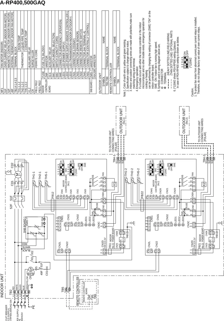
7 WIRING DIAGRAM
PEA-RP200,250GAQ
t˚
t˚
t˚ ON OFF SWE
ON OFF SW1 51F49F X1
52F Lo 52F Hi
TB5 21 1 2 21214321 CN29CN41 CN21 CN20 CN3C
21 3 31 2
1 2
1 2 LED3LED2LED1 DC13.1V21131313
54321 CN51 CN31 CN32 CNDCNDK
CN2L CN22 CN2D DC 13.1V
CN2S 1 2
CNSK 1 3 TAB1
FUSE
ZNR FAN1573
X4 X1X1
X5X6 S1 S2 S3TB4
FB
3
21
52F 1 2 3
Lo Hi52F
L1 L2 L3
TB2 RED WHITE BLACK N
RED WHITE BLACK
TH1 TH2 TH5 4 5
C01
C01 (6P) (Lo)
C02 (3P) (Hi) DSADSR
U U
U U ON OFF (*1)SW2
SNB BOARD 1 CR2CR1
ZNR5~7 1243 OFFON5 (*1)SW2
INDOOR UNIT 1~M TO OUTDOOR UNIT CONNECTING WIRES (POLAR)
OUTDOOR UNIT
21
TE CONTROLLER TB6
BOARDREMOTE CONTROLLER
CONTROLLER BOARDINDOOR INDOOR POWER BOARD
Note:1. Color of earth wire is yellow and green twisting. 2. Specification subject to change without notice. 3. Indoor and outdoor connecting wires are made with polarities,make sure matching wiring and terminal. 4. Emergency operation If a trouble occurs with either the remote controller or the indoor microcomputer and no other trouble exists, emergency operation for cooling or heating can be performed by changing the setting of connector (SWE) "ON" on the indoor controller board. SWE :ON / Indoor fan is running high speed. 5. Symbols used in wiring diagram above are, :CONNECTOR :TERMINAL (HEAVY DOTTED LINE):FIELD WIRING (THIN DOTTED LINE) :OPTIONAL PARTS 6. (*1)SW2 shows PEA-RP250 setting. In case of PEA-RP200 setting is shown as below.
51F NAMEREMOTE CONTROLLER SYMBOL TB6TERMINAL BLOCKCONNECTOR (LOSSNAY) CONNECTOR (CENTRALLY CONTROL)CONNECTOR (HA TERMINAL-A)
CONNECTOR (REMOTE SWITCH)CONNECTOR (DRAIN SENSOR) CN32 CN41 CN51
CN31
CN2L
INDOOR CONTROLLER BOARD
FBFERRITE CORE
X1AUXILIARY RELAY
MAGNETIC CONTACTOR (INDOOR FAN MOTOR<LOW SPEED>)52FLo
MF1 51F 49F TB2,4,5 TH1 TH2
FAN MOTOR (INDOOR) OVER CURRENT RELAY (INDOOR FAN MOTOR) INTERNAL THERMOSTAT (INDOOR FAN MOTOR) TERMINAL BLOCK THERMISTOR FUSEFUSE (T6.3AL250V) ZNRVARISTOR AUXILIARY RELAYX4-6 SW2 SWE LED1LED (POWER SUPPLY) LED2LED (POWER SUPPLY<REMOTE CONTROLLER>) LED3LED (TRANSMISSION<INDOOR·OUTDOOR>)
TH5 SW1
CR1,2SURGE KILLER
MAGNETIC CONTACTOR (INDOOR FAN MOTOR<HIGH SPEED>)52FHi ROOM TEMP LIQUID PIPE TEMP COND/EVA TEMP
SYMBOLNAMEINDOOR UNIT ARRESTERDSA,DSR
VARISTORZNR5~7SNB BOARD 1
CONNECTOR (EMERGENCY OPERATION)
SWITCH (CAPACITY CODE)SWITCH (MODEL SELECTION) Caution, 1.To protect fan motor from abnormal current,over current relays is installed. Therefore, do not change factory set value of over current relays.
54321 53421
PEA-RP200,250GAQR2
t˚
t˚
t˚ ON OFF SWE
ON OFF SW1 51F49F X1
52F Lo 52F Hi
TB5 21 1 2 21214321 CN29CN41 CN21 CN20 CN3C
21 3 31 2
1 2
1 2 LED3LED2LED1 DC13.1V
21131313
54321 CN51 CN31 CN32 CNDCNDK
CN2L CN22 CN2D DC 13.1V
CN2S 1 2
CNSK 1 3 TAB1
FUSE
ZNR FAN1573
X4 X1X1
X5X6 S1 S2 S3TB4
FB
321
52F 1 2 3
Lo Hi52F
L1 L2 L3
TB2 RED WHITE BLACK N
RED WHITE BLACK
TH1 TH2 TH5 4 5
C01
C01 (6P) (Lo)
C02 (3P) (Hi) DSADSR
U U
U U ON OFF (*1)SW2
SNB BOARD 1 CR2CR1
ZNR5~7 1243 OFFON5 (*1)SW2
INDOOR UNIT 1~M TO OUTDOOR UNIT CONNECTING WIRES (POLAR)
PE
Y) Q:15A OUTDOOR UNIT
21
REMOTE CONTROLLER TB6
BOARDREMOTE CONTROLLER
CONTROLLER BOARDINDOOR INDOOR POWER BOARD
Note:1. Color of earth wire is yellow and green twisting. 2. Specification subject to change without notice. 3. Indoor and outdoor connecting wires are made with polarities,make sure matching wiring and terminal. 4. Emergency operation If a trouble occurs with either the remote controller or the indoor microcomputer and no other trouble exists, emergency operation for cooling or heating can be performed by changing the setting of connector (SWE) "ON" on the indoor controller board. SWE :ON / Indoor fan is running high speed. 5. Symbols used in wiring diagram above are, :CONNECTOR :TERMINAL (HEAVY DOTTED LINE):FIELD WIRING (THIN DOTTED LINE) :OPTIONAL PARTS 6. (*1)SW2 shows PEA-RP250 setting. In case of PEA-RP200 setting is shown as below.
51F NAMEREMOTE CONTROLLER SYMBOL TB6TERMINAL BLOCKCONNECTOR (LOSSNAY) CONNECTOR (CENTRALLY CONTROL)
CONNECTOR (HA TERMINAL-A)CONNECTOR (REMOTE SWITCH)
CONNECTOR (DRAIN SENSOR) CN32 CN41 CN51
CN31CN2L
INDOOR CONTROLLER BOARD
FBFERRITE CORE
X1AUXILIARY RELAY
MAGNETIC CONTACTOR (INDOOR FAN MOTOR<LOW SPEED>)52FLo
MF1 51F 49F TB2,4,5 TH1 TH2
FAN MOTOR (INDOOR) OVER CURRENT RELAY (INDOOR FAN MOTOR) INTERNAL THERMOSTAT (INDOOR FAN MOTOR) TERMINAL BLOCK THERMISTOR FUSEFUSE (T6.3AL250V) ZNRVARISTOR AUXILIARY RELAYX4-6 SW2 SWE LED1LED (POWER SUPPLY) LED2LED (POWER SUPPLY<REMOTE CONTROLLER>) LED3LED (TRANSMISSION<INDOOR·OUTDOOR>)
TH5 SW1
CR1,2SURGE KILLER
MAGNETIC CONTACTOR (INDOOR FAN MOTOR<HIGH SPEED>)52FHi ROOM TEMP LIQUID PIPE TEMP COND/EVA TEMP
SYMBOLNAMEINDOOR UNIT ARRESTERDSA,DSRVARISTORZNR5~7SNB BOARD 1
CONNECTOR (EMERGENCY OPERATION)SWITCH (CAPACITY CODE)SWITCH (MODEL SELECTION) Caution, 1.To protect fan motor from abnormal current,over current relays is installed. Therefore, do not change factory set value of over current relays.
54321 53421
PEA-RP400,500GAQ
FUSE
FUSE
t˚
t˚
t˚ t˚ t˚t˚
DSR
U
U UDSA
GREEN/YELLOW (*1)SW2 12
21 43 OFFON5
ON OFF SW1
543 ON OFF SWE
12
21 43 OFFON5
ON OFF SW1
543 ON OFF SWE
49F
X02X01 45 C01
52F
32
1 32
1C02C0152F RED WHITE BLACK
RED WHITE BLACK
BLUE 51F FB22FB12 TB4-1 TB4-2
TH1-2 TH2-2 TH5-2
TH5-1
TH2-1
TH1-1 X2 S3S2S1
FB21
X1
TB5 S3S2
21 S1
FB11
1 2 2121
4321 CN29CN41 CN21 CN20 CN3C
21 3 31 2
1 2
1 2 LED3LED2LED1 X6X5X4 3751 DC13.1V
21131313
ZNR
54321 CN51 CN31 CN32 CNDCNDKFAN
CN2L CN22 CN2D DC 13.1V
CN2S 1 2
CNSK 1 3 DC 13.1V
CN2S 1 2
CNSK 1 3
CN3C
21 3 31 2
1 2
1 2 LED3LED2LED1 DC13.1V
211313
ZNR
54321 CN51 CN31 CN32 CND
CN2L CN22 CN2D
1 2 2121
4321 CN29CN41 CN21 CN20 X6X5X4 375113CNDKFAN
TAB1 TAB1
(*1)SW2
POWER BOARDINDOOR
SNB BOARD 1 (No.2)CONTROLLER BOARDINDOOR INDOOR POWER BOARD
CONTROLLER BOARD
51F CR
ZNR5~7 1243 OFFON5 (*1)SW2
(No.1) (No.2)
(No.1)
INDOOR Note:1. Color of earth wire is yellow and green twisting. 2. Specification subject to change without notice. 3. Indoor and outdoor connecting wires are made with polarities,make sure matching wiring and terminal. 4. Emergency operation If a trouble occurs with either the remote controller or the indoor microcomputer and no other trouble exists, emergency operation for cooling or heating can be performed by changing the setting of connector (SWE) "ON" on the indoor controller board. SWE :ON / Indoor fan is running high speed. 5. Symbols used in wiring diagram above are, :CONNECTOR :TERMINAL (HEAVY DOTTED LINE):FIELD WIRING (THIN DOTTED LINE) :OPTIONAL PARTS 6. (*1)SW2 shows PEA-RP500 setting.(2places) In case of PEA-RP400 setting is shown as below.
M 1~ OLLER ARDOLLER OUTDOOR UNIT OUTDOOR UNIT TO OUTDOOR UNIT CONNECTING WIRES (POLAR)
TO OUTDOOR UNIT CONNECTING WIRES (POLAR) (No.1) (No.2)
CONNECTOR (LOSSNAY) CONNECTOR (CENTRALLY CONTROL) CONNECTOR (HA TERMINAL-A)CONNECTOR (REMOTE SWITCH)CONNECTOR (DRAIN SENSOR) CN32 CN41 CN51
CN31
CN2L TB3,TB8SYMBOLNAME TERMINAL BLOCK
OUTDOOR UNIT
CONNECTOR (EMERGENCY OPERATION)SWITCH (CAPACITY CORD)
SW1SWITCH (MODEL SELECTION) LED (TRANSMISSION<INDOOR·OUTDOOR>)LED3LED (POWER SUPPLY<REMOTE CONTROLLER>)LED2
LED (POWER SUPPLY)LED1SWESW2 ARRESTERDSA,DSRVARISTORZNR5~7SNB BOARD 1
SYMBOLNAME AUXILIARY RELAYX1,2 INDOOR CONTROLLER BOARD
FB21,FB22FB11,FB12FERRITE CORE
COND/EVA TEMPLIQUID PIPE TEMP
ROOM TEMP
52FMAGNETIC CONTACTOR (INDOOR FAN MOTOR) SURGE KILLERCRTH5-1,5-2 VARISTORZNRFUSE (T6.3AL250V)FUSE
INDOOR UNIT THERMISTOR
TERMINAL BLOCKINTERNAL THERMOSTAT (INDOOR FAN MOTOR)
OVER CURRENT RELAY (INDOOR FAN MOTOR)FAN MOTOR (INDOOR) TH2-1,2-2TH1-1,1-2TB2,4-1,4-2,549F51FMF1 X4-6AUXILIARY RELAY NAME
REMOTE CONTROLLER SYMBOL TB6TERMINAL BLOCK Caution, 1. To protect fan motor from abnormal current,over current relays is installed. Therefore, do not change factory set value of over current relays.
U U
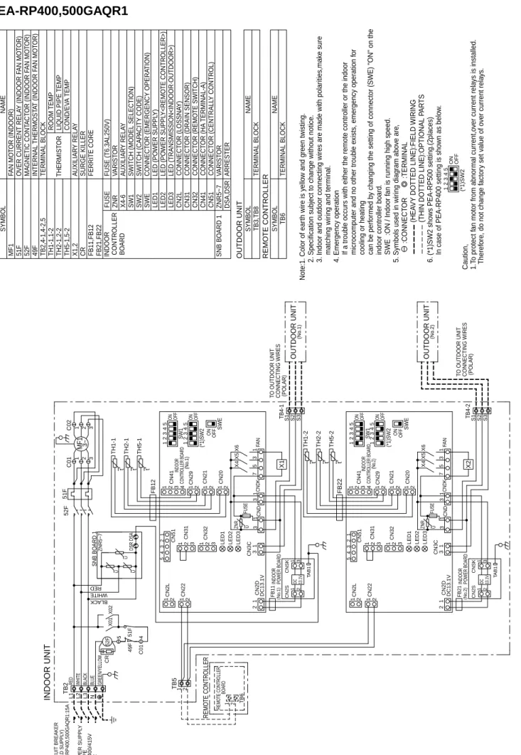
PEA-RP400,500GAQR1
U
U U Note:1. Color of earth wire is yellow and green twisting. 2. Specification subject to change without notice. 3. Indoor and outdoor connecting wires are made with polarities,make sure matching wiring and terminal. 4. Emergency operation If a trouble occurs with either the remote controller or the indoor microcomputer and no other trouble exists, emergency operation for cooling or heating can be performed by changing the setting of connector (SWE) "ON" on the indoor controller board. SWE :ON / Indoor fan is running high speed. 5. Symbols used in wiring diagram above are, :CONNECTOR :TERMINAL (HEAVY DOTTED LINE):FIELD WIRING (THIN DOTTED LINE):OPTIONAL PARTS 6. (*1)SW2 shows PEA-RP500 setting.(2places) In case of PEA-RP400 setting is shown as below.
INDOOR UNIT GREEN/YELLOW (*1)SW2 1221 43 OFFON5
ON OFF SW1
543 ON OFF SWE
1221 43 OFFON5
ON OFF SW1
543 ON OFF SWE
49F
X02X01 45 C01
52F
321 321C02C0152F L1 L2 L3
TB2 RED WHITE BLACK N 21
RED WHITE BLACK
QR1:15A Y BLUE FUSE
51F FUSE FB22FB12 TB4-1 TB4-2
TH1-2 TH2-2 TH5-2
TH5-1
TH2-1
TH1-1 t˚ t˚t˚ X2 S3S2S1
FB21
X1t˚
t˚ t˚
MF1 3~ TB6
TB5 S3S2
REMOTE CONTROLLER
21 S1
FB11
1 2 2121
4321 CN29CN41 CN21 CN20
DSRDSA CN3C
21 3 31 2
1 2
1 2 LED3LED2LED1 X6X5X4 3751 DC13.1V
21131313
ZNR
54321 CN51 CN31 CN32 CNDCNDKFAN
CN2L CN22 CN2D DC 13.1V
CN2S 1 2
CNSK 1 3 DC 13.1V
CN2S 1 2
CNSK 1 3
CN3C
21 3 31 2
1 2
1 2 LED3LED2LED1 DC13.1V
211313
ZNR
54321 CN51 CN31 CN32 CND
CN2L CN22 CN2D
1 2 2121
4321 CN29CN41 CN21 CN20 X6X5X4 375113CNDKFAN
TAB1 TAB1
OUTDOOR UNIT OUTDOOR UNIT
(*1)SW2
POWER BOARDINDOOR (No.1)
SNB BOARD 1 TO OUTDOOR UNIT CONNECTING WIRES (POLAR)
TO OUTDOOR UNIT CONNECTING WIRES (POLAR) (No.2)CONTROLLER BOARDINDOOR (No.2)
(No.1) INDOOR POWER BOARD
BOARDREMOTE CONTROLLER
(No.1)CONTROLLER BOARDINDOOR (No.2)
51F CRZNR5~7 1243 (*1)SW2OFFON5 Caution, 1.To protect fan motor from abnormal current,over current relays is installed. Therefore, do not change factory set value of over current relays.
NAME TERMINAL BLOCK
REMOTE CONTROLLER
CONNECTOR (LOSSNAY) CONNECTOR (CENTRALLY CONTROL)CONNECTOR (HA TERMINAL-A)CONNECTOR (REMOTE SWITCH)CONNECTOR (DRAIN SENSOR) CN32 CN41 CN51CN31CN2L TB6SYMBOLTB3,TB8SYMBOLNAME TERMINAL BLOCK
OUTDOOR UNIT
CONNECTOR (EMERGENCY OPERATION)SWITCH (CAPACITY CODE)SW1SWITCH (MODEL SELECTION) LED (TRANSMISSION<INDOOR·OUTDOOR>)LED3LED (POWER SUPPLY<REMOTE CONTROLLER>)LED2LED (POWER SUPPLY)LED1SWESW2 ARRESTERDSA,DSRVARISTORSNB BOARD 1
SYMBOLNAME AUXILIARY RELAYX1,2 INDOOR CONTROLLER BOARD
FB21,FB22FB11,FB12FERRITE CORE
COND/EVA TEMP LIQUID PIPE TEMPROOM TEMP
52FMAGNETIC CONTACTOR (INDOOR FAN MOTOR) SURGE KILLERCRTH5-1,5-2 VARISTORZNRFUSE (T6.3AL250V)FUSE
INDOOR UNIT THERMISTOR
TERMINAL BLOCKINTERNAL THERMOSTAT (INDOOR FAN MOTOR)
OVER CURRENT RELAY (INDOOR FAN MOTOR)FAN MOTOR (INDOOR) TH2-1,2-2TH1-1,1-2TB2,4-1,4-2,549F51FMF1 X4-6AUXILIARY RELAY U U
ZNR5~7
PEA-RP200GAQ PEA-RP250GAQ PEA-RP400GAQ PEA-RP500GAQ
Unit : mm
Pipe temperature thermistor/liquid (TH2)
Distributor
Condenser/evaporator temperature thermistor (TH5)
Room temperature thermistor (TH1)
Refrigerant flowin cooling Refrigerant flowin heating Strainer
Strainer Heat exchanger
Refrigerant GAS pipe connection Brazing
Refrigerant LIQUID pipe connection Brazing
8 REFRIGERANT SYSTEM DIAGRAM
9 TROUBLESHOOTING
<Error code display by self-diagnosis and actions to be taken for service (summary)>
Present and past error codes are logged and displayed on the wired remote controller or controller board of outdoor unit.
Actions to be taken for service and the inferior phenomenon reoccurrence at field are summarized in the table below. Check the contents below before investigating details.
9-1. TROUBLESHOOTING
Unit conditions at service Error code Actions to be taken for service (summary)
The inferior phenomenon is reoccurring.
Displayed
Not displayed
Judge what is wrong and take a corrective action according to “SELF-DIAGNOSIS ACTION TABLE” (9-2).
Identify the cause of the inferior phenomenon and take a corrective action according to “TROUBLESHOOTING BY INFERIOR PHENOMENA ” (9-3).
The inferior phenomenon is not reoccurring.
Logged
Not logged
1 Consider the temporary defects such as the work of protection devices in the refrigerant circuit including compressor, poor connection of wiring, noise and etc.
Re-check the symptom, and check the installation environment, refrigerant amount, weather when the inferior phenomenon occurred, and wiring related.
2 Reset error code logs and restart the unit after finishing service.
3 There is no abnormality in electrical components, controller boards, and remote controller.
1 Recheck the abnormal symptom.
2 Identify the cause of the inferior phenomenon and take a corrective action according to “TROUBLESHOOTING BY INFERIOR PHENOMENA ” (9-3).
3 Continue to operate unit for the time being if the cause is not ascertained.
4 There is no abnormality in electrical components,
controller boards, remote controller etc.
9-2. SELF-DIAGNOSIS ACTION TABLE
Note: Refer to the manual of outdoor unit for the details of display such as F, U, and other E.
Error Code Meaning of error code and detection method Cause Countermeasure
P1
Abnormality of room temperature thermistor (TH1)
1The unit is in three-minute resume prevention mode if short/open of thermistor is detected. Abnormal if the unit does not reset normally after three minutes. (The unit returns to normal operation, if it has normally reset.) 2Constantly detected during cooling,
drying, and heating operation.
Short: 90:or more Open: -40:or less
1Defective thermistor characteristics.
2Contact failure of connector (CN20) on the indoor controller board. (Insert failure)
3Breaking of wire or contact failure of thermistor wiring.
4Defective indoor controller board.
1~3Check resistance value of thermistor.
0:···15.0k"
10:····9.6k"
20:····6.3k"
30:····4.3k"
40:····3.0k"
If you put force on (draw or bend) the lead wire with measuring resistance value of thermistor breaking of wire or contact failure can be detected.
2Check contact failure of connector (CN20) on the indoor controller board. Refer to 9-6.
Turn the power on again and check restart after inserting connector again.
4Check room temperature display on remote controller.
Replace indoor controller board if there is abnormal difference with actual room temperature.
Turn the power off, and on again to operate after check.
P2
Abnormality of pipe temperature thermistor/Liquid (TH2)
1The unit is in three-minute resume prevention mode if short/open of thermistor is detected. Abnormal if the unit does not reset normally after three minutes. (The unit returns to normal operation, if it has normally reset.) 2Constantly detected during cooling,
drying, and heating (except defrosting) operation.
Short: 90:or more Open: -40:or less
1Defective thermistor characteristics.
2Contact failure of connector (CN21) on the indoor controller board. (Insert failure)
3Breaking of wire or contact failure of thermistor wiring.
4Defective refrigerant circuit is causing thermistor temperature of 90:or more or -40:or less.
5Defective indoor controller board.
1~3Check resistance value of thermistor.
For characteristics, refer to (P1) above.
2Check contact failure of connector (CN21) on the indoor controller board. Refer to 9-6. Turn the power on and check restart after insert- ing connector again.
4Check pipe <liquid> temperature with remote controller in test run mode. If pipe <liquid>
temperature is exclusively low (in cooling mode) or high (in heating mode), refrigerant circuit may have defective.
5Check pipe <liquid> temperature with remote controller in test run mode. If there is exclusive difference with actual pipe <liquid> temperature, replace indoor controller board.
Turn the power off, and on again to operate after check.
P4
Abnormality of drain sensor (DS) 1Suspensive abnormality, if short/open of
thermistor is detected for 30 seconds continuously.
Turn off compressor and indoor fan.
2Short/open is detected for 30 seconds continuously during suspensive abnormality.
(The unit returns to normal operation, if it has normally reset.)
3Detect the following condition.
• During cooling and drying operation.
• In case that pipe <liquid> temperature - room temperature <-10deg
(Except defrosting)
• When pipe <liquid> temperature or room temperature is short/open temperature.
• During drain pomp operation.
1Defective thermistor characteristics
2Contact failure of connector (CN31) on the indoor controller board. (Insert failure).
3Breaking of wire or contact failure of drain sensor wiring.
4Defective indoor controller board.
1~3Check resistance value of thermistor.
0:···6.0k"
10:····3.9k"
20:····2.6k"
30:····1.8k"
40:····1.3k"
2Check contact failure of connector (CN31) on the indoor controller board. Refer to 9-6. Turn the power on again and check restart after inserting connector again.
4Replace indoor controller board if drain pump operates with the line of drain sensor connector CN31-1and 2is short-circuited, and abnormality reappears.
Turn the power off, and on again to operate after check.
Malfunction of drain pump (DP) 1Suspensive abnormality, if thermistor
of drain sensor is let heat itself and temperature rises slightly. Turn off
1Malfunction of drain pump 2Defective drain
Clogged drain pump Clogged drain pipe
1Check if drain-up machine works.
2Check drain function.
3Check the setting of lead wire of drain sensor and check clogs of the filter.
Error Code Meaning of error code and detection method Cause Countermeasure
P6
Freezing/overheating protection is working
1Freezing protection (Cooling mode) The unit is in six-minute resume prevention mode if pipe <liquid or condenser/evap- orator> temperature stays under -15:for three minutes, three minutes after the compressor started. Abnormal if it stays under -15:for three minutes again within 16 minutes after six-minute resume prevention mode.
<Frost prevention mode>
If pipe <liquid or condenser-evaporator>
temperature is 2:or below when 16 minutes has passed after compressor starts operating, unit will start operating in frost prevention mode which stops compressor operation. After that, when pipe <liquid or condenser/evaporator>
temperature stays 10:or more for 3 minutes, frost prevention mode will be released and compressor will restart its operation.
2Overheating protection (Heating mode) The units is in six-minute resume prevention mode if pipe <condenser / evaporator> temperature is detected as over 70:after the compressor started.
Abnormal if the temperature of over 70:is detected again within 10 minutes after six-minute resume prevention mode.
P8
1Slight temperature difference between indoor room temperature and pipe <liquid or condenser / evaporator>
temperature thermistor
• Shortage of refrigerant
• Disconnected holder of pipe
<liquid or condenser / evaporator> thermistor
• Defective refrigerant circuit 2Converse connection of
extension pipe (on plural units connection)
3Converse wiring of indoor/
outdoor unit connecting wire (on plural units connection) 4Defective detection of indoor
room temperature and pipe
<condenser / evaporator>
temperature thermistor 5Stop valve is not opened
completely.
(Cooling or drying mode) 1Clogged filter (reduced airflow) 2Short cycle of air path 3Low-load (low temperature)
operation beyond the tolerance range
4Defective indoor fan motor
• Fan motor is defective.
• Indoor controller board is defective.
5Defective outdoor fan control 6Overcharge of refrigerant 7Defective refrigerant circuit
(clogs)
(Heating mode)
1Clogged filter (reduced airflow) 2Short cycle of air path 3Over-load (high temperature)
operation beyond the tolerance range
4Defective indoor fan motor
• Fan motor is defective.
• Indoor controller board is defective.
5Defective outdoor fan control 6Overcharge of refrigerant 7Defective refrigerant circuit
(clogs)
8Bypass circuit of outdoor unit is defective.
(Cooling or drying mode) 1Check clogs of the filter.
2Remove shields.
4Measure the resistance of fan motor's winding.
Measure the output voltage of fan's connector (Relay for FAN) on the indoor controller board.
∗The indoor controller board should be normal when voltage of AC 220~240V is detected while fan motor is connected.
Refer to 9-6.
5Check outdoor fan motor.
67Check operating condition of refrigerant circuit.
(Heating mode)
1Check clogs of the filter.
2Remove shields.
4Measure the resistance of fan motor's winding.
Measure the output voltage of fan's connector (Relay for FAN) on the indoor controller board.
∗The indoor controller board should be normal when voltage of AC 220~240V is detected while fan motor is connected.
Refer to 9-6.
5Check outdoor fan motor.
6~8Check operating condition of refrigerant circuit.
Abnormality of pipe temperature
<Cooling mode>
Detected as abnormal when the pipe tem- perature is not in the cooling range 3 min- utes later of compressor start and 6 min- utes later of the liquid or condenser/evapo- rator pipe is out of cooling range.
Note 1) It takes at least 9 min. to detect.
Note 2) Abnormality P8 is not detected in drying mode.
Cooling range : -3 deg ] (TH-TH1) TH: Lower temperature between: liquid
pipe temperature (TH2) and con- denser/evaporator temperature (TH5) TH1: Intake temperature
<Heating mode>
When 10 seconds have passed after the compressor starts operation and the hot adjustment mode has finished, the unit is detected as abnormal when
condenser/evaporator pipe temperature is not in heating range within 20 minutes.
Note 3) It takes at least 27 minutes to detect abnormality.
Note 4) It excludes the period of defrosting (Detection restarts when defrost- ing mode is over)
Heating range : 3 deg [ (TH5-TH1)
1~4Check pipe <liquid or condenser / evaporator> temperature with room tem- perature display on remote controller and outdoor controller circuit board.
Pipe <liquid or condenser / evaporator>
temperature display is indicated by setting SW2 of outdoor controller circuit board as follows.
23Check converse connection of extension pipe or converse wiring of indoor/outdoor unit connecting wire.
Conduct temperature check with outdoor controller circuit board after connecting
‘A-Control Service Tool(PAC-SK52ST)’.