If the repair or inspection of the circuit must be carried out without turning off the power, use extreme caution.
SAFETY PRECAUTION
Refer to the flowchart below to determine if the existing piping can be used and if it is necessary to use a filter drier. If the diameter of the existing pipes differs from the specified diameter, please refer to the technological data to confirm whether the pipes can be used. Although the refrigerant piping for R410A is the same as that for R22, exclusive tools are required to avoid mixing different types of refrigerants.
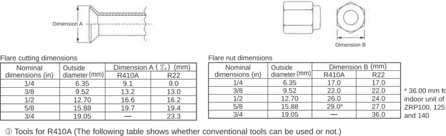
Therefore, to increase hermeticity and strength, the flame cut dimension of the copper tube for R410A is specified separately from the dimensions for other refrigerants, as shown below. The flare nut B dimension for R410A has also been partially changed to increase strength as shown below. Exclusive tool for R410A Exclusive tool for R410A Tool for HFC refrigerant Exclusive tool for R410A Exclusive tool for R410A ester oil and alkylbenzene oil (minimum quantity).
Exclusive tool for R410A. Tools exclusive to R410A Tools for other refrigerants can be used if equipped with reverse flow control adapters Tools for other refrigerants can be used by adjusting the flare dimension Tools for other refrigerants can be used Tools for other refrigerants can be used other coolants Tools for other coolants can be used Tools for other coolants can be used Tools for other coolants can be used. Use the new tool as an exclusive tool for R410A.) : Tools for other refrigerants can be used under certain conditions.
FEATURES
SPECIFICATIONS
DATA
OUTLINES AND DIMENSIONS
WIRING DIAGRAM
WIRING SPECIFICATIONS
If the optional indoor power supply terminal kit is used, change the indoor unit electric box wiring by referring to the figure in the right and the DIP switch settings of the outdoor unit control board. Label affixed near each wiring diagram for the indoor and outdoor units Outdoor unit DIP switch settings (when only separate indoor/outdoor unit power supply is used). Power supply cables and indoor unit/outdoor unit connecting cables must not be lighter than polychloroprene sheathed flexible cable.
Set the lowest number in the group for the outdoor unit whose refrigerant address is “00” as the M-NET address. Note: In group B, the M-NET address of the outdoor unit whose refrigerant address is “00” is not set to the minimum in the group. For A-control models, the M-NET address and refrigerant address may only be set for the outdoor unit.
To build a central control system, the M-NET address setting should be performed only on the outdoor unit. In a system in which several outdoor units are connected, the connector (A, B, S) on the M-NET connection block must be connected separately to another outdoor unit.
REFRIGERANT SYSTEM DIAGRAM
However, this is not a product problem because it is created by the check valve itself due to the small pressure difference in the refrigerant circuit. If “CENTRALLY CONTROLLED” is displayed, refrigerant collection (pumping) cannot be completed normally. Press the exhaust SWP switch (key type) on the control panel of the outdoor unit.
However, even if the unit is stopped and the pump-down SWP switch is pressed less than 3 minutes after the compressor stops, the refrigerant collection operation cannot be performed. Because the device automatically stops after approx. 3 minutes, when the refrigerant collection operation is completed (LED1 off, LED2 on), be sure to quickly close the gas ball valve. If the refrigerant collection operation is completed normally (LED1 off, LED2 on), the unit remains stopped until the power supply is disconnected.
In this case, use refrigerant collection equipment to collect all refrigerant in the system. 7 Turn off the power (circuit breaker), remove the gauge manifold, and then disconnect the refrigerant lines.
TROUBLESHOOTING
Point the remote control at the sensor on the indoor unit and press the HOUR button. Point the remote control at the sensor on the indoor unit and press the ON/OFF button. 1 Check the connection of connector (TH32) on the outdoor control circuit board. Check the break of the lead wire for thermistor).
FUNCTION SETTING
2 Set the indoor unit refrigerant addresses and unit numbers with the F1 to F4 buttons, and then press the button to confirm the current setting. 5 When the settings are complete, press the button to send the setting data from the remote controller to the indoor units. Note: When switching to function selection mode on the wireless remote controller's operating area, the unit automatically exits function selection mode if nothing is input for 10 minutes or longer.
Function selection using the wireless remote control is only available for refrigerant systems with wireless function. Point the wireless remote controller at the receiver of the indoor unit and press the button. Point the wireless remote controller at the sensor of the indoor unit and press the button.
Start this operation when the remote control screen is off.) [CHECK] lights up and flashes. Point the wireless remote control towards the receiver of the indoor unit and press the button. Blinks during remote control startup or when an error occurs.
Manual vane angle Use to set the vane angle for each vane to a fixed position. Function Setting Make the settings for the indoor unit functions via the remote controller as needed. Remote control check When the remote control is not working properly, use the remote control check function to solve the problem.
MONITORING THE OPERATION DATA BY THE REMOTE CONTROLLER ·84
100 Outdoor Unit - Error Delay History 1 (latest) Display delay code is displayed if no delay code is present) Code 101 Outdoor Unit - Error Delay History 2 (previous) Display delay code. 163 Indoor unit-Capacity setting information Refer to Indoor unit-SW3 information Undefined –. indoor control board side) setting. Maintenance data, such as indoor/outdoor unit heat exchanger temperature and compressor operating current can be displayed with "Smooth Maintenance".
Depending on the combination with the outdoor unit, this may not be supported by some models. Compressor Outdoor unit Indoor unit Accumulated operation Heat exchanger 7 Intake air time (<10 hours) temperature (:) temperature. 4 Coolant/heat exchanger temperature COOL :HEAT : 5 Coolant/discharge temperature COOL :HEAT : 6 Air/outside air temperature COOL : HEAT : (Air/discharge temperature) COOL :HEAT.
Air/intake air temperature COOLING : HEAT : (Air/discharge temperature) COOLING :HEAT : 8. Coolant/heat exchanger temperature COOLING :HEAT. 7 Indoor intake air temperature) – (8 Indoor heat exchanger temperature) "D000" is displayed stably on the remote control. If the air conditioner is operated at a temperature range other than the above, but the operation is not stabilized after 30 minutes or more have passed, perform inspection. 3.In heating mode, the operating mode may vary due to frost formation on the outdoor heat exchanger.
7 Indoor intake air temperature)— (8Indoor heat exchanger temperature) (8 Indoor heat exchanger temperature) — (7 Indoor intake air temperature) [5 Discharge temperature] – [4 Outdoor. The service panel is attached to the side panel (R) with a hook on the right side.).
DISASSEMBLY PROCEDURE
Removing the service panel and top panel. 1) Remove the service panel fixing screws (4 for front/ 5 x 12), then slide the service panel down to remove it. To remove the reactor, the electrical parts box must be separated from the outdoor unit.). Refer to procedure no.6 on the next page to remove the
See procedure No. 5 on the previous page to remove the thermistor <2-phase line> (TH6). Remove the 4-way valve coil (21S4), LEV coil (LEV (A)) and high pressure switch wire.
