To repair refrigeration systems, (1-3) through (1-7) must be completed before working on the systems. This should be communicated to the owner of the equipment so that all parties are informed. The regenerated refrigerant must be returned to the refrigerant supplier in the correct recovery cylinder and an appropriate waste drop-off point must be arranged.
The evacuation procedure is carried out before the compressor is returned to the supplier.
OUTLINES AND DIMENSIONS6
WIRING DIAGRAM7
REFRIGERANT SYSTEM DIAGRAM8
Actions to be taken for service, which depend on whether or not the problem recurs in the field, are summarized in the table below.
9-1. TROUBLESHOOTING
TROUBLESHOOTING9
1–4 Check the tube
4 Defective remote control transmitter receiver circuit 5 Defective transmitter receiver. internal control board circuit 6 Noise has entered the transmi-. remote control wire sion.
9-4. TROUBLESHOOTING OF PROBLEMS
3 Normal operation (Each connector on the swing motor side is disconnected or set the fixed wheels by wired remote controller.). 2) LED2 on the indoor control board blinks. 1 Check the connection of remote controller wires in the case of two triple indoor unit system. When the same problem occurs even if indoor control board is replaced, replace wireless remote control board.
9-5. EMERGENCY OPERATION
9-6. HOW TO CHECK THE PARTS
DC Fan Motor (Fan Motor/Internal Controller Circuit) DC Fan Motor Checking Method (Fan Motor Circuit/Internal Controller Circuit) DC Fan Motor Checking Method (Fan Motor Circuit/Internal Controller Circuit) 1 Notes. Do not pull out the motor connector (CNMF) when the power is on. It causes problems with the internal controller PCB and the fan motor.) 2Self-check. Symptom: The fan motor does not stop when you press the stop button on the remote control.
Process: The emergency operation connector on the indoor control board may be set to ON. Power supply check (Remove the connector (CNMF)) Measure the voltage in the indoor controller PCB. Measure the voltage between CNMF 6 and 3 0 V DC and 15 V DC in the indoor controller PCB.
9-7. TEST POINT DIAGRAM Indoor controller board
The pair number settings for the wireless remote control and indoor control board (J41/J42) are listed in the table on the left. in the table indicates the jumper wire is disconnected.).
9-8. FUNCTIONS OF DIP SWITCH AND JUMPER WIRE
10 FUNCTION SETTING
UNIT FUNCTION SETTING BY THE REMOTE CONTROLLER
11 SPECIAL FUNCTION
Rotation and backup OFF (Normal group control operation) Monitoring the request code of the current setting Setting no. Rotation ON (Alternative interval = 28 days) and backup function Rotation ON (Alternative interval = 14 days) and backup function Rotation ON (Alternative interval = 1 day) and back-up function. Rotation ON (Alternative interval = 7 days) and backup function Rotation ON (Alternative interval = 5 days) and backup function Rotation ON (Alternative interval = 3 days) and backup function.
NOTICE
DISASSEMBLY PROCEDURE12
- REMOVING THE PANEL
- REMOVING THE ELECTRICAL BOX
- REMOVING THE INDOOR CONTROLLER BOARD, THE WIRELESS REMOTE CONTROLLER BOARD
- REMOVING THE NOZZLE ASSEMBLY (with VANE and VANE MOTOR) AND DRAIN HOSE
- REMOVING THE INDOOR FAN MOTOR AND THE LINE FLOW FAN
- REMOVING THE PIPE TEMPERATURE
REMOVAL OF THE INDOOR CONTROL BOARD, THE WIRELESS REMOTE CONTROL BOARD THE WIRELESS REMOTE CONTROL BOARD AND THE LED BOARD. REMOVAL OF NOZZLE ASSEMBLY (with VANE and VANE MOTOR) AND DISCHARGE HOSE and VANE MOTOR) AND DISCHARGE HOSE. See procedure 4) (2) Remove 2 screws from the vane motor assembly cover and pull. out of the vane motor unit.
When installing the line flow fan, screw the line flow fan so that there is a 4 mm gap between the right end of the line flow fan and the right wall of the box air passage.
THERMISTOR/LIQUID (TH2) AND COND./EVA
TEMP. THERMISTOR (TH5)
REMOVING THE HEAT EXCHANGER
REMOVING THE ROOM TEMPERATURE THERMISTOR (1) Remove the panel and corner box. (Refer to procedure 1)
13-1. REMOTE CONTROLLER FUNCTIONS
13 REMOTE CONTROLLER
The main screen can be displayed in two different modes: ˝Full˝ and ˝Basic˝. The default setting is ˝Full˝. To switch to ˝Basic˝ mode, change the setting in the main display setting. Appears when the on/off timer, night return or auto off timer function is activated. . displayed when the timer is disabled by the centralized control system. Appears when the thermistor built into the remote control is activated to monitor the room temperature (1).
Most settings (except ON/OFF, mode, fan speed, temperature) can be made from the main menu.
Menu structure
Main menu list Main
Main/Sub When connecting 2 remote controls, one of them must be designated as a sub-controller. Main screen Use to switch between ˝Full˝ and ˝Basic˝ modes for the main screen and use to change the background colors of the screen to black. Automatic mode With the button you can choose whether to use automatic mode or not.
Control code, error source, refrigerant address, model name, production number and contact information (dealer's telephone number) can be displayed. The model name, production number and contact information must be registered in advance to be displayed.). Service Test Run Select “Test Run” from the Service Menu to open the Test Run menu. Select ˝Enter Service Info.˝ from the Service menu to open the Service Information screen.
Settings Function Setting Make the settings for the indoor unit functions via the remote controller as needed. Diagnosis Self-Check: Error history of each unit can be checked via the remote control. Remote control check: When the remote control is not working properly, use the remote control check function to solve the problem.
Controller interface
Display
The control code, fault unit, chiller address, date and time of occurrence, model name and serial number will be displayed. The model name and serial number will only be displayed if the information has been registered.
13-2. ERROR INFORMATION
While no errors occur, page 2/2 of the error information can be viewed by selecting ˝Error Information˝ from the Maintenance menu.
13-3. SERVICE MENU
Test run operation
Auto vane check
13-4. TEST RUN
Measure an impedance between the power terminal block on the outdoor unit and earth with a 500 V megger and check whether it is equal to or greater than 1.0 MΩ. Set the indoor unit refrigerant addresses and unit numbers using the F1 to F4 buttons, then press the [ ] button to confirm the current setting. Use the F1 or F2 button to move the cursor to select the mode number, and change the setting number with the F3 or F4 button.
If the unit is common or when all units are running, all indoor units for the selected refrigerant address will start fan operation. When the transmission is complete, the screen returns to the Function Setting screen. Refer to the indoor unit installation manual for detailed information on the initial settings, mode numbers and setting numbers of the indoor units.
Be sure to write down the settings for all functions if any of the initial settings have been changed after the installation work is completed.
13-5. FUNCTION SETTING
Use the F1 or F2 button to move the cursor to select the mode number, and change the setting number with the F3 or F4 button. lt;Checking indoor unit no.>. When the settings are completed, press the [ ] button to send the setting. data from the remote controller to the indoor units. Check mode is the mode that is activated when you press the CHECK button twice to display.
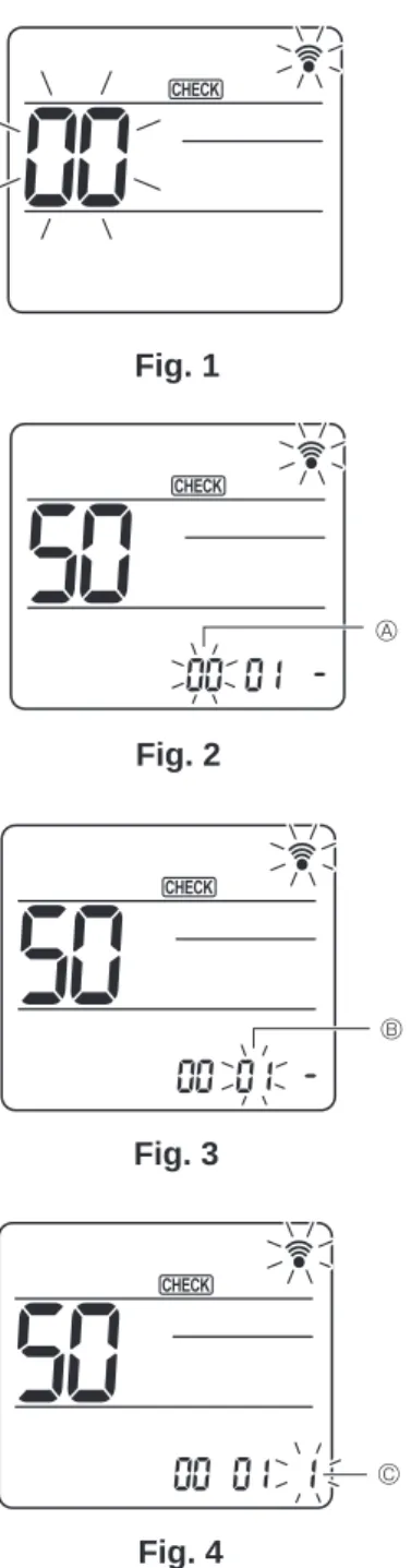
When you switch to function selection mode on the operation area of the wireless remote control, the unit will automatically exit function selection mode if there is no input for 10 minutes or longer. Function selection using wireless remote control is only available for cooling system with wireless function. If the unit number is set to AL, all the indoor units in the same cooling system start performing fan operation simultaneously.
Press the TEMP button once to set ˝50˝. Aim the wireless remote controller at the receiver of the indoor unit and press the. Aim the wireless remote controller at the receiver of the indoor unit and press the min button. Aim the wireless remote controller at the sensor of the indoor unit and press the h button.
Aim the wireless remote control at the indoor unit's receiver and press. Aim the wireless remote control at the indoor unit's receiver and press the button.
13-6. ERROR HISTORY
Unit not exist˝ is displayed if there are no indoor units corresponding to the entered address.
Procedure]
If the operations cannot be completed with the remote controller, diagnose the remote controller with this function. Select ˝Remote Control Check˝ from the Diagnostics menu and press the [ ] button to start the remote control check and view the check results. To cancel the remote control control and exit the ˝Remote Control Control˝ menu screen, press the [ ] or [ ] button.
Nothing will appear on the remote control display if the correct voltage (8.5–12 VDC) is not supplied to the remote control. E3, 6832: There is noise on the transmission line, or the indoor unit or another remote controller is defective. ERC: The data error rate is the discrepancy between the number of bits in the data transmitted from the remote and the number of data actually transmitted over the transmission line.
If you press the [ ] button after the remote control check results are displayed, the remote control check ends and the remote control is reset automatically.
13-8. REMOTE CONTROLLER CHECK
13-9. SMOOTH MAINTENANCE
In the case of a single refrigerant system, the refrigerant address is ˝00˝ and no operation is required. Up to 16 cooling systems (16 outdoor units) can be connected as a group with 1 remote controller. The details of the operation data, including the temperature of each thermistor and the fault history, can be confirmed by remote control.
13-10. REQUEST CODE
