Fiabilitate si Durabilitate - Fiability & Durability no 2(6)/ 2010
Editura “Academica Brâncuşi” , Târgu Jiu, ISSN 1844 – 640X
79
NUMERICAL VERSUS ANALYTICAL METHOD IN FINDIG
STRESS STATE IN MECHANISMS ELEMENTS
Assoc. Prof. Stelian ALACI, Suceava University, Lecturer Florina Carmen CIORNEI, Suceava University,
Professor Dumitru AMARANDEI, Suceava University, Assoc. Prof. Constantin FILOTE, Suceava University, Assoc. Prof. Delia-Aurora CERLINCĂ, Suceava University,
Lecturer Luminiţa IRIMESCU, Suceava University.
Abstract: The finite element method is applied to find the stress field from the parts of a wobble plate mechanism. There are thus identified the most stressed component elements and the respective regions. For the two contact neighbourhoods where stress concentrators occur, the maximum contact pressure is found by analytical methods and afterwards compared to the numerical results.
Keywords: finite element, gradients, derivatives equations.
1. Introduction
The elements of a mechanical structure work together, most of them either by direct contact or by means of electric or magnetic fields, cases that are seldom met and especially in electric drives, armature cores etc. For the parts from the first category, the contact can be accomplished in two ways, [1], namely contact characterized by broad surfaces or conforming contact, as in the case of sliding bearings, or, secondly, Hertzian contact, where there is no initial contact surface, for instance, as in ball bearings, cams and gears. These Hertzian contacts are characterized by strong stress gradients and solutions are required to diminish the maximum contact pressure in order to avoid material failure.
The stress state for a certain part, whit précised loads and under the assumptions of elastic strains is found using the relations from theory of elasticity. These equations, which are partial derivatives equations, need finding a particular solution to satisfy the imposed boundary and initial conditions, [2]. Alas, due to the form taken by the boundary conditions, only some elasticity problems present analytical solutions.
The necessity of stress field estimation in mechanical parts for an optimum design imposed at a large scale level the numerical methods, [3]. These methods proved to be an extremely efficient but discrimination should be considered when using them. It is recommended that the numerical results of a certain problem to be compared, when possible, to the analytical result when the last exists, or to apply the numerical model to a simplified problem which presents a known analytical solution. The present paper aims to apply and emphasize the above aspects by using the exposed methodology for an actual case, namely the wobble plate mechanism.
2. Stress evaluation from mechanism finite element modelling
Fiabilitate si Durabilitate - Fiability & Durability no 2(6)/ 2010
Editura “Academica Brâncuşi” , Târgu Jiu, ISSN 1844 – 640X
80
Fig. 1. Wobble plate mechanism Fig. 2. Solution for diminishing Hertzian stress
In order to diminish the contact stresses between the sphere and the plate, a new part, having a spherical cavity of the same radius as the sphere and a plane surface in contact with the plate surface, is interposed between the two parts. The two plunger mechanism was considered for a comparative study, as shown in Figure 3, where a plunger has a spherical head and the other one contacts the interposed part. By using the Finite Element Analysis module of CATIA software, the σz stresses in the parts of the mechanism were found and a component is shown in Figure 4.
Fig. 3. Mechanism modelled using CATIA Fig. 4. The
σ
z stresses in mechanismOne can notice that the most stressed region of the mechanism occurs in the neighbourhood of the ball-plane Hertzian contact, and this being the reason for introducing the intermediate part. Next, numerical results for different contacts that appear in the structure of the mechanism will be analyzed.
Fiabilitate si Durabilitate - Fiability & Durability no 2(6)/ 2010
Editura “Academica Brâncuşi” , Târgu Jiu, ISSN 1844 – 640X
81
3. Sphere-plane contact
To model the sphere-plane contact, it was considered the contact between a steel ball with radius R =40mm and a steel plane plate, 20mm thick, having the same Young modulus
Pa .
E
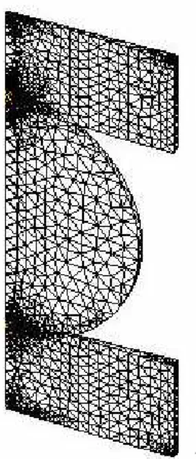
E1= 2 =21⋅1011 and Poisson coefficient, ν =0.3, pressed by a force Q=100N, as seen in Figure 5. Due to geometrical and loading symmetry, the points from any axial plane will remain in the same plane after the parts deform. Considering these, the analysis was performed on a narrow slice containing the symmetry axis, as seen in Figure 5.b. The same figure also illustrates the meshing with variable parameters, a refined meshing being applied in the contact regions.
a) b)
Fig. 5a. Sphere–plate contact model Fig. 5b. Meshing of the model
Fig. 6. Detail for finding maximum of
σ
z stressAs it can be seen from Figure 6, the maximum value of σz stress, which has to match the admissible stress, explicitly p0 =3.39GPa. A precise calculus for maximum contact pressure made using relations from contact mechanics theory, [1], leads to a value
GPa .
Fiabilitate si Durabilitate - Fiability & Durability no 2(6)/ 2010
Editura “Academica Brâncuşi” , Târgu Jiu, ISSN 1844 – 640X
82
4. The contact sphere-intermediate part-plate
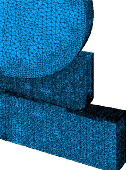
In this case, the meshing was also completed with a variable element size, the parameters of the netting being reduced in the regions with high stresses.
Fig.7. Meshing of the assembly Fig. 8. Von Mises equivalent stress
4.1. Contact on spherical surface
As it can be seen from Figure 7, on the contact region from the spherical surface there are not stress concentrators, even though the intermediate element material is highly stressed at its centre. Figure 9 presents the
σ
z stresses in this element and the von Mises equivalentstress, too.
a)
b)
Fig. 9. Stresses in intermediate element: a)
σ
z stress; b) Von Mises stress4.2. Contact on plane surface
Fiabilitate si Durabilitate - Fiability & Durability no 2(6)/ 2010
Editura “Academica Brâncuşi” , Târgu Jiu, ISSN 1844 – 640X
83
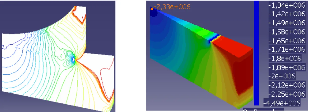
Fig. 10. Maximum of
σ
z stress on the contact surface in the intermediate part-plate assemblyOn the contact surface, the maximum of
σ
z stress is the maximum contact pressure andit takes the value 4.49MPa. In order to estimate this numerical result, the analytical
relations given by Shtaerman, [5], are applied, which refer to the calculus of contact pressure between an axially symmetrical indenter, with the profile given by a generator curve with two regions, more precise, a straight one connected to a parabolic one, as shown in Figure 11. In order to apply the relations given by Shtaerman, in the vicinity of the point of transition from straight line to parabolic profile, the parabola is replaced by its osculating circle, [6].
Allowing for the contact stresses have a strictly local effect, it is accepted the hypothesis that in the vicinity of change point from linear profile to circular profile, the circle has the same curvature radius as the parabola and the Shtaerman equations can be applied to find the contact stresses under the indenter. The problem occurring is to find the equation of the parabola having as osculating circle the same circle as the filleting circle for the profile of intermediate part. It must be found the parabola with vertical axis, with the tip in the connecting point of linear profile and having at tip the same curvature radius as the filleting radius of the intermediate part profile. The solution for this problem is presented in Figure 11.b, where there are shown together the actual profile of the intermediary part and the necessary profile used in applying Shtaerman method, and also, the osculating circle, common to both profiles. The pressure profile and its three-dimensional aspects are presented in Figure 12.
a)
b)
Fiabilitate si Durabilitate - Fiability & Durability no 2(6)/ 2010
Editura “Academica Brâncuşi” , Târgu Jiu, ISSN 1844 – 640X
84
a) b)
Fig. 12. Contact pressure under the indenter for Shtaerman’s problem
One can notice that the pressure under the indenter for Shtaerman’s problem has the minimum value in the centre of the indenter, pmin =1.7MPa, a value different compared to the numerically found pressure, of 2.33Pa and the maximum pressure has the value
MPa . ) r ( p
pmax = 0 =378 , compared to the numerically found 4.49MPa. One can conclude that the numerically found pressures are higher than the analytically found ones, but, we must remember that simplifying assumptions were made for the analytical calculus and, though, the results have the same magnitude order.
5. Conclusions
The paper presents the stresses from the wobble plate mechanism, numerically found using the finite element analysis performed in CATIA, and emphasising the most stresses regions of the mechanism. The mechanism was considered for two design solutions: first, considering the Hertzian contact between the plate and the plunger and for the second case, an equivalent variant presenting a newly introduced element aiming to reduce the contact stresses. For both cases the contact pressure was evaluated using analytical methods in order to estimate the accuracy of numerical method. For the first mechanism, the maximum Hertzian pressure was found and for the second one, it was estimated the contact pressure between the intermediate part and the swash plate. For both cases, the numerical results exceeded the analytical values. For the analytical calculus, simplifying assumptions were made and yet, the results are validated by the numerical ones. The main conclusion traced is that the numerical methods applied for stress and strain state evaluation are extremely efficient but the results must be cautiously analyzed. In the zones presenting high stress gradients, leading to stress concentrators, it is recommended to proceed in order to diminish these. The most common operation is increasing the curvature radii of the elements in the closed neighborhood zones where the elements are contacting.
References
[1] Johnson, K. L., Contact Mechanics, Cambridge University Press, 1985;
[2] Timoshenko S. P., Goodier, J.N., Theory of Elasticity, McGraw Hill; 3rd edition (October 1, 1970);
[3] Zienkiewicz O.C., Taylor, R.L., The Finite Element Method for Solid and Structural Mechanics, Butterworth-Heinemann, 2005;
[4] Fisher, I, Dual Number Methods in Kinematics, Statics and Dynamics, CRC Press, 1999; [5] Shtaerman, M, Contact Problems in the Theory of Elasticity, in Russian, Gostehizdat, Moskow, 1949;