© 2012 WIT Press, www.witpress.com
ISSN: 2041-9031 (paper format), ISSN: 2041-904X (online), http://journals.witpress.com DOI: 10.2495/SAFE-V2-N3-242-255
STRUCTURAL SAFETY IN WOODEN BEAMS UNDER
THERMAL AND MECHANICAL LOADING CONDITIONS
E.M.M. FONSECA, D.C.S. COELHO & L.M.S. BARREIRA Department of Applied Mechanics, Polytechnic Institute of Bragança, Portugal.
ABSTRACT
The main objective of this paper is to identify different analytical methods which permit the calcula-tion of the stress level in wooden simply supported beams, due to mechanical and thermal loading conditions. Two different wood species, with different cross-sections, will be presented. The fi re resistance, the charring depth layer and the charring rate will be determined using the fi nite element method with Ansys® program. To characterize the stress state in wooden beams, all elements are subjected to mechanical load considering the reduction of the cross-section, infl uenced by thermal action. Another purpose of this work is to identify the ultimate safe load-bearing capacity in wooden beams, subjected to uniform load simultaneously with the thermal effect. All numerical results per-mit the specifi cation of simple design calculation methods, simplifying the verifi cation of the fi re safety of wooden beams.
© 2012 WIT Press, www.witpress.com
ISSN: 2041-9031 (paper format), ISSN: 2041-904X (online), http://journals.witpress.com DOI: 10.2495/SAFE-V0-N0-1-14
STRUCTURAL SAFETY IN WOODEN BEAMS UNDER
THERMAL AND MECHANICAL LOADING CONDITIONS
E.M.M. FONSECA, D.C.S. COELHO & L.M.S. BARREIRA Department of Applied Mechanics, Polytechnic Institute of Bragança, Portugal.
ABSTRACT
The main objective of this paper is to identify different analytical methods which permit the calcula-tion of the stress level in wooden simply supported beams, due to mechanical and thermal loading conditions. Two different wood species, with different cross-sections, will be presented. The fi re resistance, the charring depth layer and the charring rate will be determined using the fi nite element method with Ansys® program. To characterize the stress state in wooden beams, all elements are subjected to mechanical load considering the reduction of the cross-section, infl uenced by thermal action. Another purpose of this work is to identify the ultimate safe load-bearing capacity in wooden beams, subjected to uniform load simultaneously with the thermal effect. All numerical results per-mit the specifi cation of simple design calculation methods, simplifying the verifi cation of the fi re safety of wooden beams.
Keywords: charring depth, fi re, load-bearing capacity, uniform load, wooden beam.
1 INTRODUCTION
Wood is a renewable resource, recently attracting public attention, as an environmentally friendly material. This product is a building material with attractive attributes such as archi-tectural and structural characteristics. Wood is classifi ed in two different botanical terms. The botanical terms, softwoods and hardwoods, indicate the basic structure and cell type of mois-ture within the tree. Softwoods generally come from the coniferous species (pines, fi rs and spruces, for example) and are generally fi ne textured. Hardwoods (eucalypts and oaks, for example) have broad leaves and the texture ranges from fi ne to coarse. The types of wood include softwoods, hardwoods and glued laminated woods, in the forms of solid wood, ply-wood and ply-wood-based panels. Due to large variation, type and ply-wood quality, a system of strength classes was established. Each grade of classifi cation is a function of the physical and wood properties. The wood when exposed to accidental actions, such as fi re conditions, pre-sents a surrounding charring layer. However, this layer can delay the heating process from the exposed side to the wood core section, acting as an insulating layer. The wood core section may remain at low temperatures, depending on the fi re exposure and element size therefore. It is important to calculate the value of charring rate and determine the thickness of char layer formation through the section. These parameters are important in fi re safety design because they determine the residual load-bearing cross-section, due to critical external conditions. Safety rules and guidelines should be useful for different wooden structures. The high vulner-ability of wood, with respect to fi re, requires a rigorous thermal and mechanical analysis. The study of fi re resistance of wood structures is therefore a topic of great interest. Several researchers have presented experimental and numerical models for the study of wood in the presence of high temperatures [1–3]. The charring rate of softwood or hardwood material, exposed to fi re conditions, has been studied in different countries, [4–11]. Some empirical models for charring rate calculation have been developed by other researchers [4–6].
production and applicable to engineering construction in general, being used as structural elements such as beams or columns, or in lamellar form.
This work describes the fi re performance in structural wooden beams. It intends to compile design formulas for further discussions and enhancements to structural safety of wooden beams under thermal and mechanical loading conditions. The authors of this work have pub-lished different articles in conferences and journals related to this theme [12–15]. They studied other wood species to analyze the evolution of charring rate using experimental and numerical methods.
The main objectives of this work are:
•
Evaluate the thermal and mechanical performance of wood, when subjected to elevated temperatures due to the simulation of a fi re situation;•
Present simulation models for the analysis of the behavior of typical cross-sections when subjected to the presence of fi re;•
Determine the charring layer of two different species of wood;•
Determine the mechanical resistance in a wide range of selected profi les and installed stresses arising on the basis of the residual cross-section;•
Present a set of simple calculation methods for simply supported beams, under the effect of a distributed load, considering the residual cross-section;•
Determine the ultimate load-bearing capacity of simply supported beams, as a function of load level.2 STRENGHT OF WOOD AT HIGH TEMPERATURES
The most important factors for the calculation of the structural strength in wooden elements subjected to fi re are the thermal degradation and the charring depth formation. The wood density decreases with the material degradation caused by the pyrolysis process, in the pres-ence of high temperatures. The pyrolysis process usually starts for wood temperatures of 280 ºC to 300 ºC, [16]. The charred area has no effective resistance, producing a reduction in the resistance of the effective cross-section. On the other hand, the charring depth depends on the time of fi re exposure. The verifi cation of these parameters contributes to the assessment of their load-bearing capacity. Wood exhibits an exceptional load-bearing capacity under fi re when compared with other traditional materials, such as steel and concrete. Not including the connections in the structure, where the protection at high temperatures should have particular attention, a proper cross-section size in wooden elements ensures the stabilization time to fi re, without demanding special protection systems. According to Eurocode 1 (2002) [17], the evolution of fi re temperature over time may be defi ned by standard fi re curves. In this work the standard ISO834 fi re curve was adopted.
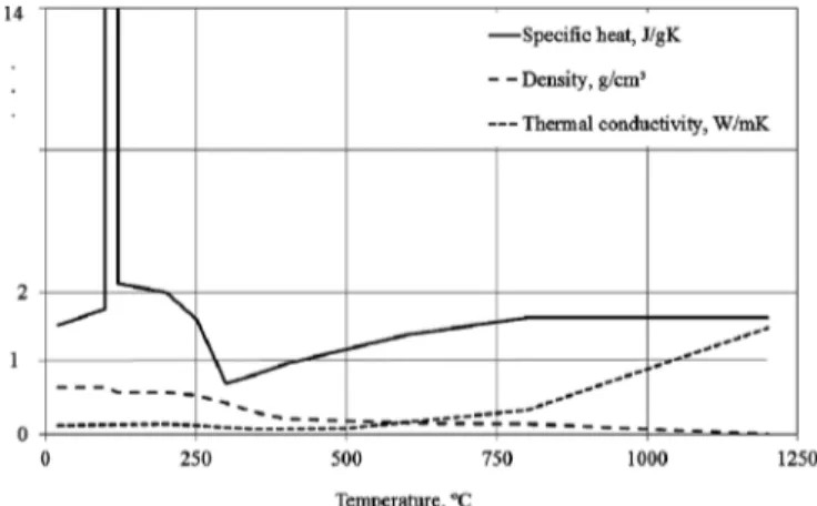
2.1 Thermal and mechanical properties
heat. The values below 350 ºC represent the properties of wood, and above 350 ºC represent the properties of charred layer. The wood species considered in this study are Fir subalpine and Redwood and the value of density is equal to 460 kg/m3 and 520 kg/m3, respectively.
Wood is a complex composite material and is generally anisotropic, heterogeneous and porous. Mechanical properties depend upon grain orientation, and are also affected by mois-ture content, [19]. The mechanical behavior of wood varies with temperamois-ture when subjected to an accidental situation, as is the case of a fi re. The increase of temperature infl uences the progressive degradation of mechanical material properties. Apart from reducing of the cross-section, the degradation of mechanical properties contributes to the loss of structural-bearing capacity. The Eurocode 5 (2003) considers a reduction of mechanical properties in the order of 20% compared to the same material at room temperature. Wood may be described as an orthotropic material, with their mechanical properties described relative to the three mutually orthogonal axes: longitudinal, radial and tangential, infl uenced by grain direction [16, 19, 20]. The longitudinal axis L is parallel to the wood fi ber, the radial axis R is normal to the growth rings, and the tangential axis T is perpendicular to the grain but tangent to the growth rings, [20]. The material was considered with moisture content level to 12% and the mechanical properties are presented in Table 1 [1]. The three moduli of elas-ticity, which are denoted by EL, ER and ET, respectively, are the elastic moduli along the longitudinal, radial and tangential axes of wood; three moduli of rigidity, GLR, GLT and GRT in the LR, LT and RT planes; and Poisson’s ratios in the same planes, where the fi rst letter of the subscript refers to direction of applied stress and the second refers to the direction of lateral deformation, [20].
Figure 1: Thermal properties of wood elements.
Table 1: Mechanical properties and elastic ratios for two species [20].
Species
σmáx
MPa EL
MPa ET/EL ER/EL GLR/ELGLT/ELGRT/EL µLR µLT µRT
Fir subalpine 40.00 10300 0.039 0.102 0.070 0.058 0.006 0.341 0.332 0.437
The mechanical properties of wood are affected by the temperature. The orthotropic proper-ties are determined according to the temperature-dependent reduction factor K in Eurocode 5 (2003), Tables 2 and 3.
The mechanical strength of both species is defi ned in Table 3 according to Eurocode 5 (2003). The strength decreases faster for temperatures up to 100 ºC and decreases slowly for temperature between 100 ºC and 300 ºC.
The coeffi cient of thermal expansion is a measure of the relative change of dimension caused by temperature change and is infl uenced by the orientation of the grain. In tests of both hardwoods and softwoods, the parallel-to-grain values have ranged from about 3.1 to 4.5 × 10⁻⁶ ºC−1 and from 21.6 to 39.4 × 10⁻⁶ ºC−1 across the grain, [16]. In this work a value of thermal expansion equal to 3.1 × 10⁻⁶ ºC−1 was considered, [19].
3 CASE STUDIES
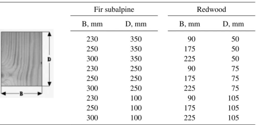
This study considers two species of softwood, origin of northern Europe and marketed in Portugal: Fir subalpine and Redwood. To standardize the characteristics of these woods, dif-ferent datasheets of several companies have been consulted. Table 4 shows the main standard dimensions considered in this work, where B is the initial breadth and D is the member depth.
3.1 Thermal resistance of wooden sections
A nonlinear and transient thermal analysis was carried out using the general purpose fi nite element software Ansys®. A two-dimensional fi nite element with eight nodes (PLANE77)
Table 2: Moduli of elasticity and rigidity as functions of temperature [20].
Species T, ºC K
Moduli of elasticity, MPa Moduli of rigidity, MPa
EL ET ER GLR GLT GRT
Fir subalpine
20 1.00 10300 401.7 1050.6 721 597.4 61.8
100 0.50 5150 200.85 525.3 360.5 298.7 30.9
300 0.01 103 4.02 10.51 7.21 5.97 0.62
Redwood
20 1.00 9200 818.8 800.4 607.2 708.4 101.2
100 0.50 4600 409.4 400.2 303.6 354.2 50.6
300 0.01 92 8.19 8 6.07 7.08 1.01
Table 3: Maximum tensile and compressive strength [18].
Species T, ºC K
Compressive σmax (T), MPa
Tensile σmax (T), MPa
Fir subalpine
20 1.00 40.00 68.00
100 0.50 20.00 34.00
300 0.01 0.40 0.68
Redwood
20 1.00 42.40 69.00
100 0.50 21.20 34.50
was used. All cross-sections considered in Table 4 were modeled and 36 simulations were performed, with fi re exposure on three or four sides.
The time history of the temperature fi eld was calculated during one hour of fi re exposure. One objective is to determine the char layer thickness versus time for different sections exposed to fi re. The boundary conditions considered in all analysis were convection and radiation, according to the temperature evolution in fi re. The evolution of fi re temperature over time was defi ned by standard fi re curve ISO834. The convection coeffi cient used for surfaces directly exposed to fi re was considered equal to 25 W/m2K, according to Eurocode 1 (2002). Eurocode 5 (2003) proposes the value of emissivity in wood material equal to 0.8. The charring layer thickness is determined by the results obtained through monitoring and recording the temperature threshold value of 300 °C. The boundary layer that limits the wood cold core was defi ned according to Eurocode 5 (2003).
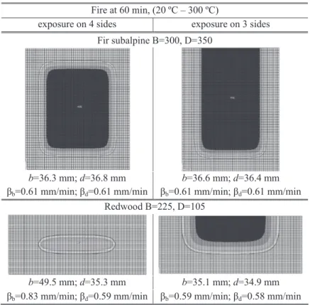
The following images in Fig. 2 present the numerical results associated with the tempera-ture profi les in the range from 20 °C to 300 °C; the thickness of the layer which is the ash is the depth carbonized, in which there were temperature records above 300 ºC. The charring depth layer thickness is represented by (b) in the tangential direction and (d) in the vertical direction. The calculation of the charring rate, results from the ratio of charring depth to the time of fi re exposure, represented through βb and βd, respectively in Fig. 2.
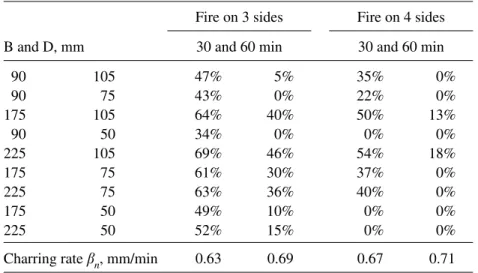
The charring rate and the residual area after fi re exposure were determined. The average of charring rate βn was calculated for each studied profi le based on values of βb and βd. The residual wood cross-section for each standard size B × D was obtained for different time of fi re exposure, as represented in Tables 5 and 6. The residual area (Ar) was obtained as the difference between the initial cross-section and the charring depth effect, and it is represented as a percentage of the initial cross-section area (A). Based on all numerical results for calcu-lating the charring depth, the average charring rate bn for each fi re exposure was determined, as represented in Tables 5 and 6.
The typical values for charring rate of wood varies between 0.5 and 1.0 mm/min. Eurocode 5 (2003) allows the use of simplifi ed and advanced methods for the calculation of the amount of charring depth layer. This method is a conduction model based on thermal properties of wood. According to Eurocode 5 (2003), the proposed formula to calculate the
Table 4: Different standard sizes.
Fir subalpine Redwood
B, mm D, mm B, mm D, mm
230 350 90 50
250 350 175 50
300 350 225 50
230 250 90 75
250 250 175 75
300 250 225 75
230 100 90 105
250 100 175 105
Figure 2: Mesh of the cross-section and thermal numerical results.
Table 5: Residual area (Ar = %A), Fir subalpine.
B and D, mm
Fire on 3 sides Fire on 4 sides
30 and 60 min 30 and 60 min
230 350 78% 61% 74% 54%
250 350 80% 63% 75% 55%
300 350 82% 68% 77% 60%
230 250 77% 58% 70% 48%
250 250 78% 60% 71% 49%
300 250 80% 64% 74% 53%
230 100 66% 42% 49% 10%
250 100 68% 44% 50% 11%
300 100 70% 47% 52% 13%
charring depth, when exposure to fi re is in more than one direction, depends on the charring rate used for unprotected surfaces, according to:
b =
,
char n n
d t (1)
where dchar,n is the charring depth layer in mm, βn is the design charring rate under standard fi re exposure in mm/min and t is the time of fi re exposure in min.
Table 7 compares the obtained numerical charring rate with a constant value proposed by Eurocode 5 (2003). The obtained charring rate is higher when fi re exposure is on four sides and for Redwood species.
Eqn (2) should be used for the calculation of the effective charring depth layer, according to Eurocode 5 (2003):
k = , + ×7 0, mm
ef char n
d d (2)
where k0 is a function of the duration of fi re exposure. For unprotected surfaces, and time exposure less than 20 min, k0 = 1; when time is greater and equal to 20 min, k0 is equal to
k0 = t/20.
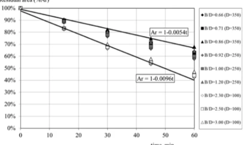
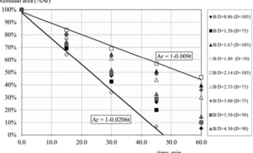
Figures 3, 4, 5, 6 represent different graphs, with an original formula, which permit the determination of the residual area (%Ar) due time exposure (t, min) in all wood species
Table 6: Residual area (Ar = %A), Redwood.
B and D, mm
Fire on 3 sides Fire on 4 sides
30 and 60 min 30 and 60 min
90 105 47% 5% 35% 0%
90 75 43% 0% 22% 0%
175 105 64% 40% 50% 13%
90 50 34% 0% 0% 0%
225 105 69% 46% 54% 18%
175 75 61% 30% 37% 0%
225 75 63% 36% 40% 0%
175 50 49% 10% 0% 0%
225 50 52% 15% 0% 0%
Charring rate bn, mm/min 0.63 0.69 0.67 0.71
Table 7: Comparison of charring rate bn mm/min.
Species
Ansys®
Eurocode 5 (2003) Fire exposure on 3 sides Fire exposure on 4 sides
Fir subalpine 0.64 0.68 0.65
considered in Table 4. In all graphs a linear tendency line was obtained according to the maximum and the minimal values represented.
The studied profi les in Fig. 3 present a resistant area greater than 40% when exposed to fi re on three sides.
In Fig. 4 when fi re exposure increases, the resistant area decreases. For the same time of fi re exposure the slender profi les have less strength.
Some of Redwood profi les were able to resist only 45 min of fi re exposure, when exposed to three sides.
The fi re exposure of Redwood species on four sides is more critical. After 30 min of fi re exposure, all profi les have a reduction greater than 50% of the resistant cross-section. Cross-sections in Redwood have less resistance when compared with Fir subalpine. Fir subalpine has a cross-section which resists for one hour of fi re exposure on three sides, with a residual
Figure 3: Fire exposure on three sides, Fir subalpine.
area around 70%. In all profi les the residual area on three sides is comparatively higher to fi re exposure on four sides.
3.2 Thermal and mechanical resistance in wooden beams
A structural and linear fi nite element analysis using temperature data from thermal analysis was used to study different wooden beams, simply supported and subjected to a uniform loading, as shown in Fig. 7. Three-dimensional fi nite solid elements (SOLID185) with eight nodes were used in Ansys® program for the mechanical analysis. The total length of the wooden beam is equal to 3 m and the value of the uniform load is equal to 0.5 kN/m.
Longitudinal maximum stresses were calculated in all beam elements using orthotropic material properties. Figure 8 shows the numerical results obtained for two different species
Figure 5: Fire exposure on three sides, Redwood.
of wooden beams. The fi rst column represents the resistant area obtained for 60 min of fi re exposure. The second and third columns represent the maximum and minimum stress at mid cross-section of the wooden beam, as the result of the thermal and mechanical loading combination.
The longitudinal stress distribution is linear through the cold section, but decreases quickly in the charring layer. For three sides of fi re exposure, the neutral axis diverges from the original position, by about a value equal to one half of the charring depth. For this condition, the maximum longitudinal stress occurs due to compression. When fi re exposure is on four sides, the neutral axis remains unchangeable. Analytical and standard formula were provided
Figure 7: Solid mesh for the simply supported beam.
for the bending stress calculation in wooden beams, simply supported with fi re exposure in three or four sides and a uniform load. In these equations the moment of inertia is affected by the charring depth layer, reducing the initial cross-section size of the beam. Analytical equa-tions could be used to further the progress and validation of computational modeling tools in predicting the fi re performance of wood-based constructions.
3.3 Structural safety in wooden beams
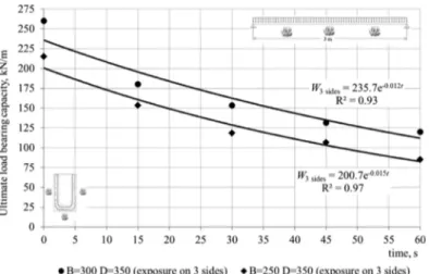
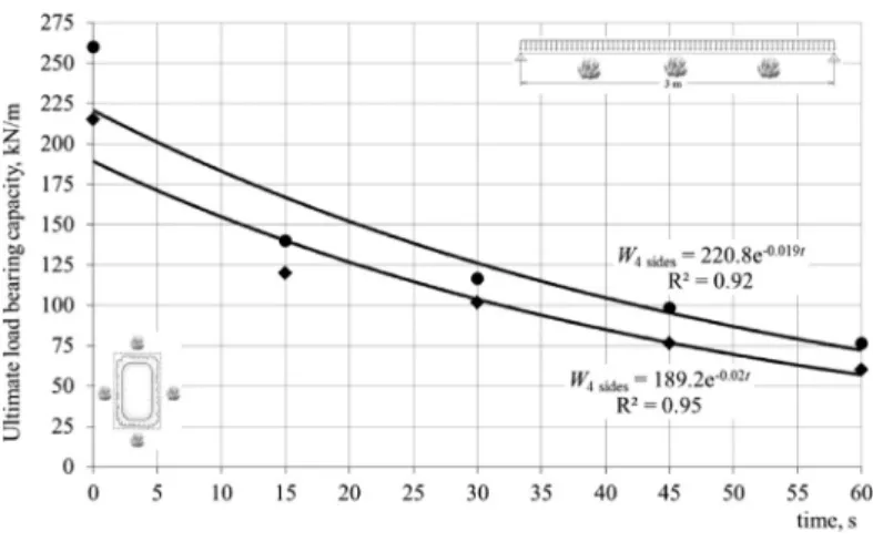
For assessing the safety of wooden beams, a structural nonlinear fi nite element analysis was implemented, using temperature data from thermal analysis and an incremental and iterative solution method. The same three-dimensional fi nite solid element (SOLID185) was used with eight nodes and three degrees of freedom at each node. Various plots were obtained with the value of the ultimate load-bearing capacity (W), as shown in Figs. 9–12. All curves are functions of fi re exposure time during one hour for wooden beams considering fi re on three or four sides. For each fi re condition an exponential regression was obtained which permits the calculation of ultimate uniform load-bearing capacity in wooden beams subjected to fi re conditions, in three or four sides. In these graphs the solution is presented for two different cross-sections (B = 250 D = 350; B = 300 D = 350) and (B = 175 D = 105; B = 225 D = 105) for Fir subalpine and Redwood species, respectively. In this study, the selected cross-sections present higher fi re resistance, as presented in Tables 5 and 6.
Figures 9 and 10 represent the ultimate uniform load-bearing capacity for Fir subalpine. The ultimate load-bearing capacity of this wooden specie is higher for three sides of fi re exposure in comparison to four sides. All graphs represent different exponential formulas which permit the calculation of the load-bearing capacity in different time instants.
Figures 11 and 12 represent the solution for the ultimate load-bearing capacity for Red-wood. All cross-sections studied are less fi re resistant than Fir subalpine. As shown, the ultimate load-bearing capacity is around 10 times less than that for the same cross-sections in Fir subalpine.
The assessment of the ultimate load bearing in fi re condition is presented for both species. Failure can occur when the full strength cold core sections are no longer capable of support-ing the load. Simple analytical formulas are presented to determine the ultimate load-bearsupport-ing capacity (3) and 4. These formulas should be used for future recommendations in wooden beams simply supported and exposed to fi re, function of mechanical strength and residual section area.
s × − −
=
×
2 max( )
3 2
4( 2 )( )
3
T ef ef
ultimate load bearing exposure on sides
B d D d
W
L (3)
s × − −
=
×
2 max( )
4 2
4( 2 )( 2 ) 3
T ef ef
ultimate load bearing exposure on sides
B d D d
W
L (4)
Figure 10: Ultimate load-bearing capacity for fi re exposure on four sides, Fir subalpine.
where W is the ultimate uniform load bearing, σmax(T ) is the maximum strength of the wood material at a fi re temperature, L is the effective length of beam, B is the breadth of member before exposure to fi re, D is the depth of member before exposure to fi re and def is the charring depth.
Also the obtained numerical results agree with the values derived from these formulas. Using the simple calculation method (formulas (3) and (4) to wooden beams) it was found that the imposed maximum distributed load, decreases with decreasing the resistance of the profi le cross-section under the thermal effect. After one hour of fi re exposure, Fir subalpine species suffers a reduction of 50% in the ultimate load-bearing capacity. For Redwood, the behavior is more critical, since all studied cross-sections hardly withstand any mechanical load when exposed to fi re for one hour.
4 CONCLUSIONS AND FUTURE WORK
In this work the structural fi re performance of wooden beams was estimated using the fi nite element method. The cross-sections made of Fir subalpine present higher fi re resistance than Redwood species. High temperatures reduce the dimensions of wood cross-sections, as the strength and the stiffness of the heated affected zone. The stress decreases quickly in the char-ring layer. When fi re exposure is on three sides, neutral axis diverges from the original position but remains unchangeable with fi re on four sides. Wood exposed to fi re will decom-pose to provide an insulating charred layer that retards further degradation.
In this work, simple design formulas were presented to facilitate the assessment of fi re resistance and the resistant area of simply supported wood beams. These formulas could be used to verify the proper cross-section size in wooden elements that ensures a stabilization time to fi re, without demanding special protection systems.
Future developments in this area should consider the experimental validation, perform the same study for other type of loading and supporting conditions, study the behavior of wood in tubular sections subjected to the fi re action and study the behavior of wood protected with insulation material.
REFERENCES
[2] Poon, L. & England, J.P., Literature Review on the Contribution of Fire Resistant Timber
Construction to Heat Release Rate – Timber Development Association, Warrington
Fire Research Aust. Pty. Ltd., Project No.20633, version 2b, pp. 1–78, 2003.
[3] Janssens, M.L., Modeling of the thermal degradation of structural wood members exposed to fi re. Fire and Materials, 28, pp. 199–207, 2004.
[4] Schaffer, E.L., Charring Rate of Selected Woods Transverse to Grain. Research paper FPL 69 Forest Products Laboratory: Madison (WI), 1967.
[5] White, R.H., Charring Rates of Different Wood Species. PhD dissertation, Madison University of Wisconsin, Madison (WI), 1988.
[6] White, R.H., Erik, V. & Nordheim, E.V., Charring rate of wood for ASTM E119 expo-sure. Fire Technol, 28(1), 1992.
[7] Konig, J. & Walleij, L., One-Dimensional Charring of Timber Exposed to Standard and Parametric Fires in Initially Unprotected and Postprotection Situations. Swed Inst Wood Technol Res, 1999.
[8] Gardner W.D. & Syme, D.R. Charring of Glued-Laminated Beams of Eight Australian-Grown Timber Species and the Effect of 13 mm Gypsum Plasterboard Protection on their Charring. N.S.W. Technical report no.5, Sydney, 1991.
[9] Collier, P.C.R., Charring Rates of Timber, Study report, Branz: New Zealand, 1992. [10] Pun, C.Y., Seng, H.K., Midon, M.S. & Malik, A.R., Timber Design Handbook. FRIM,
Malayan Forest Records no.42, 1997.
[11] Cachim, P.B. & Franssen, J.M., Assessment of Eurocode 5 charring rate calculation methods. Fire Technology, 46, pp. 169–181, 2010.
[12] Fonseca, E.M.M. & Barreira, L., Charring rate determination of wood pine profi les submitted to high temperatures. Third International Conference on Safety and Security Engineering, Vol. 108, eds M. Guarascio, C.A. Brebbia, F. Garzia, WIT Press: Italy, pp. 449–457, 2009.
[13] Fonseca, E.M.M. & Barreira, L.M.S., Metodo experimental para determinacao da espessura carbonizada na madeira quando submetida a altas temperaturas. Revista Por-tuguesa de Engenharia de Estruturas RPEE, 7, pp. 33–40, 2010.
[14] Fonseca, E.M.M. & Barreira, L., High temperatures in parallel or perpendicular wood grain direction: a numerical and experimental study. WIT Press, Fourth International Conference on Safety and Security Engineering IV, eds. M. Guarascio, G. Reniers, C.A. Brebbia, F. Garzia, Belgium, 117, pp. 171–183, 2011.
[15] Fonseca, E.M.M. & Barreira, L., Experimental and numerical method for determining wood char-layer at high temperatures due an anaerobic heating. International Journal of Safety and Security Engineering, 1(1), pp. 65–76, 2011.
[16] Gandhi, PD. & Backstrom, R., Thermal and Mechanical Finite element modelling of
Wood-Floor Assemblies Subjected to Furnace Exposure. Project number: 07CA42520,
Underwriters Laboratoires, USA, 2008.
[17] EN 1991-1-2:2002. Eurocode 1: Actions on Structures – Part 1–2: General actions – Actions on Structures Exposed to Fire, CEN, 2002.
[18] EN 1995-1-2:2004. Eurocode 5: Design of timber structures, Part 1–2: General- Structural fi re design, CEN, 2004.
[19] Winady, J. & Rowell, R., Chapter 11. Chemistry of Wood Strength. Handbook of Wood
Chemistry and Wood Composites, CRC Press LLC, 2005.
[20] Green, D.W., Winandy, J.E. & Kretschmann, D.E., Mechanical Properties of Wood,
ch04, Wood Handbook Wood as an Engineering Material, Forest Products Laboratory
![Table 2: Moduli of elasticity and rigidity as functions of temperature [20].](https://thumb-eu.123doks.com/thumbv2/123dok_br/17001203.764418/5.744.103.652.138.322/table-moduli-elasticity-rigidity-functions-temperature.webp)