NUMERICAL STUDY OF TURBULENT NORMAL DIFFUSION FLAME
CH
4-AIR STABILIZED BY COAXIAL BURNER
by
Zouhair RIAHIa*, Mohamed Ali MERGHENIc*, Jean-Charles SAUTETb, and Sassi BEN NASRALLAHc
aCentre of Research and Technology of Energy, LMEEVED, Borj Cedria, Hammam-Lif, Tunisia bCORIA UMR 6614 CNRS – University and INSA ROUEN, Saint Etienne of Rouvray, France
cNational School of Engineering Monastir, LESTE, Monastir, Tunisie
Original scientific paper DOI: 10.2298/TSCI110609042R
The practical combustion systems such as combustion furnaces, gas turbine, en-gines, etc., employ non-premixed combustion due to its better flame stability, safety, and wide operating range as compared to premixed combustion. The present nu-merical study characterizes the turbulent flame of methane-air in a coaxial burner in order to determine the effect of airflow on the distribution of temperature, on gas consumption, and on the emission of NOx. The results in this study are obtained by simulation on FLUENT code. The results demonstrate the influence of different pa-rameters on the flame structure, temperature distribution and gas emissions, such as turbulence, fuel jet velocity, air jet velocity, equivalence ratio, and mixture frac-tion. The lift-off height for a fixed fuel jet velocity is observed to increase monotonically with air jet velocity. Temperature and NOxemission decrease of im-portant values with the equivalence ratio, it is maximum about the unity.
Key words: non-premixed combustion, coaxial burner, turbulent flame, lift-off height, equivalence ratio, mixture fraction, NOxemission Introduction
Generally, there are three main types of the flame: the premixed flame, diffusion flame (non-premixed flame), and partially premixed flame. The diffusion flame used in the most in-dustrial applications, such as inin-dustrial furnaces, diesel engines, aeronautics (rocket engine),
etc. due to its better flame stability and safety as compared to premixed combustion. In this pro-cess fuel and oxidizer are injected into the flame by two streams, one for gas other for air or oxy-gen. The two different configurations of the diffusion flame are: normal diffusion flame (NDF), in a simple coaxial burner, the central gas jet enveloped by annular air jet. Inverse diffusion flame (IDF) is a kind of flame with an inner air jet is surrounded by outer fuel jet. The research of non-premixed combustion started in 1928 by Burke and Schumann on the flame properties such flame length, lift-off from the burner, temperature, and mass fractions of combustion products. These properties depend upon mixture fraction. The principal objectives of the research in the field of non-premixed combustion are: reducing atmospheric pollution and maintain a more sta-ble flame, therefore a good performance of combustion system. The principal objectives of the research in the field of non-premixed combustion are: the reduction of atmospheric pollution and the improvement of flame stability, therefore a good performance of combustion system.
Several researchers reported the effect of air-fuel velocity ratio on the characteristics of NDF and IDF. The first detailed investigation was performed by Mahesh and Mishra [1, 2] for experimental study characterizing the turbulent liquefied petroleum gas (LPG) for inverse diffu-sion flame stabilized in a back-step burner in terms of visible flame length, dual flame structure, centerline temperature distribution and oxygen concentration. Sze,et al. [3] carried out experi-ments on the appearance, temperature distribution, and NOxemission of two inverse diffusion flames, one with circumferentially arranged ports and the other with co-axial jets, both burning liquefied petroleum gas. Sobiesiak and Wenzell [4] reported the effect of air and fuel jet diame-ters and the ratio of inner air jet and outer fuel jet velocities on temperature distribution, flame length, and stability limits on inverse diffusion flame. Fernandezet al. [5] carried the numerical study of Liftoff and blow out of methane jet diffusion flame between parallel streams of meth-ane diluted with nitrogen and air. Santos and Costa [6] characterized jet diffusion flames for three fuels such as methane, ethylene, and propane gases experimentally in terms of flame lift-off height, flame length, and NOxemission. Meunieret al. [7] investigated on NOxemissions from turbulent propane diffusion flames. The study includes both experimental measurements and numerical 2-D simulations and aims to provide a better understanding of the dominant phys-ical effects associated with the NOxproduction in turbulent diffusion flames. Montgomeryet al. [8] reported the effect of co-flow velocity on a lifted methane-air jet diffusion flame. The lift-off height increases with jet exit velocity and with the air co-flow velocity. Many researchers [9-14] carried experimental and numerical out the effect of hydrogen jet on stability, distribution of temperature, and NOxemission. Ohet al. [9, 13] investigated the effect of nitrogen dilution and acoustic excitation on the stabilization and NOxemission of turbulent diffusion flames. They concluded that the turbulent flame propagation velocity increased as the mole fraction of nitro-gen diluents gas decreased. However, the dilution of nitronitro-gen is characterized by lower mixture fraction and reduced burning velocity. This premixing effect resulted in a lower flame tempera-ture and lower NOxproduction. Flame length decreased with acoustic excitation, NOxemission was reduced and minimized at a resonance frequency. Mishra and Kumar [10, 11] investigated the effect of H2addition on the flame length, soot free length fraction, radiant fraction, gas tem-perature, and emission NOxin the LPG composed of 69% C3H8and 30% C4H10jet diffusion flame. El-Ghafour [12] performed an experimental investigation on turbulent natural gas-hy-drogen jet diffusion flame and observed the effect of hygas-hy-drogen addition on flame stability, flame length, flame structure, exhaust species concentration and pollutant emissions. Other experi-mental studies [15-17] on the characteristics of high temperature diluted air combustion showed that it yields very low NOxemission, low luminosity, higher flame stability, large flame volume and a more uniform temperature. Several studies reported the control of the flame by inclined oxygen jets [18-20]. This idea enhanced the premixed fuel-oxidant, therefore reduces emission of NOx.
In this context, the present work provides a numerical investigation of the turbulent methane-air jet in a coaxial burner. The aim is to examinine the effects of air jet velocity on the flame stability, distribution of temperature, and gas emission with fixed fuel jet velocity.
Numerical modeling
Mathematical formulation
mean velocity of 10 m/s. This leads to a fuel exit Reynolds number of 5217. The stoichiometric mixture fractionxis 0.055. Through a surrounding nozzle having diameter of 18 mm, air is injected with different velocities, fig. 1. The modelisa- tion of this configuration is obtained by FLUENT. We used thek-eturbulent model. The cal-culations have been performed in axisymmetric co-ordinates (x, y), 250 mm forxand 1000 mm fory.
The numerical model solves the independent time equa-tions for conservation of mass, momentum, energy, and
individ-ual species: r r
Ñ(rV)=0 (1)
r r r r
Ñ(rVV)= -Ñ + ÑP ( )t +rg (2)
r¶ r
¶ ¶ ¶ h t h P
t P j q
+ VrÑ = + Ñ - ÑVr q + r (3)
rV YÑ t - ÑrD YÑ t =wt (4)
x= + & & & m m m 1 1 2 (5)
Here, the stress tensor, heat fluxjqand diffusive fluxjiare defined as:
t=m[(Ñ + Ñ )- Ñ ]
r r r
V VT 2 VI
3 (6)
j T h ji i
i n
q = - Ñ + å
= l
1
(7)
ji = -rDiÑYi (8)
The heat radiationqris defined by:
qr p a T T
i n
= - å
-=
4 4 4
1
s ( i p,i)( )
amb (9)
wheresis the Stefan-Boltzmann constant andpithe partial pressure of speciesi,ap,i– the Plank mean absorption coefficients for radiating speciesi[21],P– the static pressure, g – the term of gravity,Yi– the mass fraction,Di– the thermal diffusivity,T– the temperature, r– the density,
h– the specific enthalpy,wi– the chemical production rate,mi– the mass flux of fuel and air, and
x– the mixture fraction.
To complete the problem formulation, one needs to provide an expression for the methane consumption rate. Here, we shall consider an overall irreversible reaction where the gas reacts with the air to produce combustion products and heat according to:
CH4 +95238 021. ( . O2 +0 79. N2)®CO2 +2H O2 +75238. N2 +Q (10)
Turbulence modeling
Thek-eturbulence model presented by Launder and Spalding [22] is used to model the turbulent kinetic energykand the dissipation rate of kinetic energye. The transport equations forkandeexpressed by:
Ñ = Ñæ +
è
çç ö
ø
÷÷Ñ + -
-(r ) m m
s re
Vk t k P Dt
k
k (11)
and
Ñ = Ñæ +
è
çç ö
ø
÷÷Ñ +
-(r e) m m
s e e re e e e V C
k P C k
t
k
1 2
2
(12)
where m r
e
m
t = C
k2
(13)
For the ideal gas Dt k
T
=2r e
gR (14)
The constants:Ce1 = 1.44;Ce2 = 1.92,sk= 1;se= 1.3, andCµ= 0.09.Pkrepresents the genera-tion of the kinetic energy caused by velocity gradient and volume forces.
Combustion modeling
For the combustion reaction model, we will use the generalized finite-rate chemistry model to analyze the methane-air combustion system. The combustion will be modeled using a global one-step reaction mechanism as depicted the eq. (15):
CH4 +95238 021. ( . O2 +0 79. N2)®CO2 +2H O2 +75238. N2 (15)
The eddy dissipation model is applied to model the heat release and also to take into account the turbulence-reaction interactions. The eddy-dissipation model computes the rate of reaction under the assumption that chemical kinetics are fast compared to the rate at which reac-tants are mixed by turbulent fluctuation. In the flame zone, the eddy dissipation rate is generally smaller than the Arrhenius rate, and reactions are limited by the extent of mixing. Based on the assumption that the reaction rate is limited by both the mixing of the reactants and the heating of the reactants through the mixing with hot reaction products, the net rate of production of species
idue to reaction,Ri, is given by the smaller of the reactant mixing rate and product mixing rate [23]:
R M A
k
Y
M M AB
i i w i R R
R w R
i w i
= ¢ ¢ æ è ç ç ö ø ÷ ÷ ¢
min , min ,
,
,
n re
n n r
e k PY M P j N
j w j
å å ¢¢ é ë ê ê ù û ú ú
n , (16)
whereAandBare model constants (A= 4 andB= 0.5),n¢iandn¢¢j are the stoichiometric coeffi-cient for reactantiand productjin reaction,Mwis the molecular weight,YRandYPare mass frac-tion of any reactant and product species, respectively.
CFD modeling
Discretization procedure
Computational domain and boundary conditions
The axisymmetric computational domain (half of the flame) was extended 100 cm in the axial direction and 25 cm in the radial direction and had a coaxial burner whose the ra-dius of methane injector equal 3 mm and the rara-dius of annu-lar jet equal to 9 mm. A total number of 16200 (200 × 81) quadrilateral cells were generated using non-uniform grid spacing to provide an adequate resolution near the jet axis and close to the burner where gradients were large. The grid spacing increased in the radial and axial directions since gra-dients were small in the far-field. The computational domain was bounded by the axis of symmetry, velocity inlet for methane, velocity inlet for air, pressure inlet for ambient air and pressure outlet to the upper boundary condition
(ex-haust), fig. 2. In this study, pure methane (rg= 0.61517 g/l) (mole fraction XCH4= 1) flows through the inner stream (df= 6 mm) at 10 m/s, while air (ra= 1.177 g/l) flows through the outer stream (da= 18 mm) at different velocity (variation inlet of air velocity: 0 m/s to 20 m/s). Air is composed by 0.21 mass fraction of O2and 0.79 mass fraction of N2. Gas and air temperatures were both 25 °C, and the ambient pressure was 101325 Pa.
Results and discussion
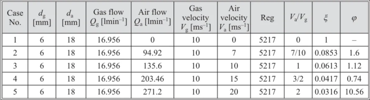
In this study, we investigate the effect of air velocity variation on the turbulent diffu-sion flame. For this reason, with a constant velocity of methane flow 10 m/s, we varied the air flow velocity between 0 and 20 m/s, as shown in tab. 1. The mixture fraction and equivalence ra-tio, two important parameters in a problem of non-premixed combustion, are given in (tab. 1). Our aim is to have the influence of air flow on the temperature distribution, on gas consumption and pollutant emissions.
Table 1. Geometrical and physical properties of the problem
Case No.
dg [mm]
da [mm]
Gas flow
Qg[lmin–1]
Air flow
Qa[lmin–1]
Gas velocity
Vg[ms–1] Air velocity
Va[ms–1]
Reg Va/Vg x j
1 6 18 16.956 0 10 0 5217 0 1 –
2 6 18 16.956 94.92 10 7 5217 7/10 0.0853 1.6
3 6 18 16.956 135.6 10 10 5217 1 0.0613 1.12
4 6 18 16.956 203.46 10 15 5217 3/2 0.0417 0.74
5 6 18 16.956 271.2 10 20 5217 2 0.0316 10.56
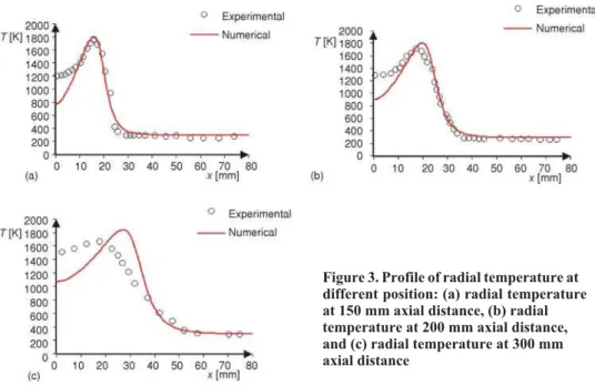
Model validation
In order to validate the CFD results, the predicted radial temperature gradients are compared to flame temperature measurements reported by [24]. Figure 3(a-c) shows the radial temperature distribution from experimental measurement and numerical prediction at different position from the burner. The radial temperature gradients, in the present flame, represent the width of the reaction zone of the flame. The predicted radial temperature profile shows satisfac-tory with the experimental measurements in terms of both trend and values. The numerical
ulation shows the predicted radial gradients of temperature imply a same reaction zone that cor-responds to the experimental measurements. The temperature values on the burner axis given by the numerical simulation are less than the values corresponding to the experimental measure-ment. For example, as shown in fig. 3(b), the predicted and measured locations of maximum temperature are 20.87 and 19.37 mm, while the predicted and measured values of maximum temperature are 1789.83 and 1670.73 K. This difference is a consequence of heat transfer be-tween the flame and the surrounding environment.
Temperature distribution
For a fixed methane flow rate and increasing values of air flow, the flame temperature distribution, the consumption of methane, the distribution of oxygen and emission NOxare de-termined numericaly. Figure 4(a-e) represents the spatial temperature distribution as a function of the variation of velocity ratio. We note, for a low air flow, the flame temperature is low and extended into a large area in a computational domain. But, the flame becomes thinner and higher when we increase the air flow. For example, in the absence of airflow (velocity ratioVa/Vg= 0), first the maximum temperature does not exceed 1590 °C, secondly, the flame starts the burner exit (no lifted flame), fig. 4(a). The maximum flame temperature varied from 1779 °C forVa/Vg
= = 7/10 to 1906 °C forVa/Vg= 2. The flame lifts fronts on the injector nozzle of the burner with increasing air jet velocity, as shown in figs. 4(b-e).
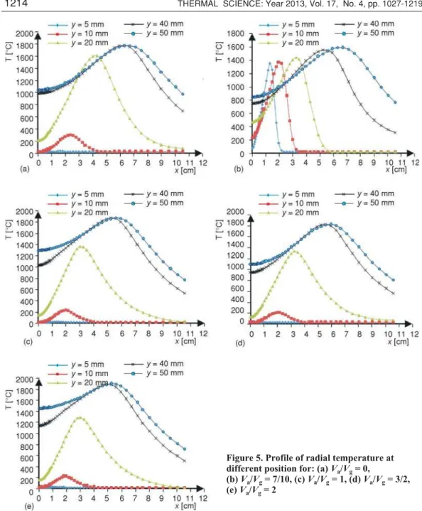
The radial variation of temperature at different heights and for different velocity ratio is shown in fig. 5. For a low velocity ratio (Va/Vg= 0), fig. 5(a), the flame starts from the burner nozzle and the temperature of the flame front is low, because the combustion reaction occurs in the absence of air. Flame temperature maximum is important when increasing velocity ratio, but appear far from the burner nozzle at a height to be near 20 cm as shown in fig. 5(b-e). The tem-perature is maximum at the flame front where the fuel and air are well premixed. The maximum temperatures represent the stoichiometric line, fig. 6. Figure 6 shows the distribution of
mum temperature in the computational domain so it shows the width of flame. The increase of velocity ratio leads to a decrease in the flame width and favors the temperature of flame front, therefore favors an increase in NOxemission.
If the velocity ratio increases, the temperature on the burner axis increases. For exam-ple, at a height of 50 cm from the nozzle burner and for a low velocity ratio, the temperature is 846 °C, the maximum temperature is 1043 °C, 1097 °C, 1296 °C, and 1457 °C corresponding, respectively, to 7/10, 1, 3/2, and 2 velocity ratio.
Mole fraction of CH4and O2
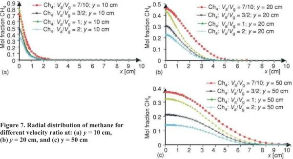
Effect of velocity ratio on the consumption of methane
Figure 7(a-c) represent the radial variation of methane at different positions of the flame and for different velocity ratio. We selected three positions downstream the burner (10 cm, 20 cm, and 50 cm) and four velocity ratios and show their effect on the CH4consumption along the flame. Figure 7(a) shows the radial variation of CH4mole fraction near the nozzle of the burner (y= 10 cm) for different velocity ratio, the mole fraction of methane presents a maximum on the burner axis and decreases when the radial positionxincreases and extends towards zero in Figure 4. Temperature
distribu-tion for different velocity ratio: (a)Va/Vg= 0, (b)Va/Vg= 7/10, (c)Va/Vg= 1, (d)Va/Vg = 3/2 and (e)Va/Vg= 1
the ambient zone. First, the maximum mole fraction decreases when the velocity ratio increases, This indicating that the amount of oxygen entrained into the jet fuel, increases with increasing air velocity. Secondly, the flame is thin when the velocity ratio increases. For example, for a low-ve-locity ratio (Va/Vg= 7/10), in a position near the burner nozzle (y= 10 cm), the mole fraction of gas equal to 0.70 on the burner axis and extend to zero at 2.1 cm radial distance. In a same posi-tion and for high velocity ratio (Va/Vg= 2) the CH4mole fraction equals to 0.344 and the amount of methane is consumed at a 1.63 cm in the radial axis. Two figures, fig. 7(b) and 7(c). show the
Figure 5. Profile of radial temperature at different position for: (a)Va/Vg= 0,
variation of CH4mole fraction for differ-ent velocity ratio at the positionyequals to 20 cm and 50 cm along the axis of the burner. The amount of methane, con-sumed by the combustion reaction, de-pends upon the height along the burner axis and the velocity ratio, so its de-creases with the heightyas the velocity ratio increases. At a height of 50 cm along the burner axis, fig. 7(c), the maxi-mum mole fraction equals to 0.37 for a velocity ratio (Va/Vg = 7/10) and equals to 0.133 for a velocity ratio (Va/Vg= 2). This means that at the distance of 50 cm
downstream the burner, the gas is consumed completely by the combustion reaction. For a fixed velocity ratio, for example (Va/Vg= 3/2) CH4mole fraction varies from 0.48 at position of 10 cm to 0.21 aty= 50 cm.
Distribution of oxygen in the reaction zone
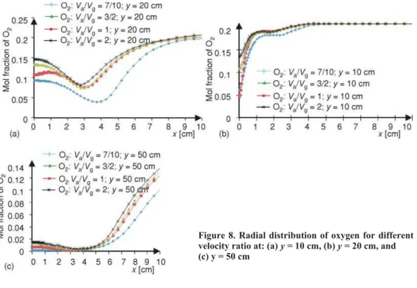
Figure 8 represents the radial variation of the mole fraction of oxygen at 10 cm, fig. 8(a), 20 cm, fig. 8(b), and 50 cm, fig. 8(c) downstream the burner nozzle (the oxidizer air is com-posed of 21% oxygen and 79% nitrogen). The distribution of oxygen in the flame indicates the quality of mixture between the fuel and air. In the non-reactive zone and near the burner, fig. 8(a), the variation of mole fraction of oxygen represents a minimum on the axis burner and in-creases rapidly to the maximum 0.21. In an intermediate section, fig. 8(b), the curves of varia-tion of mole fracvaria-tion of oxygen represent a minimum in the flame front, where the mixing be-tween methane and air is near the stoichiometry. Near the stoichiometric conditions, the quantity of gas and oxygen injected into the reaction is completely consumed by combustion re-Figure 6. Line of maximum temperature at different velocity ratio
action. The radial position of the minimum decreases when the velocity ratio increases, for ex-ample, for a ratio (Va/Vg= 7/10) the minimum mole fraction of oxygen located at a radial posi-tion of 4 cm, against for ratio (V/Vg= 2) this minimum is located at 2.8 cm radially. So the flame becomes thinner when the air velocity increases. In the upper part of the flame corresponding
y= 50 cm, fig. 8(c), the mole fraction of oxygen varies between 0 and 0.05 in the flame zone, in-dicating that the amount of oxygen injected by the burner is completely consumed by combus-tion reaccombus-tion.
NOxemission
The presence of nitrogen in the combustion reaction at a high temperature promotes the NOxproduction. This nitrogen is found with a low amount in the fuel and a large quantity in the air. The NO is formed mainly by the Thermal route, Prompt NO, Fuel NO and N2O interme-diate.
The formation of thermal NO is determined by direct oxidation of nitrogen in the oxi-dizer and was described by Zeldovich [25]. It is depends on the following reactions:
N2+ O « NO + N (R1)
N + O2 « NO + O (R2)
The overall reaction is given by:
N2+ O2 « 2NO (R3)
These reactions are slow and require high temperatures. Another reaction that may be added to the mechanism of thermal NO formation is defined by (R4):
N + OH « NO + H (R4)
The Prompt NO mechanism is responsible for NO formation in the flame front. This mechanism is through by the rapid reaction of hydrocarbon radicals with molecular nitrogen:
CH + N2 « HCN + N (R5)
The Fuel NO mechanism is responsible for the formation of NOxfrom the nitrogen content in the fuel. This mechanism depends mainly on the nitrogen content of the fuel. For cer-tain fuels this mechanism is responsible for much of the formation of NOx.
Generally N2O emission in the flame is low and the mechanism of their formation is given by Faivre [20] by the reactions:
NCO + NO « N2O + CO (R6)
NH + NO « N2O + H (R7)
More N2O reacts with H atoms by the reaction:
N2O + H « N2+ OH (R8)
The amount of NO emission is conventionally quantified by the emission index EINOx, which is generally defined as the mass of pollutat emitted per unit mass of fuel con-sumed, and can be obtained using the equation [15]:
EI
M V
M V
x
x x
V
V NO
NO NO
CH CH
d
d
4 =
ò
ò w
w 4
103 (11)
Figure 9 represents the variation of the index emission NOxas a function of velocity ratio (depends air flow) for a coaxial burner. The four curve of fig. 9 shows, respectively, the formation of thermal NO, prompt NO, N2O intermediate, and total NOx. The N2O intermediate, emission in this case is negligible compared to the other two routes. NO prompt is the basic mechanism of NOxformation in our case, by cons, when using pure oxygen as an oxidizer, the NO thermal becomes the basic mechanism of NO formation since the flame front temperature is very high. If the velocity ratio increases of (Va/Vg= 7/10) to (Va/Vg= 3/2), the NO prompt forma-tion decreases and the NO thermal emission increases, but the totalEI
x
NO formation decreases. The increase inEI
x
NO in the condition (Va/Vg= 7/10 andVa/Vg= 1) can be attributed to the in-crease in flame temperature due to the enhanced gas-air mixing leading to higher a NOxlevel. The excess of oxygen and nitrogen in the flame
(Va/Vg= 2) causes a decrease in the NO thermal formation since the temperature of the flame front starts to decrease, and increased NO prompt formation as the important amount of nitrogen in the flame.
Conclusions
The turbulent normal diffusion flame (NDF) stabilized on a coaxial burner is investi-gated in the present study for different veloci-ties ratio. The temperature distribution,
meth-Figure 9. Emission index EINOxat different
ane and oxygen profiles in the flame and NOx emission index are compared for different velocities ratio. The following results were obtained.
· With a gas flow rate constant (16.956 l/min), the variation of air flow in a coaxial burner configuration, causes a change in the flame structure and temperature distribution. The increasing of velocity ratio, due to increased air flow, causes an increase on the flame temperature, lift-off flame, and lends to a thinner flame.
· The increase on the air velocity promotes the combustion reaction due to the enhanced gas-air mixing. If the air velocity increases, the methane is rapidly consumed by the combustion reaction, almost totally methane is consumed for a velocity ratio equal to 2 at a height of 50 cm.
· If the oxidant is air, the flame characterized by a lower temperatures and high NOxemission, compared to the use of pure oxygen. So for ensure the combustion reaction in a stoichiometric conditions, it requires very large air flow, which favors the lift flame. The amount of oxygen is low on the flame front due to the enhanced gas-air mixing. At a fixed axial position; this amount is increased when the velocity ratio increases.
· The increase in the NO formation by the prompt mechanism, as the main contributor, demonstrated the observed increase in the NOxemission index. The NOxformation depends on the type of oxidizer (pure oxygen or air), the type of fuel (contains nitrogen or no), the velocity ratio and depends upon the flame temperature.
References
[1] Mahesh, S., Mishra, D. P., Flame Stability and Emission Characteristics of Turbulent LPG IDF in a
Backstep Burner,Fuel, 87(2008), 12, pp. 2614-2619
[2] Mahesh, S., Mishra, D. P., Flame Structure of LPG-air Inverse Diffusion Flame in a Backstep Burner,
Fuel, 89(2010), 8, pp. 2145-2148
[3] Sze, L. K.,et al., Appearance Temperature and NOxEmission of Two Inverse Diffusion Flames with
Dif-ferent Port Design,Combustion and Flame, 144(2006), 1-2, pp. 237-248
Nomenclature
Di – diffusion coefficient of speciesi
da – diameter of air jet, [mm]
dg – diameter of gas jet, [mm]
g – acceleration of gravity, [ms–2]
hi – enthalpy of speciesi, [J]
Ji – diffusive flux [molm–2s–1]
Jq – heat flow caused by the diffusive flux,
– [Jm–2s–1]
k – turbulent kinetic energy, [m2s–2]
Mw – molecular weight, [kgmol–1]
P – absolute pressure, [Pa]
Qa – air flow, [lmin–1]
Qg – gas flow, [lmin–1]
qr – heat radiation, [J]
R – universal gas constant, [JKg–1mol–1K–1]
Reg – Reynolds number for methane
– (=rVgdg/m)
Tr – temperature, [K]
V – overall velocity vector, [ms–1]
Va – air velocity, [ms
–1 ]
Vg – gas velocity, [ms
–1 ]
x – radial co-ordinates, [mm]
y – axial co-ordinates, [mm]
Yi – mass fraction of speciesi
Greek symbols
e – dissipation rate of kinetic energy, [m2s–3]
l – thermal conductivity, [Wm–1K–1]
m – dynamic viscosity, [kgm–1s–1]
¢
ni – stoichiometric coefficient for reactanti
– productj
¢¢
nj – stoichiometric coefficient for productj
x – mixture fraction
r – density, [kgm–3]
s – Stefan-Boltzmann constant
– (= 5.6704·10–8) [Wm–2K–4]
t – stress tensor
j – equivalence ratio
wi – production rate of speciesi, [molm
[4] Sobiesiak, A., Wenzell, J., C., Characteristics and Structure of Inverse Flames of Natural Gas, 30th
Sympo-sium International on Combustion, Chicago, Ill., USA, 2004,Proceedings,The Combustion Institute,
Pittsburgh, Penn., USA, 2005, pp. 743-749
[5] Fernández-Tarrazo, E.,et al., Liftoff and Blowoff of a Diffusion Flame between Parallel Streams of Fuel
and Air,Combustion and Flame, 144(2006), 1-2, pp. 261-276
[6] Santos, A., Costa, M., Reexamination of the Scaling Laws for NOxEmissions from Hydrocarbon
Turbu-lent Jet Diffusion Flames,Combustion and Flame, 142(2005), 1-2, pp. 160 -169
[7] Meunier, Ph.,et al., On NOxEmissions from Turbulent Propane Diffusion Flames,Combustion and
Flame, 112(1998), 1-2, pp. 221-230
[8] Montgomery, C. J.,et al., The Effect of Coflow Velocity on a Lifted Methane-Air Jet Diffusion Flame,
27thSymposium International on Combustion, Boulder, Cal., USA, 1998,Proceedings, The Combustion
Institute, Pittsburgh, Penn., USA, 1999, pp. 1175-1182
[9] Oh, J.,et al., Nitrogen Dilution Effect on Flame Stability in a Lifted Non-Premixed Turbulent Hydrogen Jet with Coaxial Air,Fuel, 89(2010), 7, pp. 1492-1498
[10] Mishra, D. P., Kumar, P., Experimental Investigation of Lamianr LPG-H2 Jet Diffusion Flame with Pre-heated Reactants,Fuel, 87(2008), 13-14, pp. 3091-3095
[11] Mishra , D. P., Kumar, P., Experimental Study of Bluff-Body Stabilized LPG-H2 Jet Diffusion Flame with Preheated Reactant,Fuel, 89(2010), 1, pp. 212-218
[12] El-Ghafour, S. A. A.,et al., Combustion Characteristics of Natural Gas-Hydrogen Hybrid Fuel Turbulent Diffusion Flame,International Journal of Hydrogen Energy, 35(2010), 6, pp. 2556-2565
[13] Oh, J.,et al., Acoustic Excitation Effect on NOxReduction and Flame Stability in a Lifted Non-Premixed
Turbulent Hydrogen Jet with Coaxial Air,International Journal of Hydrogen Energy, 34(2009), 18, pp. 7851-7861
[14] Wyzgolik, A., Stabilization of Non-Premixed Flame in a Coaxial Jet, Effect of Acoustic Field (in French), Ph. D. thesis, Faculty of the University of Rouen, France, 2008
[15] Lee, K. W., Choi, D. H., Analysis of NO Formation in High Temperature Diluted Air Combustion in a Co-axial Jet Flame Using an Unsteady Flamelet Model,International Journal of Heat and Mass Transfer, 52
(2009), 5-6, pp. 1412-1420
[16] Masson, E., Experimental Study of Dynamic and Scalar Fields of Flameless Combustion (in French), Ph. D. thesis, National Institute of Applied Sciences of Rouen, France, 2005
[17] Choi, G. M., Katsuki, M., Advanced Low NOxCombustion using Highly Preheated Air,Energy
Conver-sion and Management, 42(2001), 5, pp. 639-652
[18] Boushaki, T.,et al., Effects of Inclined Jets on Turbulent Oxy-Flame Characteristics in a Triple Jet Burner,
Experimental Thermal and Fluid Science, 32(2008), 7, pp. 1363-1370
[19] Lederlin, Th., Conception and Experimental and Numerical Study of a Control System of Trajectory and Mixture Gas Jets in the Oxygen Burners (in French), Ph. D. thesis, Institute National Polytechnique, Toulouse, France, 2007
[20] Faivre, V., Experimental and Numerical Study of the Active Control of Jets in Combustion Chambers (in French), Ph. D. thesis, Institut National Polytechnique, Toulouse, France, 2003
[21] Delmaere, Th., Study of the Effect of a Magnetic Field Gradient on theDevelopment of Laminar Diffusion Flames (in French), Ph. D. thesis, Graduate School Science and Technology ICARE CNRS Orleans, France, 2008
[22] Launder, B. E., Spalding, D. B., The Numerical Computation of Turbulent Flows,Computer Methods in
Mechanics and Engineering, 3(1974), 2, pp. 269-289
[23] Chen, L., Zheng, S., Yong, Oxy-Fuel Combustion of Pulverized Coal: Characterization, Fundamentals, Stabilization and CFD Modeling,Progress in Energy and Combustion Science, 38(2012), 2, pp. 156-214 [24] Brookes, S. J., Moss, J. B., Measurements of Soot and Thermal Radiation from Confined Turbulent Jet
Diffusion Flames of Methane,Combustion and Flame, 116(1999), 1-2, pp. 49-61
[25] Salentey, L., Experimental Study of the Behavior of Burners with Separated Jets Application to Combus-tion of Natural Gas/Oxygen pure (in French), Ph. D. thesis, Faculty of Science and Technology of the Uni-versity of Rouen, France, 2002