Goertzel Algorithm Based Shunt Active Power
Filter Using Sliding Mode Controller
Sushil Karvekar, Swapnil Patil, A.M.Mulla, Dadgonda Patil,Member, IAENG
Abstract—In this paper control of Goertzel Algorithm based shunt active power filter with sliding mode controller is considered. Shunt active power filter involves harmonics mitigation due to three phase non linear loads under balanced and unbalanced load conditions. The sliding mode controller is used to regulate voltage of the capacitor used in inverter. The sliding mode controller improves the dynamic response of the system and provides faster convergence. The performance of the sliding mode controller is compared with the conventional PI controller. The above system is investigated for balanced and unbalanced load conditions using MATLAB/Simulink. From the analysis it can be observed that the Goertzel algorithm based shunt active power filter with sliding mode controller gives a better response than the conventional PI controller. The simulation results prove the effectiveness of the proposed system.
Keywords—Shunt active power filter, total harmonic distortion,Goertzel Algorithm, sliding mode controller.
I. INTRODUCTION
The increased use of nonlinear loads, such as switch mode power supply in computers, rectifier devices in TVs, ovens and telecommunication power supplies and commercial lighting systems cause excessive neutral currents, harmonic injection and reactive power burden in the power system. They result in poor power factor, lower efficiency and interference to adjacent communication systems. In the past L-C filters were employed to reduce harmonics and power capacitors were used to improve the power factor of the AC mains, however, they have the demerits of fixed compensation level, large size and resonance. In the last two decades, a device generally named as active power filter (APF) has been investigated to provide an appropriate solution to most of these problems. Elimination of current harmonics, reactive power compensation and voltage regulation are the main functions of active power filters for the improvement of power quality. T. C. Author is with the Electrical Engineering Department, University of Colorado, Boulder, CO 80309 USA, on leave from the National Research Institute for Metals, Tsukuba, Japan (e-mail: [email protected]).
There exist several active power filter topologies in the literature in accordance with their circuit configurations and connection types [1]. There are different control methods that are introduced by different authors. In [2] simplified method using instantaneous power theory based shunt
Manuscript received March 24, 2014; revised April 15, 2014. This work was supported in part by the Department of electrical engineering of Walchand College of Engg, Sangli and Annasaheb Dange College of Engg and Tech, Ashta, India.
Sushil Karvekar and Dadgonda Patilare with the Dept. of Electrical Engineering, Walchand College of Engineering Sangli, India. (e-mail- [email protected] and [email protected]).
Swapnil Patil and A.M.Mulla are with the Dept. of Electrical Engineering, Annasaheb Dange College of Engineering and Technology, Ashta, India. ([email protected] and [email protected])
active power filter using PI controller is discussed. They have used hysteresis current control technique for pulse generation. In [3] active power filter with sliding mode control is discussed which is capable of controlling dc bus voltage of capacitor as well. The ANN based shunt active power filter is discussed in [4].
Shunt active power filter (SAPF) is made up of inverter and a control circuitry, which decides operation of inverter. SAPF provides harmonic compensation as well as reactive power compensation. In this paper we discuss only about harmonics compensation using hysteresis control technique. The PI controller is used to control the voltage across the capacitor. This paper uses Synchronous Reference Frame method for reference current calculation.[5-8]
Shunt Active Power Filters are mainly operated as harmonic isolator between nonlinear load and utility system. The SAPF connected in parallel to supply system protects utility from harmonics generated by non-linear load. It can be used to provide reactive power to the load as well. Fig. 1 shows basic schematic of Shunt Active Power Filter constituting of following steps:[9-11]
• Measurement of Current and Voltage signals • Reference Current generation
• Pulses generation for operation Inverter
The use of Goertzel algorithm constitutes an alternative method for DFT which reduces the number of operations. Goertzel algorithm evaluates the DFT and saves computation time as well as storage memory, as there are only two real coefficients to store if compared with the 2N coefficients required by DFT. Regarding to the number of operations, Goertzel algorithm employs only N + 1 multiplications and 2N + 2sums
II. SLIDING MODE CONTROLLER
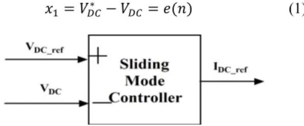
Better operation of Shunt APF is guaranteed if the voltage across DC link capacitor is maintained at prescribed reference DC voltage. Sliding Mode Controller is used to regulate voltage across capacitor by comparing it with reference DC voltage. The controller sets a reference DC current required to maintain the voltage across capacitor constant. This is done as shown in figure 1 below.
The error is calculated as difference between reference and measured DC voltage.[10-11]
∗ (1)
The derivative of error,
(2) Where, T is sampling interval and , are state variables. The state equation is given by equation (3) below.
(3)
The sliding mode plane is represented by equation (4) below.
(4)
And is given by,
(5)
In this paper Constant Rate Reaching Law is used which is given as,
∗ (6) Where,
(7)
Putting equation (3) in (5) and after that equating it with equation (6), we can get the required control law , as shown below.
∗ (8)
The output of sliding mode controller is taken as _ , which is then multiplied by to generate capacitor power loss component .
If we directly implement this law for Shunt APF system, the voltage across capacitor never approaches the reference DC voltage. There exists steady state error of magnitude nearly equal to 3 volts as shown in figure 9.
This steady-state error can be eliminated by placing a constraint on control law specified in equation (8). The constraint placed is stated in equation (9) below.
∗ ∗ | | (9)
Where, η :- Positive Constant.
The value of η determines the degree to which the system state is attracted to the switching surface.
Equation (9) states that, the squared distance to the sliding surface ( ) decreases along all system trajectories. Thus it constraints the trajectories to point towards the surface “ ”.
A. Augmenting the equivalent control:
Here, the VSC control takes the form,
∆
Where, , is the equivalent sliding mode control, whereas
∆ is added to satisfy the reaching condition. A commonly used form for Au is a relay control.
B. Relay control:
Here, the VSC for each element of the control vector ∆ takes the form of a relay. The relay gain may be either fixed or state dependent.
∆ ,
∆ ,
Where, , , … .
The values of and are chosen to satisfy the desired reaching condition.
The output of sliding mode control is taken as _ , which is required to charge the capacitor.
C. Chattering Problem Elimination:
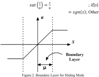
Due to use of signum function for designing SMC law introduces chattering effect which is undesirable in any dynamic system due to its infinite switching frequency. Chattering problem can be overcome by smoothing out the signal with continuous function like Saturation, which closely approximate the signum function especially around the neighborhood of the sliding surface. The saturation function allows the introduction of a small boundary layer near the surface. So we can substitute sgn(s) by sat (s/µ) as follows:
; if| | μ
; Otherwise
Figure.2. Boundary Layer for Sliding Mode
Fig. 4 shows boundary layer control by using saturation function, where “u” is magnitude of control action.
III. CONTROL STRATEGY BASED ON GOERTZEL
ALGORITHM
The Goertzel algorithm is used to compute Discrete Fourier Transform spectra. It is a special case of DFT where the algorithm provides amplitude spectra and phase spectra only for a specified number of frequencies. The algorithm is implemented in the form of second order infinite impulse response filter. The block diagram for Goertzel algorithm is as shown in Figure 2. The values of coefficients are as
follows: cos and .
The amplitude and phase of 50 Hz component can be obtained using above algorithm as
| |
cos
(1)
arg
sin cos
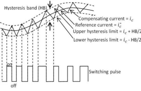
(2) This paper introduces use of Goertzel algorithm for the extraction of fundamental component of current and voltage and its use in Shunt Active Power filter. The method can detect the amplitude and phase accurately under noisy environment. Thus the reference current generation for the shunt active power filter is done using this method. The advantages of the method are that the accuracy and speed of response can be controlled, the structure is robust with respect to setting of internal parameters and the performance is immune to noise and external distortions. Hysteresis Current Controller is an instantaneous feedback system which detects the current error and produces directly the drive commands for the switches when the error exceeds an assigned band. The hysteresis controller is used to control the current and determine the switching signals
for inverter gates. When ∗ / then
hysteresis controller gives output 0. When ∗
/ then it gives output equal to one. In this way, Hysteresis PWM is used as pulse generator for inverter, so that current tracks the reference.[12-13]
Figure 4. Hysteresis Current Controller
DC voltage controller is used to regulate dc voltage across the capacitor .The regulation loop consists of the comparison of the measured voltage with the reference voltage and the error is given to PI controller which sets ∗ reference current as shown in figure 4. This reference current is added to output of the Low Pass Filter.
Figure 5. DC voltage controller
IV. P W
The basic aim of this paper is to simulate the implementation of SAPF for power quality improvement using Goertzel algorithm with DC voltage control using PI controller and Sliding Mode Controller and performance comparison. To simulate the two methods under discussion, MATLAB/ Simulink is used with diode bridge rectifier as the linear load. This load makes the load current non-sinusoidal and to keep the source current as clean as possible, Shunt Active Power Filter (SAPF) is used. For the reference current generation for this SAPF, the above mentioned two methods are separately implemented and compared for performance specifications like source current THD and amplitude, voltage balancing, source power factor, dynamic response and response speed.
In the simulation diagram as shown in figure 6,the load current is sensed using Goertzel algorithm. The algorithm extracts the 50 Hz component of the load current. Thus, the fundamental components of three phase load currents are measured. The output of algorithm consists of magnitude and phase of the fundamental component of current. The power supplied to the inverter used in SAPF through the DC link capacitor and the current required to charge this capacitor is taken from the source itself. This current is termed as loss current which is then added to the fundamental current computed by Goertzel algorithm to find the total current to be compensated. The three phase template currents are generated with their amplitudes equal to the addition of fundamental current and the loss current. These template currents are subtracted from the load current and the resultant is then compared with the compensating current using Hysteresis current controller.
Thus the reference current signals are generated for the switching of PWM inverter.
To study the performance of Goertzel algorithm under balanced load conditions, THD of load current is 23.09%
with the magnitude of fundamental current being
18.75ampere for both, PI controller and SMC whereas THD of source current is 2.55%with the magnitude of fundamental current being 18.04amperefor PI controller as against THD of source current is 1.55%with the magnitude of fundamental current being 18.04amperefor SMC. The waveforms of load and source currents for balanced load condition are shown in Fig.7 and 8 respectively. Figures 9 and 10 respectively show Voltage balancing of DC link capacitor of SAPF using PI Controller and using SMC under balanced load conditions.
Figure 6. Goertzel algorithm for reference current generation under unbalanced load conditions with DC voltage balancing using PI controller or SMC
Figure 7. Waveform of load current (balanced load)
Figure 8. Waveform of source current (balanced load)
Figure 9. Voltage balancing of DC link capacitor of SAPF using PI Controller (balanced load)
Figure 10. Voltage balancing of DC link capacitor of SAPF using Sliding Mode Controller (balanced load)
Figure 11. Waveform of load current with dynamic change in load (unbalanced)
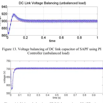
Figure 13. Voltage balancing of DC link capacitor of SAPF using PI Controller (unbalanced load)
Figure 14. Voltage balancing of DC link capacitor of SAPF using Sliding Mode Controller (unbalanced load)
THD of load current is 27.34% with the magnitude of fundamental current being 35.54ampere for both, PI controller and SMC whereas THD of source current is
2.90%with the magnitude of fundamental current being
30.43amperefor PI controller as against THD of source current is 1.45%with the magnitude of fundamental current being 30.43ampere for SMC.
Table 1 Performance Analysis of PI and SMC Controllers
V. CONCLUSION
The simulation results show the performance of Shunt Active Filter using Goertzel Algorithm and Enhanced Phase Locked Loop. The Goertzel Algorithm provides faster response as compared to EPLL based system. The system reaches steady state within 1 to 2 cycles in Goertzel Algorithm and so a faster convergence is possible with this method. The calculations required for implementing the Goertzel algorithm are less as compared to EPLL. So, the implementation of Goertzel Algorithm for reference current generation is easier as compared to EPLL. Both the methods perform good under unbalanced conditions and are insensitive to voltage perturbations.
REFERENCES
[1] H. Akagi, “Active Harmonics Filters” Proceedings of IEEE, Vol. 93, pp. 2128-2141, 2005.
[2] Wong A.Y.K., Cheng D.K.W.,Lee Y.S., "Harmonic compensation for nonlinear loads by active power," Power Electronics and Drive Systems, 1999. PEDS '99. Proceedings of the IEEE 1999 International Conference on , vol.2, pp.894-899 vol.2, 1999
power system quality”, McGraw-Hill, New York, (1996)
[4] Asiminoaei L., Blaabjerg F., Hansen S., Thogersen P., "Adaptive Compensation of Reactive Power With Shunt Active Power Filters," Industry Applications, IEEE Transactions on , vol.44, no.3, pp.867-877, May-June 2008
[5] Gupta N., Singh S.P., Dubey S.P., "Fuzzy logic controlled shunt active power filter for reactive power compensation and harmonic elimination," Computer and Communication Technology (ICCCT), 2011 2nd International Conference pp.82-87, 15-17 Sept. 2011
[6] Kalaignan T.P., Raja T.S.R., "Harmonic elimination by Shunt active filter using PI controller," Computational Intelligence and Computing Research (ICCIC), 2010 IEEE International Conference pp.1-5, 28-29 Dec. 2010
[7] E. Ozdemir, M. Ucar, M. Kesler, M. Kale, “The Design and Implementation of a Shunt Active Power Filter based on Source Current Measurement”, The IEEE International Electric Machines and Drives Conference, IEMDC 2007, Antalya, Turkey, 608-613, (2007)
[8] Tsengenes G., Georgios A., "Shunt active power filter control using fuzzy logic controllers," Industrial Electronics (ISIE), 2011 IEEE International Symposium on , vol., no., pp.365-371, 27-30 June 2011
[9] Bhattacharya A., Chakraborty C., "A Shunt Active Power Filter With Enhanced Performance Using ANN-Based Predictive and Adaptive Controllers," Industrial Electronics, IEEE Transactions on , vol.58, no.2, pp.421-428, Feb. 2011
[10] Vadim Utkin, Jürgen Guldner Jingxin Shi, “Sliding Mode Control in Electro-Mechanical Systems”, CRC Press Boca Raton, 2009 [11] Hung J.Y., Gao W., Hung J.C., "Variable structure control: a
survey," Industrial Electronics, IEEE Transactions on , vol.40, no.1, pp.2-22, Feb 1993
[12] Goertzel, G,“An algorithm for the evaluation of finite trigonometric Series”, Amer. Math. Monthly, pp. 34-35,1965 [13] S. A. González, R. García-Retegui, and M. Benedetti, “Harmonic
Computation Technique Suitable for Active Power Filters” IEEE Trans. On Indu. Electronics, Vol. 54, No. 5, October 2007
Sushil Karvekar aged has obtained his B.E. (Electronics) degree with First Class in 2010 from Shivaji University Kolhapur (MS) and M.tech Electrical (Control Systems) Degree from Walchand College of Engineering Sangli in 2013. He has one year industrial experience and is working as Assistant Professor at Walchand College of Engineering, Sangli. He has five international publications and one national publication. His areas of interest are Embedded Systems and FACTS.
Dr. D. R. Patil aged 55 has obtained his B.E. (Electrical) Degree in First Class in 1983 and M.E. (Electrical) Degree in First Class from Shivaji University, Kolhapur (MS). He also obtained the Ph.D. Degree from the same university in 2012. He started his teaching carrier from 1985, as a Lecturer in Electrical Department of Walchand College of Engineering, Sangli (MS). Subsequently in 1993 he was promoted to Assistant Professor of Control Systems on the Post Graduate. He has about 45 International Conference / Seminars publications. He was a Chairman, Board of Studies; Member of Academic Council of Shivaji University, Kolhapur during 2001-2005. His areas of interest are Control Systems and power systems.
Controller Performance Analysis Settling Time (sec) Rise Time Peak
Time % Overshoot
PI 0.2 0.02 0.03 14.38
Swapnil D. Patil aged 23 has obtained his B.E. in Electrical Engineering with First Class with distinction in 2013 from Shivaji University, Kolhapur (MS). Currently he is pursuing his post graduation from the same university. He has three international Conference publications. His areas of interest are Power System, FACTS and Power Quality.